technical data SKODA FABIA 2010 2.G / 5J Owner's Guide
[x] Cancel search | Manufacturer: SKODA, Model Year: 2010, Model line: FABIA, Model: SKODA FABIA 2010 2.G / 5JPages: 244, PDF Size: 29.53 MB
Page 42 of 244
Unlocking and locking
41
Using the system
Safety
Driving Tips
General Maintenance
Breakdown assistance
Technical Data
– Fold one of the outer rear seats forwards. – Move the operating lever with the aid of a
narrow object, e.g. a screwdriver, up to
the stop in the direction of arrow
page 40, fig. 30
and then unlock in the
direction of arrow .
– Open the boot lid from the outside.Remote control*DescriptionYou can use the remote control:
to unlock and lock the vehicle;
unlocking boot lid.
The transmitter with the battery is incorporat
ed in the handle of the master key. The
receiver is located in the interior of the car. The operating range of the remote control key is approx. 10 m. But this range can be reduced if the batteries are weak. The master key has a fold-open key bit which can be used for unlocking and locking the car manually and also for starting the engine. If a lost key is replaced or if the receiver unit has been repaired or a new unit installed, it is then necessary for a specialist garage to adapt the system. Only after this is it possible to again use the remote control.
Note
The remote control is automatically deactivated when the ignition is switched on.
The operation of the remote control may temporarily be affected by interference
from transmitters close to th
e car and which operate in the same frequency range (e.g.
mobile phone, TV transmitter).
The battery must be replaced if the centra
l locking or anti-theft alarm system does
not react to the remote control at less th
an 3 metres away. We recommend having the
battery replaced by
a specialist garage.
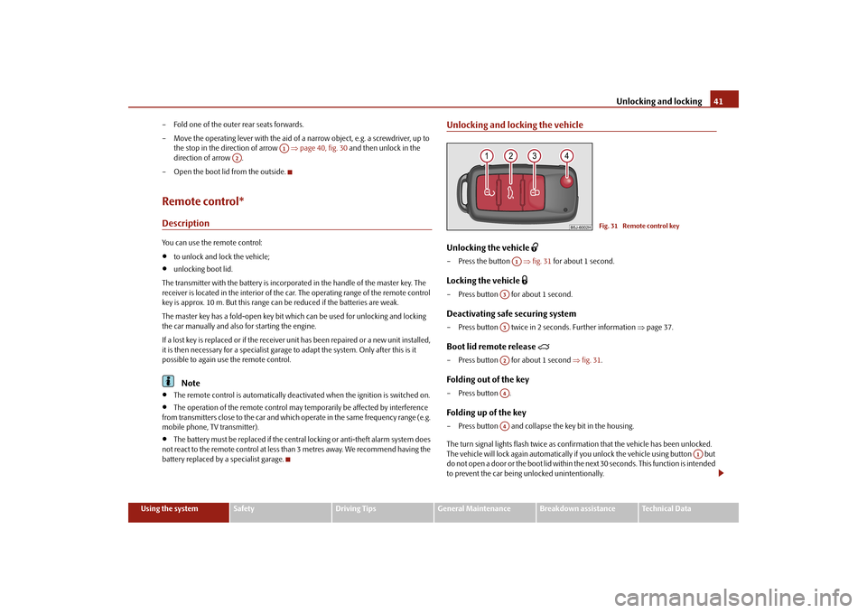
Unlocking and locking the vehicleUnlocking the vehicle
– Press the button
fig. 31
for about 1 second.
Locking the vehicle
– Press button for about 1 second.Deactivating safe securing system– Press button twice in 2 seconds. Further information
page 37.
Boot lid remote release
– Press button for about 1 second
fig. 31
.
Folding out of the key– Press button .Folding up of the key– Press button and collapse the key bit in the housing. The turn signal lights flash twice as confir
mation that the vehicl
e has been unlocked.
The vehicle will lock again automatically if
you unlock the vehicle using button but
do not open a door or the boot lid within th
e next 30 seconds. This
function is intended
to prevent the car being unlocked unintentionally.
A1
A2
Fig. 31 Remote control key
A1
A3A3A2A4A4
A1
s3j8.a.book Page 41 Tuesday, April 20, 2010 1:10 PM
Page 44 of 244
Unlocking and locking
43
Using the system
Safety
Driving Tips
General Maintenance
Breakdown assistance
Technical Data
A drop in voltage of the on-board power supply.
An alarm is immediately triggered if either of the two battery terminals is disconnected while the anti-theft alarm system is activated. How is the alarm switched off? You switch the alarm off if you unlock the vehi
cle with the radio remote control or if you
switch the ignition on.
Note
The working life of the alarm siren is 5 years. More detailed information is available
by a specialist garage.
Before leaving the car, check that all the doors, windows and the electric
sliding/tilting roof* are properly closed in order to ensure that the anti-theft alarm system is fully operational.
Coding of the radio remote control and th
e receiver unit precludes the use of the
radio remote control from other vehicles.Interior monitor* and Towi
ng protection monitoring*
The interior monitor and the towing protection monitoring detect movements inside the vehicle interior and then trigger the alarm.The interior monitor and the towing protec
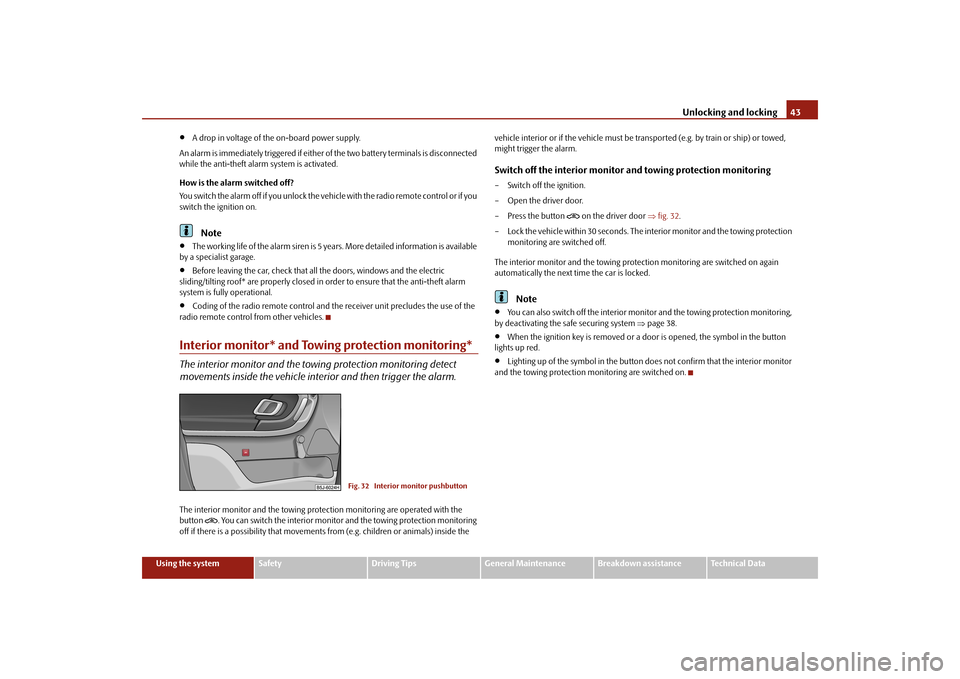
tion monitoring are operated with the
button
. You can switch the interior monitor
and the towing protection monitoring
off if there is a possibility that movements from (e.g. children or animals) inside the
vehicle interior or if the vehi
cle must be transported (e.g. by train or ship) or towed,
might trigger the alarm.Switch off the interior monitor and towing protection monitoring– Switch off the ignition. – Open the driver door.– Press the button
on the driver door
fig. 32
.
– Lock the vehicle within 30 seconds. The in
terior monitor and the towing protection
monitoring are switched off.
The interior monitor and the towing protec
tion monitoring are switched on again
automatically the next ti
me the car is locked.
Note
You can also switch off the interior moni
tor and the towing protection monitoring,
by deactivating the sa
fe securing system
page 38.
When the ignition key is removed or a door is opened, the symbol in the button
lights up red.
Lighting up of the symbol in the button
does not confirm that the interior monitor
and the towing protection mo
nitoring are switched on.
Fig. 32 Interior monitor pushbutton
s3j8.a.book Page 43 Tuesday, April 20, 2010 1:10 PM
Page 46 of 244
Unlocking and locking
45
Using the system
Safety
Driving Tips
General Maintenance
Breakdown assistance
Technical Data
After switching the ignition off, it is still possible to open or close the windows for a
further 10 minutes. The power windows are
switched off completely once you open
the driver or front passenger door.
When driving always use the existing he
ating, air conditioning and ventilation
system for ventilating the interior of the vehicle. If the windows are opened, dust as well as other dirt can get into the vehicle
and in addition the wind noise is more at
certain speeds.Force limiter of the power windowsThe electrically operated power windows are fitted with a force limiter. It reduces the risk of bruises or injuries when closing the windows. If there is an obstacle, the closing process is stopped and the window goes down by several centimeters. If the obstacle prevents the window from being closed during the next 10 seconds, the closing process is interrupted once agai
n and the window goes down by several
centimeters. You must try to close the window once agai
n within 10 seconds after the window has
gone down twice, even if the obstacle was not yet removed, the closing process is stopped. During this time it is not poss
ible to automatically
close the window. The
force limiter is still switched on. The force limiter is only switched off, if yo
u attempt to close the window within the next
10 seconds -
the window closes now with full strength!
If you wait longer than 10 seconds, the force limiter is switched on again.
WARNING
You should take particular care when closing the windows! You may otherwise suffer severe injuries as a result of getting an arm, for example, jammed in the window!Window convenience operationYou can open and close the electrically po
wered windows as follows when unlocking
and locking the vehicle (only close the sliding/tilting roof):
Opening a window– Hold the key in the locking cylinder of the
driver's door in the
unlock position or
press the unlock button of the radio re
mote control until all the windows are
opened.
Closing a window– Hold the key in the locking cylinder of the driver's door in the lock position or press
the lock button of the radio remote co
ntrol until all the windows are closed.
You can interrupt the opening or closing
operation of the windows immediately by
releasing the key or the lock button.
WARNING
The system is fitted with a force limiter
page 45. If there is an obstacle, the
closing process is stopped and the window goes down by several centimeters. You should then take particular care when closing the windows! You may otherwise suffer severe injuries as a re
sult of getting an arm, for example,
jammed in the window!Operational faultsElectrically operated powe
r windows do not operate
If the battery of the car has been disconnect
ed and then reconnected, the electrically
operated power windows do not operate. Th
e system must be activated. Proceed as
follows in order to re-establish the function:
Switch on the ignition,
slightly pull on the upper edge of the rele
vant button and hold it until the window
is closed,
release the switch,
you must pull the respective switch again in upward direction for approx. 3
seconds.
s3j8.a.book Page 45 Tuesday, April 20, 2010 1:10 PM
Page 48 of 244
Unlocking and locking
47
Using the system
Safety
Driving Tips
General Maintenance
Breakdown assistance
Technical Data
ClosingSliding closed/closing the sliding/tilting roof– Turn the switch to position
page 46, fig. 34
.
Safety closing The sliding/tilting roof is fitted with a force limiter. The sliding/tilting roof stops and moves back several centimetres when it ca
nnot be closed because there is something
in the way (e.g. ice). You can close the sliding/tilting roof completely without force limiter by pressing the sw
itch to the position
page 46, fig. 34
at the front for as
long as it takes for the sliding/
tilting roof to close completely
.
WARNING
Close the sliding/tilting roof carefully - risk of injury!Convenience operationYou can also close an open sliding/tilting roof from the outside. – Hold the key in the locking cylinder of the dr
iver's door in the lo
ck position or press
the lock button of the remote control unt
il the sliding/tilting roof is closed.
The closing operation stops when one re
leases the key or the lock button.
Note
The force limiter also operates for convenience closing.
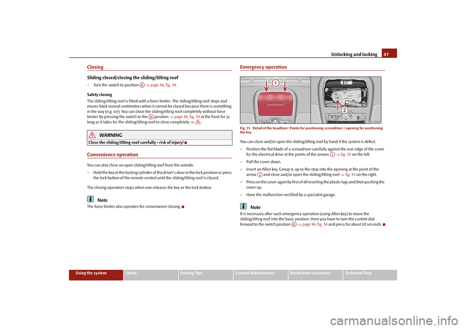
Emergency operationFig. 35 Detail of the headliner: Points for
positioning screwdriver / opening for positioning
the keyYou can close and/or open the sliding/tiltin
g roof by hand if the system is defect.
– Position the flat blade of a screwdriver carefully against the rear edge of the cover
for the electrical drive at the points of the arrows
fig. 35
on the left.
–Pull the cover down.– Insert an Allen key, Group 4, up to the stop into the opening at the point of the
arrow and close and/or open
the sliding/tilting roof
fig. 35
on the right.
– Press on the cover again by first of all in
serting the plastic lugs and then pushing the
cover up.
– Have the malfunction rectified by a specialist garage.
Note
It is necessary after each emergency op
eration (using Allen key) to move the
sliding/tilting roof into the basic position
. Here you have to tu
rn the control dial
forward to the switch position
page 46, fig. 34
and press for about 10 seconds.
AA
AA
A1
A2
AA
s3j8.a.book Page 47 Tuesday, April 20, 2010 1:10 PM
Page 50 of 244
Lights and Visibility
49
Using the system
Safety
Driving Tips
General Maintenance
Breakdown assistance
Technical Data
– Turn the light switch into position O
page 48, fig. 36
- left.
– Switch on the switch for daylight driving lights
page 48, fig. 36
- right.
Activating daylight driving lights*
on vehicles with the “START-STOP”
system– Pull the turn signal light lever towards the
steering wheel, at the same time slide it
to the top and hold it in this position.
– Switch on the ignition - the right turn signal light flashes 4x.– Switch off the ignition - an audible signal
sounds, which confirms
the activation of
the daylight driving lights.
– Release the turn signal light lever.Deactivating daylight driving lights*– Switch off the switch for daylight driving lights
page 48, fig. 36
- right.
– Turn the light switch to the position side lights
or low beam
page 48,
fig. 36
- left.
Deactivating daylight driving ligh
ts* on vehicles with the “START-
STOP” system– Pull the turn signal light lever towards the
steering wheel, at the same time slide it
to the bottom and hold it in this position.
– Switch on the ignition - the left turn signal light flashes 4x.– Switch off the ignition - an audible signal
sounds, which confir
ms the deactivation
of the daylight driving lights.
– Release the turn signal light lever. On vehicles with separate ligh
ts* for daylight driving lights in the fog lights or in the
front bumper, the parking lights and the lice
nce plate light do not come on when acti-
vating the function daylight drivin
g lights (neither front nor rear).
If the vehicle is not equipped with separate lights* for daylight driving lights, the combination of the low beam, the parking ligh
ts (front and rear) including the licence
plate light is used as daylight driving lights.
In some countries, the national
legal provisions require that the rear parking lights also
come on together with the separate lights* for daylight driving lights when activating the function daylight driving lights.Halogen projector headlights with cornering light function*For a better cornering illumination, the halogen projector headlights with cornering light function are set in the optimal position in line with the vehicle speed and the steering angle. If the warning light
comes on while driving or after the ignition is switched on, a
fault is confirmed.
WARNING
If there is a fault in the halogen projec
tor headlights with
cornering light func-
tion, the warning light
lights up in the instrument cluster. The halogen
projector headlights with cornering light function are automatically lowered to the emergency position, which prevents a po
ssible dazzling of oncoming traffic.
Thus the illuminated length of the road is shortened. Drive carefully and have the car inspected immediately by a specialist garage.Tourist light*Halogen projector headlights with cornering light functionThis mode makes it possible to drive in countries with opposing traffic system, driving on the left/right, without dazzling the oncoming vehicles. When the mode “tourist light” is active, the side to side swivel of the headlights is deactivated.Activating tourist lightBefore activating the tourist light,
the following condit
ions must be met:
Ignition switched off, light switched off (light switch in the position O), control dial for the headlamp beam adjustment in the position
0, no gear engaged or selector lever in
the position
N (automatic gearbox), tourist light deactivated.
– Switch on the ignition.Up to 10 seconds after the ignition is switched on:
s3j8.a.book Page 49 Tuesday, April 20, 2010 1:10 PM
Page 52 of 244
Lights and Visibility
51
Using the system
Safety
Driving Tips
General Maintenance
Breakdown assistance
Technical Data
If the vehicle is not fitted with fog lights*, the rear fog light is switched on by turning the light switch to the position
and is pulled out directly to the position . This switch
does not have two position
s, but only one position.
The warning light
lights up in the instrument cluster when the rear fog light is
switched on
page 26.
Only the rear fog light of the trailer lights up if the vehicle is fitted with a
towing device
from Škoda original accessories
and when you are towing a trailer which is fitted
with the rear fog light.
Caution
The rear fog light should only be switched on
if visibility is particularly poor (conform
with any varying legal provisions) to avoi
d dazzling vehicles be
hind your vehicle.
Headlamp range adjustment
Once the low beam is switched on
you can then adapt the range of the
headlights to the lo
ad of the vehicle.
– Turn the control dial
fig. 38
until you have adjusted the low beam so that
oncoming traffic is not dazzled.
Settings The positions correspond
approximately to the
following vehicle loads:
Front seats occupied, luggage compartment empty. All seats occupied, luggage compartment empty.
All seats occupied, luggage compartment laden. Driver seat occupied, luggage compartment laden.Caution
Set the headlight beam adjustment in su
ch a way as to avoid dazzling oncoming
traffic.Switch for hazard warning lights
– Press switch
fig. 39
to switch the hazard warning light system on or off.
All the turn signal lights on the vehicle flas
h at the same time when the hazard warning
light system is switched on. The indicator
light for the turn signals and the indicator
light in the switch also flash at the same time. You can also switch on the hazard warning light system if the ignition is switched off. The hazard warning light system is switched on automatically if an airbag is deployed in the event of an accident. Please comply with any legal requirements when using the hazard warning light system.
Note
Switch on the hazard warning light system if, for example:
you encounter traffic congestion;
your vehicle breaks down or an emergency situation occurs.
A2
Fig. 38 Dash panel:
Lights and Visibility
A-A1
A2A3
Fig. 39 Dash panel: Switch for hazard warning lights
s3j8.a.book Page 51 Tuesday, April 20, 2010 1:10 PM
Page 54 of 244
Lights and Visibility
53
Using the system
Safety
Driving Tips
General Maintenance
Breakdown assistance
Technical Data
Interior lightingLighting of the interior of the vehicle front/rear* - typ 1Door contact switching mechanism (front and rear* doors)– Press the switch to the right, the symbol
appears
fig. 41
.
Switching the interior light on– Press the switch to the left, the symbol
appears.
Switching the interior light off– Press the switch into
the middle position
O.
Reading lights
– Press on one of the switches
fig. 41
in order to switch the right or left reading
light on or off.
On vehicles with central locking, the interi
or light is switched on for about 30 seconds
when the vehicle is unlocked, when a door is
opened or after withdrawing the ignition
key (if the relevant switch is in the door co
ntact position). The inner light goes out out
immediately after the ignition is switched on. A time delay switch* causes
the inner lighting on vehicl
es without a central locking
system stays on for a few seconds after the doors have been closed. The inner light goes out out immediately after the ignition is switched on.
The interior lighting is switched off after
about 10 minutes when a door has been left
open in order to avoid discharg
ing the battery of the vehicle.
Front interior lighting - without reading lightsThe rear interior lighting
fig. 42
is actuated by moving the switch to the symbol
,
O or to the middle position
.
The same principles apply for th
e interior lighting at the rear as for the for the interior
lighting at the front
page 53.
Note
We recommend having the bulb re
placed by a specialist garage.
Rear interior lighting* - type 2
Fig. 41 Detail of the headliner: Interior lighting front / rear
AAAAAA
AB
Fig. 42 Roof liner lightFig. 43 Roof liner light
s3j8.a.book Page 53 Tuesday, April 20, 2010 1:10 PM
Page 56 of 244
Lights and Visibility
55
Using the system
Safety
Driving Tips
General Maintenance
Breakdown assistance
Technical Data
Windshield wiper and wash systemWindshield wiper You can operate the windscreen wipers and automatic wipe/wash using the windscreen wiper lever.The windscreen wiper lever
fig. 46
has the following positions:
Finger-operated wiping– If you wish to wipe the windscreen only
briefly
, push the lever into the sprung
position .
Intermittent wiping– Position the lever up into position . – Set with the switch the desired brea
k between the individual wiper strokes
Slow wipe– Position the lever up into position .Fast wipe– Position the lever up into position .
Automatic wipe/wash for windscreen– Pull the lever towards the steering wheel into the spring-tensioned position ,
the wash system and the windscreen wipers will operate.
– Release the lever. The windscreen wash system stops and the wiper continues for
another 1 - 3 wiper strokes (depending on
the period of spraying of the wind-
screen).
Wiping the rear window pane– Push the lever away from the st
eering wheel into position
fig. 46
, the wide-
screen wiper will operate every 6 seconds.
Automatic wipe/wash for the rear window pane– Push the lever away from the steering wheel into the spring-tensioned position ,
the windscreen wiper and wash system will operate.
– Letting go of the lever will cause the windscreen wash system to stop and the wiper
to continue for another 1 - 3 wiper strokes
(depending on the period of spraying of
the windscreen).
The lever will stay in position after releasing it
.
Switching windscreen wipers off– Move the lever back into
its home position .
The windscreen wipers and the windscreen washer system only operate if the ignition is switched on. The rear window will be wiped again if the window wipers are on when reverse gear is selected. The windscreen washer nozzles for the windscreen are heated* when the ignition is switched on. Top up with wash liquid
page 176.
WARNING
Properly maintained windscreen wiper blades are essential for clear visi-
bility and safe driving
page 56.
Fig. 46 Windscreen wiper lever
A4
A1
AA
A2A3
A5
A6
A7
A6
A0
s3j8.a.book Page 55 Tuesday, April 20, 2010 1:10 PM
Page 58 of 244
Lights and Visibility
57
Using the system
Safety
Driving Tips
General Maintenance
Breakdown assistance
Technical Data
You should clean the wiper blades regu
larly with a windscreen cleaner in
order to avoid any smears. Clean a wiper blad
e with a sponge or cloth if it is very
dirty, for example from insect residues.
Replace the wiper blades once or twice a year for safety reasons. The wiper
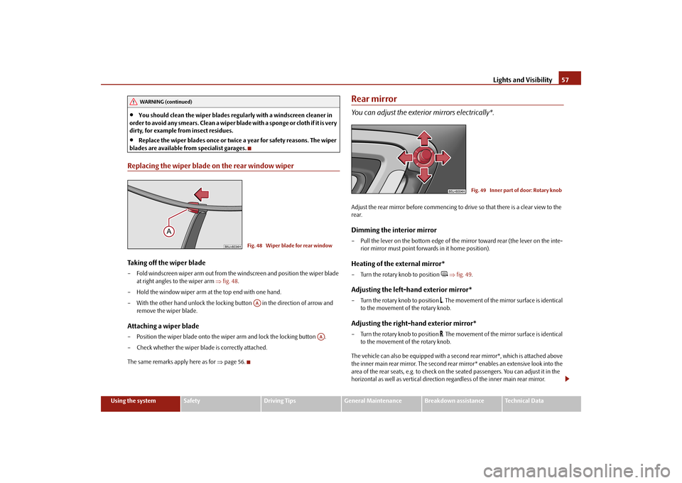
blades are available from specialist garages.Replacing the wiper blade on the rear window wiperTaking off the wiper blade– Fold windscreen wiper arm out from the windscreen and position the wiper blade
at right angles to the wiper arm
fig. 48
.
– Hold the window wiper arm at the top end with one hand.– With the other hand unlock the locking button in the direction of arrow and
remove the wiper blade.
Attaching a wiper blade– Position the wiper blade onto the wiper arm and lock the locking button . – Check whether the wiper bl
ade is correctly attached.
The same remarks apply here as for
page 56.
Rear mirrorYou can adjust the exterior mirrors electrically*.Adjust the rear mirror before commencing to drive so that there is a clear view to the rear.Dimming the interior mirror– Pull the lever on the bottom edge of the mirror toward rear (the lever on the inte-
rior mirror must point forwards in it home position).
Heating of the external mirror*– Turn the rotary knob to position
fig. 49
.
Adjusting the left-hand exterior mirror*– Turn the rotary knob to position
. The movement of the mirror surface is identical
to the movement of the rotary knob.
Adjusting the right-hand exterior mirror*– Turn the rotary knob to position
. The movement of the mirror surface is identical
to the movement of the rotary knob.
The vehicle can also be equipp
ed with a second rear mirror*, which is attached above
the inner main rear mirror. Th
e second rear mirror* enables an extensive look into the
area of the rear seats, e.g. to check on the seated passengers. You can adjust it in the horizontal as well as vertical direction re
gardless of the inner main rear mirror.
WARNING (continued)
Fig. 48 Wiper blade for rear windowAA
AA
Fig. 49 Inner part of door: Rotary knob
s3j8.a.book Page 57 Tuesday, April 20, 2010 1:10 PM
Page 60 of 244
Seats and Storage
59
Using the system
Safety
Driving Tips
General Maintenance
Breakdown assistance
Technical Data
Seats and StorageFront seatsBasic informationThe front seats have a wide range of differ
ent settings and can thus be matched to the
physical characteristics of the driver and
front passenger. Correct adjustment of the
seats is particularly important for:
safely and quickly reaching the controls;
a relaxed, fatigue-free body position;
achieving the maximum protection offered by the seat belts and the airbag
system. The chapters which follow describe the procedure which you should adopt for adjusting the seats.
WARNING
Never transport more occupants than the maximum seating in the vehicle.
Each occupant must correctly fasten the seat belt belonging to the seat.
Children must be fastened
page 130, “Transporting children safely” with a
suitable restraint system.
The front seats and the head restraints must always be adjusted to match
the body size of the seat occupant as well as the seat belts must always be correctly fastened in order to provide an optimal protection for you and your occupants.
Always keep your feet in the footwell
when the vehicle is being driven -
never place your feet on the instrument panel, out of the window or on the surfaces of the seats. This is particular
ly important for the front seat passenger.
You will be exposed to increased risk of
injury if it becomes necessary to apply
the brake or in the event of an accident.
If an airbag is deployed, you may suffer
fatal injuries when adopting an incorrect seated position!
It is important for the driver and front
passenger to maintain
a distance of at
least 25 cm from the steering wheel or
dash panel. Not maintaining this
minimum distance will mean that the airbag
system will not be able to properly
protect you - hazard! The front seats and the head restraints must always also be correctly adjusted to match the body size of the occupant.
Ensure that there are no objects in
the footwell as any objects may get
behind the pedals during a driving or braking manoeuvre. You would then no longer be able to operate the clutch, to brake or accelerate.
Do not transport any objects on the front passenger seat except those
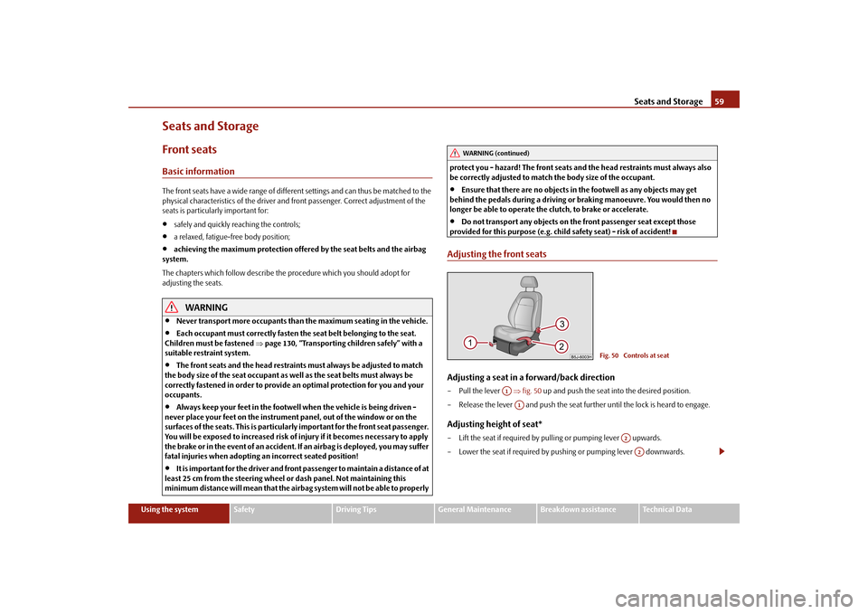
provided for this purpose (e.g. child safety seat) - risk of accident!Adjusting the front seatsAdjusting a seat in a forward/back direction–Pull the lever
fig. 50
up and push the seat into the desired position.
– Release the lever and push the seat further until the lock is heard to engage.Adjusting height of seat*– Lift the seat if required by pulling or pumping lever upwards.– Lower the seat if required by pushing or pumping lever downwards.
WARNING (continued)
Fig. 50 Controls at seat
A1A1
A2A2
s3j8.a.book Page 59 Tuesday, April 20, 2010 1:10 PM