ECU SKODA FABIA 2012 2.G / 5J User Guide
[x] Cancel search | Manufacturer: SKODA, Model Year: 2012, Model line: FABIA, Model: SKODA FABIA 2012 2.G / 5JPages: 196, PDF Size: 4.83 MB
Page 58 of 196
CAUTION
■ When closing the boot lid, jamming and damage to the luggage compartment
cover or the side trim panel can occur if handled in an unprofessional way. The
following guidelines must be observed. ■The mounts of the cover 3
» Fig. 47 must be interlocked in the holders of the
side trim panel 2
.
■ The items which are transported must not exceed the height of the luggage
compartment cover. ■ The cover must not be jammed in the seal of the boot lid when it is in the
opened position.
■ There must be no object in the gap between the opened cover and the rear
backrest. Note
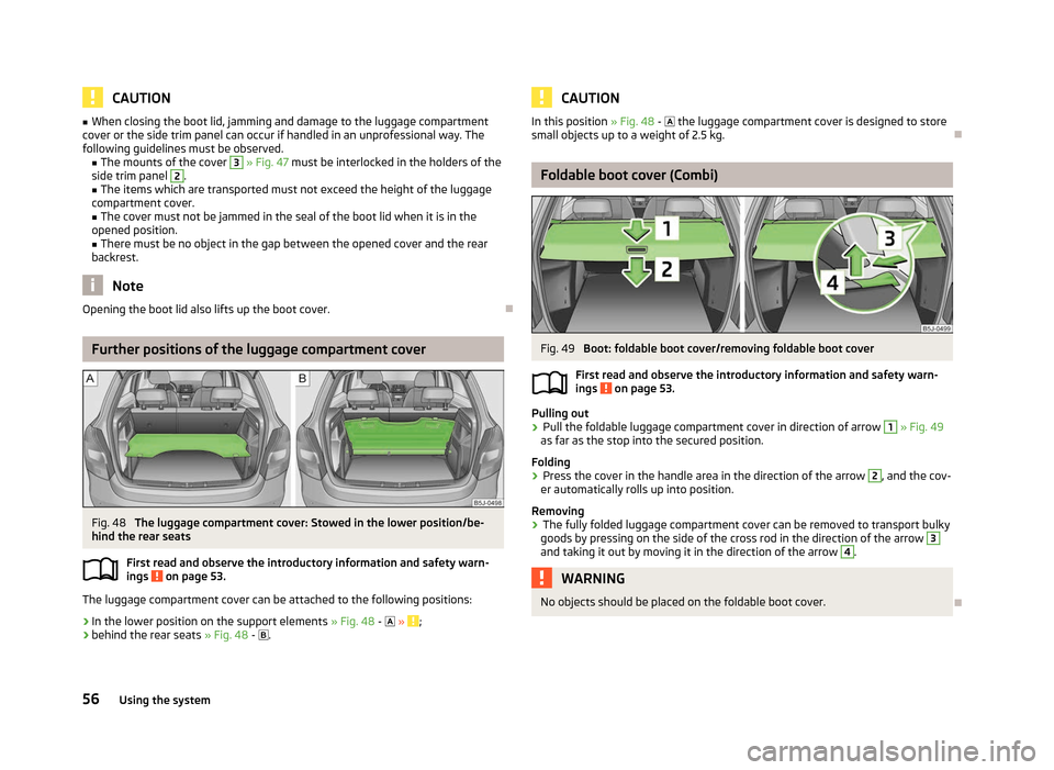
Opening the boot lid also lifts up the boot cover. ÐFurther positions of the luggage compartment cover
Fig. 48
The luggage compartment cover: Stowed in the lower position/be-
hind the rear seats
First read and observe the introductory information and safety warn-
ings on page 53.
The luggage compartment cover can be attached to the following positions:
› In the lower position on the support elements
» Fig. 48 - » ;
› behind the rear seats
» Fig. 48
- .
ä CAUTION
In this position » Fig. 48 - the luggage compartment cover is designed to store
small objects up to a weight of 2.5
kg. Ð Foldable boot cover (Combi)
Fig. 49
Boot: foldable boot cover/removing foldable boot cover
First read and observe the introductory information and safety warn-
ings on page 53.
Pulling out
›
Pull the foldable luggage compartment cover in direction of arrow 1
» Fig. 49
as far as the stop into the secured position.
Folding
› Press the cover in the handle area in the direction of the arrow 2
, and the cov-
er automatically rolls up into position.
Removing
› The fully folded luggage compartment cover can be removed to transport bulky
goods by pressing on the side of the cross rod in the direction of the arrow 3
and taking it out by moving it in the direction of the arrow 4
.
WARNING
No objects should be placed on the foldable boot cover. Ð
ä
56 Using the system
Page 59 of 196
Variable loading floor in the luggage compartment
(Combi) Introductory information
The variable loading floor makes handling of bulky items of luggage easier. CAUTION
The maximum permissible load of the variable loading floor is 75 kg.Note
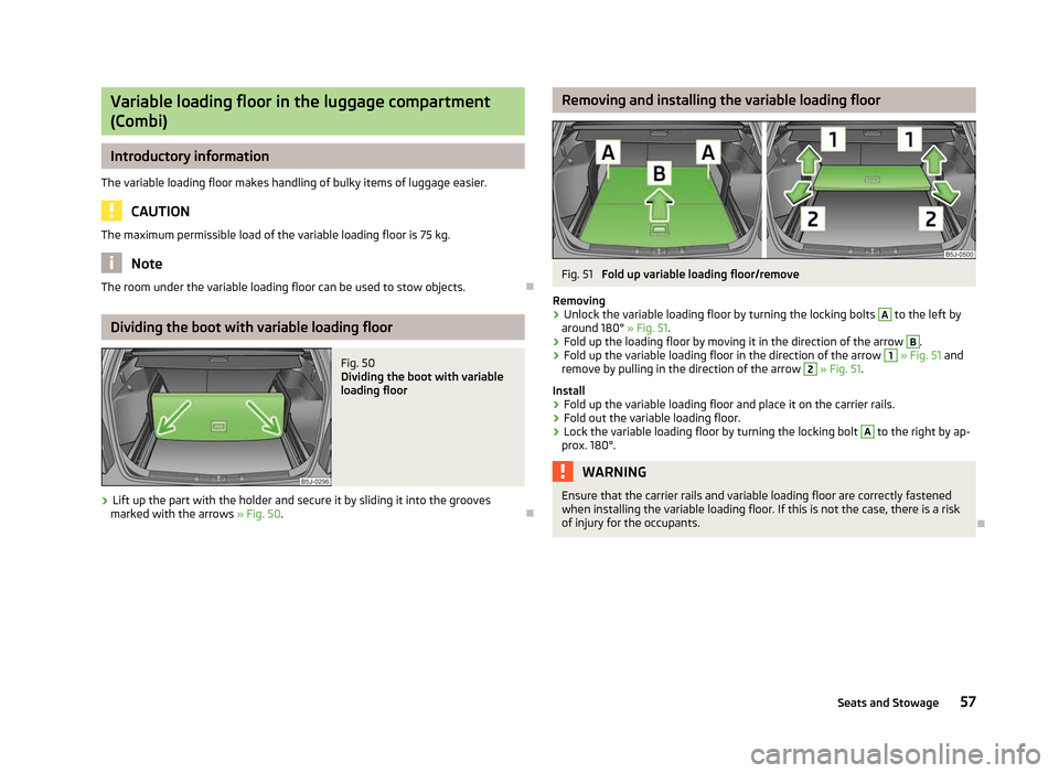
The room under the variable loading floor can be used to stow objects. ÐDividing the boot with variable loading floor
Fig. 50
Dividing the boot with variable
loading floor
› Lift up the part with the holder and secure it by sliding it into the grooves
marked with the arrows »
Fig. 50. Ð Removing and installing the variable loading floor
Fig. 51
Fold up variable loading floor/remove
Removing
› Unlock the variable loading floor by turning the locking bolts A
to the left by
around 180° » Fig. 51.
› Fold up the loading floor by moving it in the direction of the arrow B
.
› Fold up the variable loading floor in the direction of the arrow 1
» Fig. 51 and
remove by pulling in the direction of the arrow 2
» Fig. 51.
Install
› Fold up the variable loading floor and place it on the carrier rails.
› Fold out the variable loading floor.
› Lock the variable loading floor by turning the locking bolt A
to the right by ap-
prox. 180°. WARNING
Ensure that the carrier rails and variable loading floor are correctly fastened
when installing the variable loading floor. If this is not the case, there is a risk
of injury for the occupants. Ð
57
Seats and Stowage
Page 60 of 196
Removing and installing carrier rails
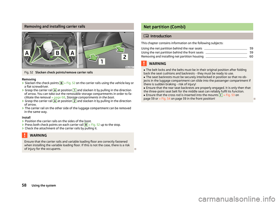
Fig. 52
Slacken check points/remove carrier rails
Removing
› Slacken the check points B
» Fig. 52
on the carrier rails using the vehicle key or
a flat screwdriver.
› Grasp the carrier rail A
at position 1
and slacken it by pulling in the direction
of arrow. You can take out the removable storage compartments in order to fa-
cilitate the removal » page 68 , Storage compartments in the boot .
› Grasp the carrier rail A
at position 2
and slacken it by pulling in the direction
of arrow.
› The carrier rail on the other side of the luggage compartment can be removed
in the same way.
Install
› Position the carrier rails on the sides of the boot.
› Press both check points on each carrier rail B
»
Fig. 52
up to the stop.
› Check the attachment of the carrier rails by pulling it. WARNING
Ensure that the carrier rails and variable loading floor are correctly fastened
when installing the variable loading floor. If this is not the case, there is a risk
of injury for the occupants. Ð Net partition (Combi)
ä
Introduction
This chapter contains information on the following subjects:
Using the net partition behind the rear seats 59
Using the net partition behind the front seats 59
Removing and installing net partition housing 60
WARNING
■ The belt locks and the belts must be in their original position after folding
back the seat cushions and backrests - they must be ready to use.
■ The seat backrests must be securely interlocked in position so that no ob-
jects in the luggage compartment can slide into the passenger compartment if
there is sudden braking - risk of injury!
■ Ensure that the rear seat backrests are properly engaged. It is only then that
the three-point seat belt for the middle seat can reliably fulfil its function. ■ Ensure that the cross rod is inserted into the mounts C
» Fig. 53 on
page 59
or » Fig. 54 on page 59 in the front position! Ð
58 Using the system
Page 61 of 196
Using the net partition behind the rear seats
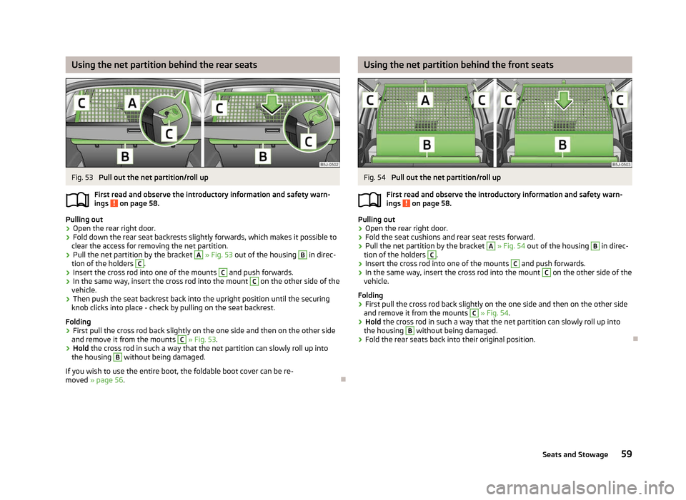
Fig. 53
Pull out the net partition/roll up
First read and observe the introductory information and safety warn-
ings on page 58.
Pulling out
› Open the rear right door.
› Fold down the rear seat backrests slightly forwards, which makes it possible to
clear the access for removing the net partition.
› Pull the net partition by the bracket A
» Fig. 53 out of the housing B
in direc-
tion of the holders C
.
› Insert the cross rod into one of the mounts C
and push forwards.
› In the same way, insert the cross rod into the mount C
on the other side of the
vehicle.
› Then push the seat backrest back into the upright position until the securing
knob clicks into place - check by pulling on the seat backrest.
Folding
› First pull the cross rod back slightly on the one side and then on the other side
and remove it from the mounts C
» Fig. 53.
› Hold the cross rod in such a way that the net partition can slowly roll up into
the housing B
without being damaged.
If you wish to use the entire boot, the foldable boot cover can be re-
moved » page 56 . Ð
ä Using the net partition behind the front seats
Fig. 54
Pull out the net partition/roll up
First read and observe the introductory information and safety warn-
ings on page 58.
Pulling out
› Open the rear right door.
› Fold the seat cushions and rear seat rests forward.
› Pull the net partition by the bracket A
» Fig. 54
out of the housing B
in direc-
tion of the holders C
.
› Insert the cross rod into one of the mounts C
and push forwards.
› In the same way, insert the cross rod into the mount C
on the other side of the
vehicle.
Folding
› First pull the cross rod back slightly on the one side and then on the other side
and remove it from the mounts C
» Fig. 54
.
› Hold the cross rod in such a way that the net partition can slowly roll up into
the housing B
without being damaged.
› Fold the rear seats back into their original position. Ð
ä
59
Seats and Stowage
Page 62 of 196

Removing and installing net partition housing
Fig. 55
Rear seats: Net partition hous-
ing
First read and observe the introductory information and safety warn-
ings on page 58.
Removing
› Open the rear right door.
› Fold the seat cushions and rear seat backrests forward – first the left and then
the right backrest.
› Push the net partition housing A
» Fig. 55 in the direction of the arrow 1
and
remove it from the mount on the right seat rest in the direction of the arrow 2
.
Install
› Insert the recesses on the net partition housing into the mounts on the rear
seat backrests.
› Push the net partition housing in the opposite direction of the arrow 1
as far
as the stop.
› Fold the rear seats back into their original position. ÐBicycle carrier in the luggage compartment
ä
Introduction
This chapter contains information on the following subjects:
Install cross member 60
Install bicycle carrier 61
Put bicycle into the bicycle carrier 61
Secure the stability of the bicycles with a belt 61
ä WARNING
When transporting bicycles, ensuring the safety of the passengers is para-
mount. CAUTION
Be careful when maneuvering the bicycle - risk of damage to the vehicle. Ð Install cross member
Fig. 56
Install cross member
First read and observe the introductory information and safety warn-
ings on page 60.
›
Remove the rollable luggage compartment cover
» page 56; if necessary we
recommend you remove the net partition » page 60.
› Remove the head rests from the rear seat rests and fold the rear seats for-
ward » page 52.
› Undo the securing screws C
» Fig. 56 and remove a little to unlock the holders B
.
› Place the cross member A
with the fixed part onto the left lashing eye and
then place it on the right lashing eye with the removable part of the cross mem-
ber A
.
› Press the holders B
until they latch. Tighten the securing screws C
.
› Check how well the cross member is fastened by pulling on it. Ð
ä
60 Using the system
Page 63 of 196
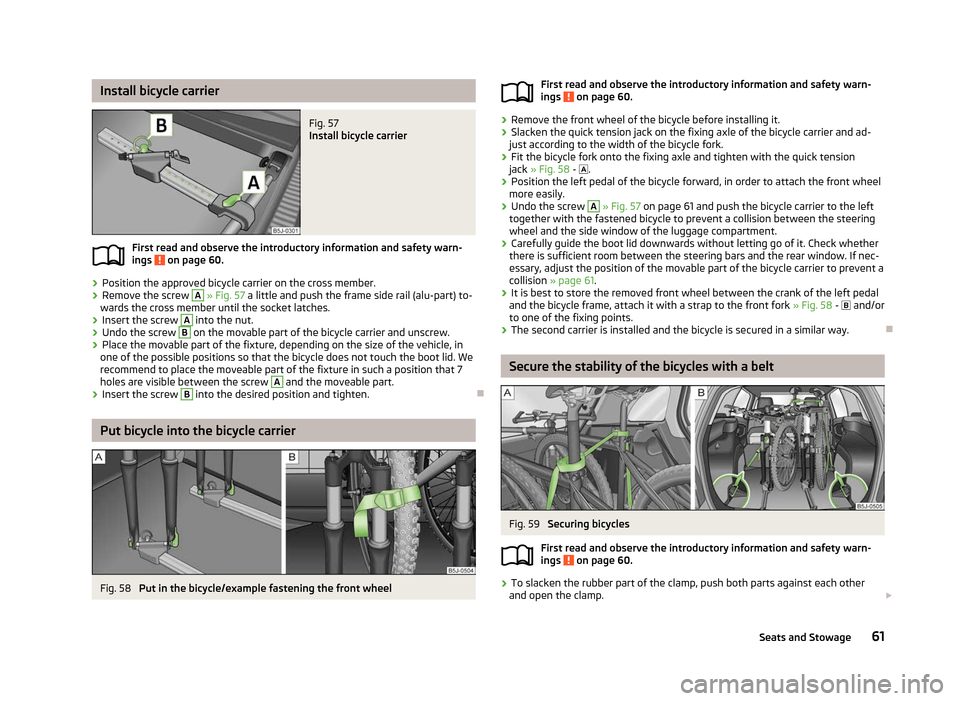
Install bicycle carrier
Fig. 57
Install bicycle carrier
First read and observe the introductory information and safety warn-
ings on page 60.
›
Position the approved bicycle carrier on the cross member.
› Remove the screw A
» Fig. 57 a little and push the frame side rail (alu-part) to-
wards the cross member until the socket latches.
› Insert the screw A
into the nut.
› Undo the screw B
on the movable part of the bicycle carrier and unscrew.
› Place the movable part of the fixture, depending on the size of the vehicle, in
one of the possible positions so that the bicycle does not touch the boot lid. We
recommend to place the moveable part of the fixture in such a position that 7
holes are visible between the screw A
and the moveable part.
› Insert the screw B
into the desired position and tighten.
ÐPut bicycle into the bicycle carrier
Fig. 58
Put in the bicycle/example fastening the front wheel
ä
First read and observe the introductory information and safety warn-
ings on page 60.
›
Remove the front wheel of the bicycle before installing it.
› Slacken the quick tension jack on the fixing axle of the bicycle carrier and ad-
just according to the width of the bicycle fork.
› Fit the bicycle fork onto the fixing axle and tighten with the quick tension
jack »
Fig. 58 - .
› Position the left pedal of the bicycle forward, in order to attach the front wheel
more easily.
› Undo the screw A
» Fig. 57 on page 61 and push the bicycle carrier to the left
together with the fastened bicycle to prevent a collision between the steering
wheel and the side window of the luggage compartment.
› Carefully guide the boot lid downwards without letting go of it. Check whether
there is sufficient room between the steering bars and the rear window. If nec-
essary, adjust the position of the movable part of the bicycle carrier to prevent a
collision » page 61.
› It is best to store the removed front wheel between the crank of the left pedal
and the bicycle frame, attach it with a strap to the front fork » Fig. 58 - and/or
to one of the fixing points.
› The second carrier is installed and the bicycle is secured in a similar way. Ð Secure the stability of the bicycles with a belt
Fig. 59
Securing bicycles
First read and observe the introductory information and safety warn-
ings on page 60.
›
To slacken the rubber part of the clamp, push both parts against each other
and open the clamp. £
ä
ä 61
Seats and Stowage
Page 64 of 196
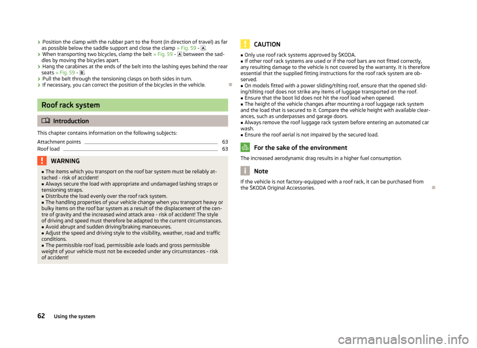
›
Position the clamp with the rubber part to the front (in direction of travel) as far
as possible below the saddle support and close the clamp » Fig. 59
- .
› When transporting two bicycles, clamp the belt
» Fig. 59 - between the sad-
dles by moving the bicycles apart.
› Hang the carabines at the ends of the belt into the lashing eyes behind the rear
seats » Fig. 59 - .
› Pull the belt through the tensioning clasps on both sides in turn.
› If necessary, you can correct the position of the bicycles in the vehicle. ÐRoof rack system
ä
Introduction
This chapter contains information on the following subjects:
Attachment points 63
Roof load 63
WARNING
■ The items which you transport on the roof bar system must be reliably at-
tached - risk of accident!
■ Always secure the load with appropriate and undamaged lashing straps or
tensioning straps. ■ Distribute the load evenly over the roof rack system.
■ The handling properties of your vehicle change when you transport heavy or
bulky items on the roof bar system as a result of the displacement of the cen-
tre of gravity and the increased wind attack area - risk of accident! The style
of driving and speed must therefore be adapted to the current circumstances. ■ Avoid abrupt and sudden driving/braking manoeuvres.
■ Adjust the speed and driving style to the visibility, weather, road and traffic
conditions. ■ The permissible roof load, permissible axle loads and gross permissible
weight of your vehicle must not be exceeded under any circumstances - risk
of accident! CAUTION
■ Only use roof rack systems approved by
ŠKODA.
■ If other roof rack systems are used or if the roof bars are not fitted correctly,
any resulting damage to the vehicle is not covered by the warranty. It is therefore
essential that the supplied fitting instructions for the roof rack system are ob-
served.
■ On models fitted with a power sliding/tilting roof, ensure that the opened slid-
ing/tilting roof does not strike any items of luggage transported on the roof. ■ Ensure that the boot lid does not hit the roof load when opened.
■ The height of the vehicle changes after mounting a roof luggage rack system
and the load that is secured to it. Compare the vehicle height with available clear-
ances, such as underpasses and garage doors.
■ Always remove the roof luggage rack system before entering an automated car
wash. ■ Ensure the roof aerial is not impaired by the secured load. For the sake of the environment
The increased aerodynamic drag results in a higher fuel consumption. Note
If the vehicle is not factory-equipped with a roof rack, it can be purchased from
the
ŠKODA Original Accessories. Ð
62 Using the system
Page 99 of 196

Inserting the mobile phone and adapter
Fig. 93
Universal telephone preinstalla-
tion
Only one telephone mount is factory-fitted. An adapter for the mobile phone can
be purchased from ŠKODA Original Accessories.
Install › First of all push the adapter A
in the direction of the arrow
» Fig. 93
up to the
stop into the mount. Then press the adapter slightly downwards, until it locks
securely into position.
› Insert the mobile phone into the adapter A
(as specified in the instructions
from the manufacturer of the adapter).
Removing
› Simultaneously press the locks on the mount
» Fig. 93 and remove the adapter
with the mobile phone. CAUTION
Taking the mobile phone out of the adapter during the call can lead to interrup-
tion of the connection. When removing the mobile phone, the connection to the
factory-fitted antenna is interrupted, which reduces the quality of the transmit-
ting and receiving signal. The charging of the mobile phone battery is also inter-
rupted. Ð Managing telephone calls with the help of the adapter
Fig. 94
Principle sketch: Adapter with one button/adapter with two buttons
Function overview of the »
Fig. 94
(PTT - “push to talk”) button on the adapter:
› Switch on/off voice control;
› Accept/end a call.
Some adapters include the button SOS A
» Fig. 94
in addition to the button .
After pressing this button for 2
seconds, the number 112 (Emergency call) is dial-
led. Ð Connecting the mobile phone to the hands-free system
To connect a mobile phone with the hands-free system, the two devices must be
paired. Detailed information on this is provided in the operating instructions for
your mobile phone.
The following steps must be carried out for the connection.
› Activate Bluetooth ®
and the visibility of your mobile phone on your telephone.
› Switch on the ignition.
› Select the menu
Phone - New user in the information display and wait until the
control unit has completed the search.
› Select your mobile phone from the menu of the units found.
› Confirm the PIN 1)
. £1)
Depending on the Bluetooth ®
version on the mobile phone, an automatically generated 6-digit PIN is
either displayed or the PIN 1234 has to be entered manually.
97
Communication
Page 105 of 196
Safety
Passive Safety
General information
ä
Introduction
This chapter contains information on the following subjects:
Safety equipment 103
Before setting off 103
What influences the driving safety? 104
In this section you will find important information, tips and notes on the subject
of passive safety in your vehicle. We have combined everything here which you
should be familiar with, for example, regarding seat belts, airbags, child seats and
safety of children. It is therefore important, in particular, to comply with the notes
and warnings in this section for your own interest and in the interest of those
travelling with you. WARNING
■ This chapter contains important information on how to use the vehicle for
the driver and his occupants. You will find further information on safety, which
concerns you and those travelling with you, in the following chapters of this
Owner's Manual.
■ The complete on-board literature should always be in the vehicle. This ap-
plies in particular, if you rent out or sell the vehicle. ÐSafety equipment
First read and observe the introductory information and safety warn-
ings on page 103.
The following list contains part of the safety equipment in your vehicle:
› three-point seat belts for all the seats;
› belt force limiters for the front seats;
ä ›
belt tensioners for front seats;
› seat belt height adjusters for front seats;
› Front airbag for the driver and the front seat passenger;
› side airbags;
› head airbags;
› anchoring points for child seat using the
ISOFIX system;
› anchoring points for child seat using the TOP TETHER system;
› head restraints adjustable for height;
› adjustable steering column.
The specified safety equipment works together, in order to optimally protect you
and those travelling with you in accident situations. The safety equipment does
not protect you or the people travelling with you, if you or your occupants adopt
an incorrect seated position or the equipment is not correctly adjusted or used. Ð Before setting off
First read and observe the introductory information and safety warn-
ings on page 103.
For your own safety and the safety of the people travelling with you, please pay
attention to the following points before setting off.
›
Ensure that the lighting and the turn signal system are functioning properly.
› Check the tyre inflation pressure.
› Ensure that all of the windows offer good visibility to the outside.
› Secure all items of luggage
» page 53.
› Ensure that no objects can obstruct the pedals.
› Adjust the mirrors, the front seat and head restraint to your body size.
› Advise your passengers to adjust the head restraints to their body size.
› Protect children in suitable child seats with correctly fastened seat
belts
» page 117 , Transporting children safely .
› Adopt the correct seated position
» page 104. Tell your passengers to assume
the correct seated position.
› Correctly fasten the seat belt. Also inform passengers to fasten the seat belt
correctly » page 107. Ð
ä
103
Passive Safety
Page 120 of 196

The following guidelines must be observed when using a child safety seat in
which the child is seated with its back facing the direction of travel on the front
passenger seat.
›
Switch off the front passenger airbag
» page 115, Deactivating airbags .
› Slide the front passenger seat all the way back.
› Move the front passenger seat backrest into the vertical position.
› Set the height-adjustable front passenger seat as high up as possible.
› Set the front passenger seat belt as high up as possible.
› Place and fasten the child seat on the seat and the child in the child seat ac-
cording to the specifications in the manufacturer's user manual of the child
seat . WARNING
■ It is essential to always switch off the front passenger airbag when attach-
ing a child safety seat to the front passenger seat where the child is seated
with its back facing in direction of travel » page 115, Deactivating airbags.
■ Never use a child safety seat in which the child is seated with its back facing
the direction of travel on the front passenger seat if the airbag is switched on.
This child safety seat is positioned in the deployment area of the front pas-
senger airbag. The airbag may cause the child severe, or even fatal injuries, in
the event of it being deployed.
■ This is also clearly stated on the sticker which is located on the B column on
the front passenger side » Fig. 107 or on the front passenger's sun visor.
■ If a child safety seat in which the child faces in the direction of travel is used
on the front passenger seat, the front passenger seat must be moved back
and to the top fully. Move the backrest into the vertical position.
■ The front passenger airbag must be reactivated as soon as you no longer
use a child seat on the front passenger seat. Ð Child safety and side airbag
Fig. 108
Incorrect seated position of a child who is not properly secured -
risk from the side airbag/Child properly protected by safety seat
First read and observe the introductory information and safety warn-
ings on page 117.
The child must not be positioned in the deployment area of the side air-
bag » Fig. 108
- . There must be sufficient room between the child and the de-
ployment area of the side airbag so that the airbag can provide as much protec-
tion as possible » Fig. 108 - . WARNING
■ Children must never be seated with their head in the deployment area of
the side airbag - risk of injury!
■ Do not place any objects within the deployment area of the side airbags -
risk of injury! Ð Classification of child seats
First read and observe the introductory information and safety warn-
ings on page 117.
Child safety seats are classified in 5 groups:
Group Weight of the child Approximate age
0 0-10 kg up to 9 months
0+ up to 13 kg up to 18 months£ ä
ä
118 Safety