locking SKODA FABIA 2012 2.G / 5J User Guide
[x] Cancel search | Manufacturer: SKODA, Model Year: 2012, Model line: FABIA, Model: SKODA FABIA 2012 2.G / 5JPages: 196, PDF Size: 4.83 MB
Page 35 of 196
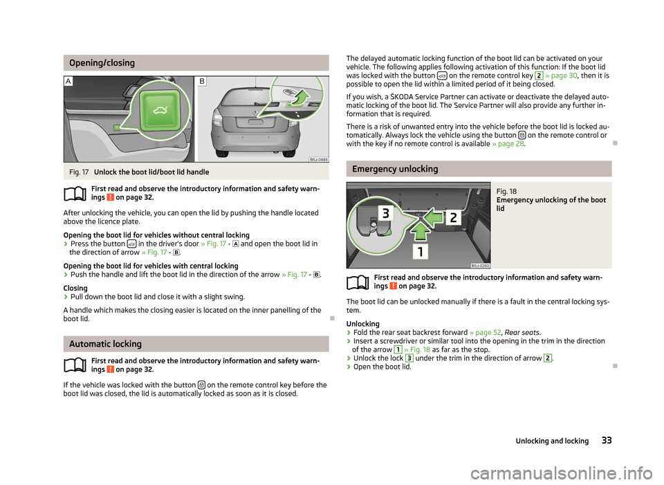
Opening/closing
Fig. 17
Unlock the boot lid/boot lid handle
First read and observe the introductory information and safety warn-
ings on page 32.
After unlocking the vehicle, you can open the lid by pushing the handle located
above the licence plate.
Opening the boot lid for vehicles without central locking
›
Press the button
in the driver's door
» Fig. 17 - and open the boot lid in
the direction of arrow » Fig. 17 - .
Opening the boot lid for vehicles with central locking › Push the handle and lift the boot lid in the direction of the arrow
» Fig. 17 - .
Closing
› Pull down the boot lid and close it with a slight swing.
A handle which makes the closing easier is located on the inner panelling of the
boot lid. ÐAutomatic locking
First read and observe the introductory information and safety warn-
ings on page 32.
If the vehicle was locked with the button
on the remote control key before the
boot lid was closed, the lid is automatically locked as soon as it is closed.
ä
ä The delayed automatic locking function of the boot lid can be activated on your
vehicle. The following applies following activation of this function: If the boot lid
was locked with the button on the remote control key 2
» page 30, then it is
possible to open the lid within a limited period of it being closed.
If you wish, a
ŠKODA Service Partner can activate or deactivate the delayed auto-
matic locking of the boot lid. The Service Partner will also provide any further in-
formation that is required.
There is a risk of unwanted entry into the vehicle before the boot lid is locked au-
tomatically. Always lock the vehicle using the button on the remote control or
with the key if no remote control is available » page 28 .Ð Emergency unlocking
Fig. 18
Emergency unlocking of the boot
lid
First read and observe the introductory information and safety warn-
ings on page 32.
The boot lid can be unlocked manually if there is a fault in the central locking sys-
tem.
Unlocking
›
Fold the rear seat backrest forward
» page 52, Rear seats.
› Insert a screwdriver or similar tool into the opening in the trim in the direction
of the arrow 1
» Fig. 18 as far as the stop.
› Unlock the lock 3
under the trim in the direction of arrow 2
.
› Open the boot lid. Ð
ä
33
Unlocking and locking
Page 37 of 196
›
Additionally, the window can be closed automatically (fully closed) by pulling
the button to the stop. Renewed pulling of the button causes the window to
stop immediately.
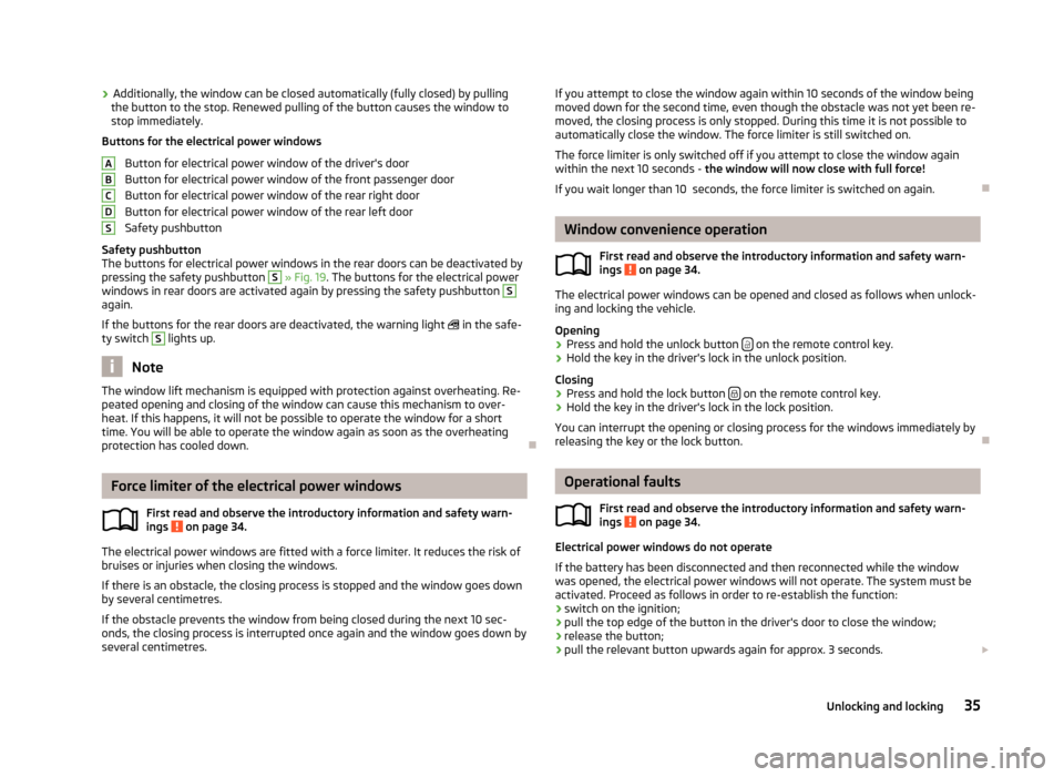
Buttons for the electrical power windows
Button for electrical power window of the driver's door
Button for electrical power window of the front passenger door
Button for electrical power window of the rear right door
Button for electrical power window of the rear left door
Safety pushbutton
Safety pushbutton
The buttons for electrical power windows in the rear doors can be deactivated by
pressing the safety pushbutton S
» Fig. 19
. The buttons for the electrical power
windows in rear doors are activated again by pressing the safety pushbutton S
again.
If the buttons for the rear doors are deactivated, the warning light
in the safe-
ty switch S
lights up.
Note
The window lift mechanism is equipped with protection against overheating. Re-
peated opening and closing of the window can cause this mechanism to over-
heat. If this happens, it will not be possible to operate the window for a short
time. You will be able to operate the window again as soon as the overheating
protection has cooled down. ÐForce limiter of the electrical power windows
First read and observe the introductory information and safety warn-
ings on page 34.
The electrical power windows are fitted with a force limiter. It reduces the risk of
bruises or injuries when closing the windows.
If there is an obstacle, the closing process is stopped and the window goes down
by several centimetres.
If the obstacle prevents the window from being closed during the next 10 sec-
onds, the closing process is interrupted once again and the window goes down by
several centimetres. A
B
C
D
S
ä If you attempt to close the window again within 10 seconds of the window being
moved down for the second time, even though the obstacle was not yet been re-
moved, the closing process is only stopped. During this time it is not possible to
automatically close the window. The force limiter is still switched on.
The force limiter is only switched off if you attempt to close the window again
within the next 10
seconds - the window will now close with full force!
If you wait longer than 10 seconds, the force limiter is switched on again. Ð Window convenience operation
First read and observe the introductory information and safety warn-
ings on page 34.
The electrical power windows can be opened and closed as follows when unlock-
ing and locking the vehicle.
Opening
› Press and hold the unlock button
on the remote control key.
› Hold the key in the driver's lock in the unlock position.
Closing
› Press and hold the lock button
on the remote control key.
› Hold the key in the driver's lock in the lock position.
You can interrupt the opening or closing process for the windows immediately by
releasing the key or the lock button. Ð Operational faults
First read and observe the introductory information and safety warn-
ings on page 34.
Electrical power windows do not operate
If the battery has been disconnected and then reconnected while the window
was opened, the electrical power windows will not operate. The system must be
activated. Proceed as follows in order to re-establish the function:
›
switch on the ignition;
› pull the top edge of the button in the driver's door to close the window;
› release the button;
› pull the relevant button upwards again for approx. 3
seconds.£
ä
ä
35
Unlocking and locking
Page 39 of 196
WARNING
Close the sliding/tilting roof carefully - risk of injury! The force limiter does not
operate with the convenience closing. ÐEmergency operation
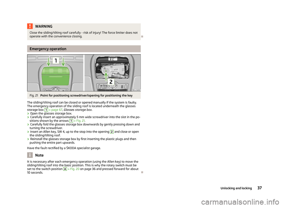
Fig. 21
Point for positioning screwdriver/opening for positioning the key
The sliding/tilting roof can be closed or opened manually if the system is faulty.
The emergency operation of the sliding roof is located underneath the glasses
storage box 1
» page 67,
Glasses storage box .
› Open the glasses storage box.
› Carefully insert an approximately 5 mm wide screwdriver into the slot in the po-
sitions shown by the arrows 1
» Fig. 21.
› Carefully fold the glasses storage box downwards by gently pressing down and
turning the screwdriver.
› Insert an Allen key, SW 4, up to the stop into the opening 2
and close or open
the sliding/tilting roof.
› Reinstall the glasses storage box by first inserting the plastic plugs and then
pushing the entire part upwards.
Have the fault rectified by a
ŠKODA specialist garage.Note
It is necessary after each emergency operation (using the Allen key) to move the
sliding/tilting roof into the basic position. This is why the rotary switch must be
set to the switch position A
» Fig. 20 on page 36 and pressed forward for about
10 seconds. Ð 37
Unlocking and locking
Page 45 of 196
Note
■ The turn signal system only operates when the ignition is switched on. The cor-
responding warning light or in the instrument cluster also flashes.
■ The turn signal is automatically cancelled after negotiating a curve.
■ The warning light flashes at twice its normal rate if a bulb for the turn signal
light fails. ÐInterior light
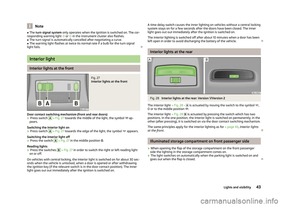
Interior lights at the front
Fig. 27
Interior lights at the front
Door contact switching mechanism (front and rear doors) › Press switch A
» Fig. 27 towards the middle of the light, the symbol
ap-
pears.
Switching the interior light on
› Press switch A
» Fig. 27 towards the edge of the light, the symbol
appears.
Switching the interior light off
› Press the switch A
» Fig. 27 in the middle position
O.
Reading lights
› Press the switches B
» Fig. 27 in order to switch the right or left reading light
on or off.
On vehicles with central locking, the interior light is switched on for about 30 sec-
onds when the vehicle is unlocked, when a door is opened or after withdrawing
the ignition key (if the relevant switch is in the door contact position). The inner
light goes out out immediately after the ignition is switched on. A time delay switch causes the inner lighting on vehicles without a central locking
system stays on for a few seconds after the doors have been closed. The inner
light goes out out immediately after the ignition is switched on.
The interior lighting is switched off after about 10 minutes when a door has been
left open in order to avoid discharging the battery of the vehicle. Ð Interior lights at the rear
Fig. 28
Interior lights at the rear: Version 1/Version 2
The interior light » Fig. 28 -
is actuated by moving the switch to the symbol ,
O or to the middle position .
The interior light » Fig. 28 is actuated by pressing the switch which has two
positions. In the one position, the interior light is switched on permanently; in the
other (after pressing), it is switched on via the door contact switching mechanism.
The same principles apply for the interior lighting as for » page 43, Interior lights
at the front . Ð Illuminated storage compartment on front passenger side
› When opening the flap of the storage compartment on the front passenger
side the lighting in the storage compartment comes on.
› The light switches on automatically when the parking light is switched on and
goes out when the flap is closed. Ð
43
Lights and visibility
Page 48 of 196
›
Release the lever. The washer system stops and the wiper continues for anoth-
er 1 to 3 wiper strokes (depending on the duration of the spraying process). The
lever will stay in position after releasing it 6
.
Switching windscreen wipers off
› Move the lever back into the home position 0
» Fig. 31.
ÐHeadlight cleaning system
First read and observe the introductory information and safety warn-
ings on page 44.
When the low beam or main beam are switched on, and the windscreen wiper
lever is pulled into the position
5
» Fig. 31 on page 45, the headlights are sprayed
briefly. To clean the headlights, the windshield is also sprayed after every five
squirts.
You should remove stubborn dirt (such as insect residues) from the headlight len-
ses at regular intervals, for example when refuelling. The following guidelines
must be observed » page 132, Headlight lenses .
To ensure the proper operation of the cleaning system during the winter, any
snow should be removed from the washer nozzle fixtures and ice should be
cleared with a de-icing spray. CAUTION
Never remove the nozzles from the headlight cleaning system by hand - risk of
damage! ÐReplacing the windscreen wiper blades
Fig. 32
Windscreen wiper blade
ä
First read and observe the introductory information and safety warn-
ings on page 44.
Removing the wiper blade
›
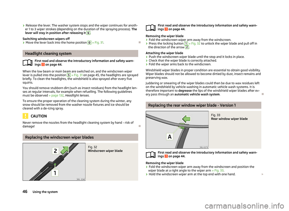
Fold the windscreen wiper arm away from the windscreen.
› Press the locking button 1
» Fig. 32 to unlock the wiper blade and pull off in
the direction of the arrow 2
.
Attaching the wiper blade
› Push the windscreen wiper blade until the stop and it locks in place.
› Check that the wiper blade is correctly attached.
› Fold the wiper arms back to the windscreen.
Windshield wiper blades in proper condition are essential to obtain good visibility.
Wiper blades should not be allowed to become dirtied by dust, insect remains and
preserving wax.
Juddering or smearing of the wiper blades could then be due to wax residues left
on the windshield by vehicle washing in automatic vehicle wash systems. It is
therefore important to degrease the lips of the windshield wiper blades after ev-
ery pass through an automatic vehicle wash system .Ð Replacing the rear window wiper blade - Version 1
Fig. 33
Rear window wiper blade
First read and observe the introductory information and safety warn-
ings on page 44.
Removing the wiper blade
›
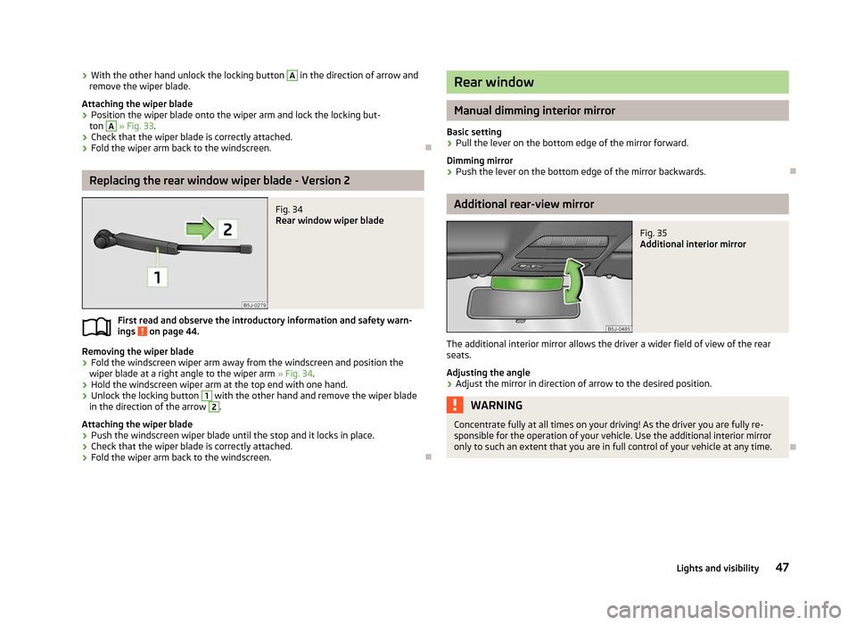
Fold the windscreen wiper arm away from the windscreen and position the
wiper blade at a right angle to the wiper arm » Fig. 33.
› Hold the windscreen wiper arm at the top end with one hand.
£
ä
ä
46 Using the system
Page 49 of 196
›
With the other hand unlock the locking button A
in the direction of arrow and
remove the wiper blade.
Attaching the wiper blade
› Position the wiper blade onto the wiper arm and lock the locking but-
ton A
» Fig. 33
.
› Check that the wiper blade is correctly attached.
› Fold the wiper arm back to the windscreen. ÐReplacing the rear window wiper blade - Version 2
Fig. 34
Rear window wiper blade
First read and observe the introductory information and safety warn-
ings on page 44.
Removing the wiper blade
›
Fold the windscreen wiper arm away from the windscreen and position the
wiper blade at a right angle to the wiper arm » Fig. 34.
› Hold the windscreen wiper arm at the top end with one hand.
› Unlock the locking button 1
with the other hand and remove the wiper blade
in the direction of the arrow 2
.
Attaching the wiper blade
› Push the windscreen wiper blade until the stop and it locks in place.
› Check that the wiper blade is correctly attached.
› Fold the wiper arm back to the windscreen. Ð
ä Rear window
Manual dimming interior mirror
Basic setting
› Pull the lever on the bottom edge of the mirror forward.
Dimming mirror
› Push the lever on the bottom edge of the mirror backwards. Ð Additional rear-view mirror
Fig. 35
Additional interior mirror
The additional interior mirror allows the driver a wider field of view of the rear
seats.
Adjusting the angle › Adjust the mirror in direction of arrow to the desired position. WARNING
Concentrate fully at all times on your driving! As the driver you are fully re-
sponsible for the operation of your vehicle. Use the additional interior mirror
only to such an extent that you are in full control of your vehicle at any time. Ð
47
Lights and visibility
Page 53 of 196
WARNING
If, as an occupant, you have a subdued pain and/or temperature sensitivity,
e.g. through medication, paralysis or because of chronic illness (e.g. diabetes),
we recommend not to use the seat heating. This can lead to burns on the
back, the posterior and the legs which are difficult to heal. If the seat heating
is used, we recommend to make regular breaks in your journey when driving
long distances, so that the body can recuperate from the stress of the jour-
ney. Please consult your doctor, who can evaluate your specific condition. CAUTION
■ Do not kneel on the seats or otherwise apply pressure at specific points to
avoid damaging the heating elements for the seat heaters.
■ Do not use the seat heaters if the seats are not occupied by persons or if ob-
jects, such as a child seat, bag, etc., are fastened or stored on them. A fault of the
heating elements in the seat heating can occur.
■ Do not clean the seats using moisture » page 134. Note
■ The seat heating should only be switched on when the engine is running. This
has a significant effect of saving on the battery capacity. ■ If the on-board voltage drops, the seat heating is switched off automatically, in
order to provide sufficient electrical energy for the engine control » page 149, Au-
tomatic load deactivation . ÐHead restraints
Fig. 40
Head restraint: adjusting/removing Adjusting the height of a head restraint
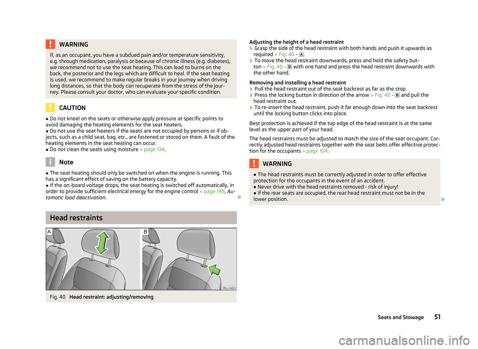
› Grasp the side of the head restraint with both hands and push it upwards as
required » Fig. 40 - .
› To move the head restraint downwards, press and hold the safety but-
ton » Fig. 40 - with one hand and press the head restraint downwards with
the other hand.
Removing and installing a head restraint
› Pull the head restraint out of the seat backrest as far as the stop.
› Press the locking button in direction of the arrow
» Fig. 40 - and pull the
head restraint out.
› To re-insert the head restraint, push it far enough down into the seat backrest
until the locking button clicks into place.
Best protection is achieved if the top edge of the head restraint is at the same
level as the upper part of your head.
The head restraints must be adjusted to match the size of the seat occupant. Cor-
rectly adjusted head restraints together with the seat belts offer effective protec-
tion for the occupants » page 104. WARNING
■ The head restraints must be correctly adjusted in order to offer effective
protection for the occupants in the event of an accident. ■ Never drive with the head restraints removed - risk of injury!
■ If the rear seats are occupied, the rear head restraint must not be in the
lower position. Ð
51
Seats and Stowage
Page 59 of 196
Variable loading floor in the luggage compartment
(Combi) Introductory information
The variable loading floor makes handling of bulky items of luggage easier. CAUTION
The maximum permissible load of the variable loading floor is 75 kg.Note
The room under the variable loading floor can be used to stow objects. ÐDividing the boot with variable loading floor
Fig. 50
Dividing the boot with variable
loading floor
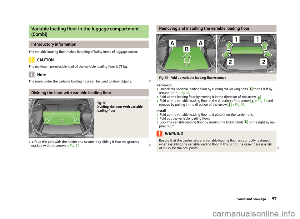
› Lift up the part with the holder and secure it by sliding it into the grooves
marked with the arrows »
Fig. 50. Ð Removing and installing the variable loading floor
Fig. 51
Fold up variable loading floor/remove
Removing
› Unlock the variable loading floor by turning the locking bolts A
to the left by
around 180° » Fig. 51.
› Fold up the loading floor by moving it in the direction of the arrow B
.
› Fold up the variable loading floor in the direction of the arrow 1
» Fig. 51 and
remove by pulling in the direction of the arrow 2
» Fig. 51.
Install
› Fold up the variable loading floor and place it on the carrier rails.
› Fold out the variable loading floor.
› Lock the variable loading floor by turning the locking bolt A
to the right by ap-
prox. 180°. WARNING
Ensure that the carrier rails and variable loading floor are correctly fastened
when installing the variable loading floor. If this is not the case, there is a risk
of injury for the occupants. Ð
57
Seats and Stowage
Page 81 of 196
Starting-off and Driving
Starting and stopping the engine
ä
Introduction
This chapter contains information on the following subjects:
Adjusting the steering wheel position 80
Electrohydraulic power steering 80
Electronic immobiliser 80
Ignition lock 81
Starting engine 81
Switching off the engine 81
WARNING
■ Never adjust the steering wheel when the vehicle is moving only when the
vehicle is stationary!
■ Maintain a distance of 25 cm 1
to the steering wheel
» Fig. 81 on page 80
- . Not maintaining this minimum distance will mean that the airbag system
will not be able to properly protect you - hazard!
■ The lever for adjusting the steering wheel must be locked whilst driving so
that the position of the steering wheel cannot accidently change during the
journey - risk of accident!
■ If the steering wheel is adjusted further towards the head, the protection
provided by the driver airbag in the event of an accident is reduced. Check
that the steering wheel is aligned to the chest. ■ When driving, hold the steering wheel with both hands firmly on the outer
edge in the 9 o'clock and 3 o'clock position. Never hold the steering wheel in
the 12 o'clock position or in any other way (e.g. in the middle or inner edge of
the steering wheel). In such cases, you could injure the arms, hands and head
when the driver airbag is deployed.
■ When driving, the ignition key must always be in the position 2
» Fig. 82 on
page 81 (ignition switched on) without the engine running. This position is
indicated by the warning lights coming on. If this is not the case, it could result
in unexpected locking of the steering wheel - risk of accident! WARNING (Continued)
■ Only pull the ignition key from the ignition lock when the vehicle has come
to a complete stop (by applying the handbrake). Otherwise the steering wheel
could block - risk of accident!
■ When leaving the vehicle, the ignition must always be removed. This is par-
ticularly important if children are left in the vehicle. Otherwise the children
could, for example, start the engine - risk of accident or injury!
■ Never leave the engine running in unventilated or closed rooms. The ex-
haust gases of the engine contain besides the odorless and colourless carbon
monoxide a poisonous gas - hazard! Carbon monoxide can cause unconscious-
ness and death. ■ Never leave the vehicle unattended with the engine running.
■ Never switch off the engine before the vehicle is stationary - risk of acci-
dent! CAUTION
■ You will place great stresses on the power steering system if the steering is
turned to full lock when the vehicle is stationary. Turning the steering to full lock
in such a situation will be accompanied by noises. Never leave the steering wheel
at full lock for more than 15
seconds when the engine is running - risk of damag-
ing the power steering!
■ The starter may only be operated (ignition key position 3
» Fig. 82 on
page 81), if the engine is not running. The starter or engine can be damaged if
the starter is activated when the engine is running. ■ Let go of the ignition key as soon as the engine starts otherwise the starter
could be damaged. ■ Avoid high engine revolutions, full throttle and high engine loads as long as the
engine has not yet reached its operating temperature - risk of damaging the en-
gine!
■ Do not tow start the engine - danger of damaging the engine! On vehicles with
a catalytic converter, unburnt fuel may get into the catalytic converter where it
may ignite. This in turn may damage the catalytic converter. The battery from an-
other vehicle can be used as a jump-start aid » page 165, Jump-starting.
■ Do not switch the engine off immediately at the end of your journey after the
engine has been operated over a prolonged period at high loads but leave it to
run at an idling speed for about 1
minute. This prevents any possible accumulation
of heat when the engine is switched off. £
79
Starting-off and Driving
Page 82 of 196
For the sake of the environment
Do not warm up the engine while the vehicle is stationary. If possible, start your
journey as soon as the engine has started. Through this the engine reaches its
operating temperature more rapidly and the pollutant emissions are lower. Note
■ The engine can only be started with a genuine ŠKODA key with the matching
code. ■ The engine running noises may louder at first be louder for a short time after
starting the cold engine. This is quite normal and is not an operating problem. ■ After switching off the ignition, the radiator fan can intermittently continue to
operate for approx. 10
minutes.
■ If the engine does not start up after a second attempt, the fuse for the fuel
pump may have a fault. Check the fuse and replace, if necessary » page 168,
Fuses or seek assistance from a
ŠKODA specialist garage.
■ We recommend locking the steering wheel whenever leaving the vehicle. This
acts as a deterrent against the attempted theft of your car. ÐAdjusting the steering wheel position
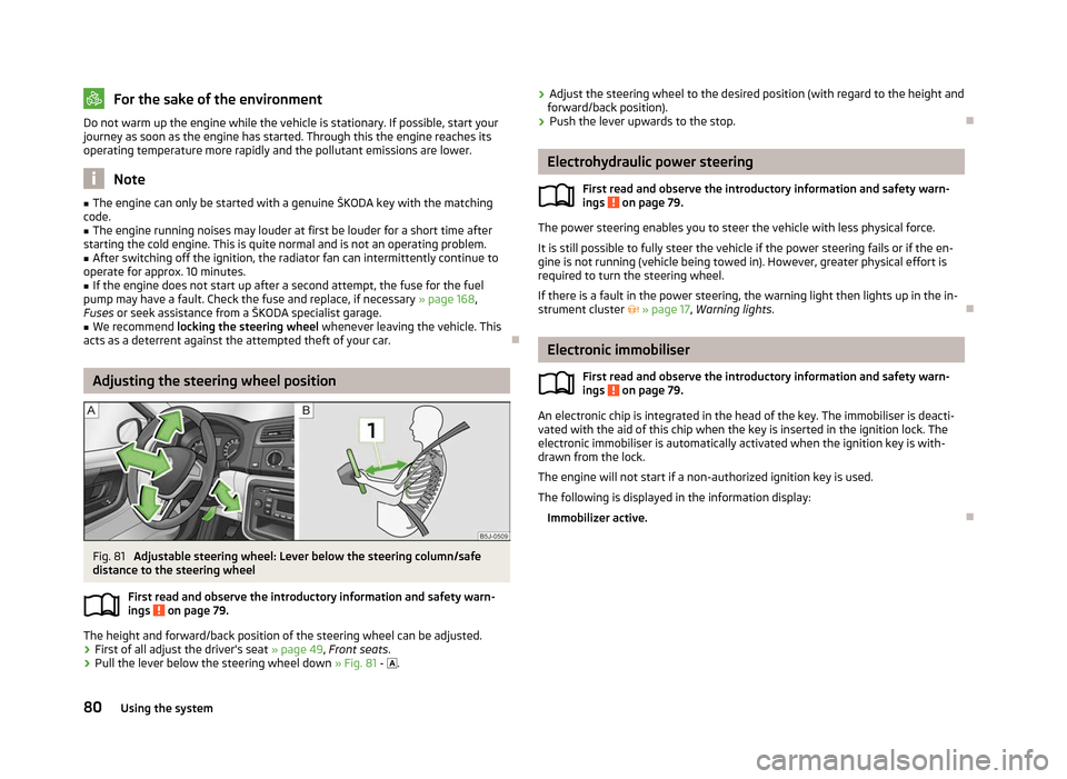
Fig. 81
Adjustable steering wheel: Lever below the steering column/safe
distance to the steering wheel
First read and observe the introductory information and safety warn-
ings on page 79.
The height and forward/back position of the steering wheel can be adjusted.
›
First of all adjust the driver's seat
» page 49, Front seats.
› Pull the lever below the steering wheel down
» Fig. 81 - .
ä ›
Adjust the steering wheel to the desired position (with regard to the height and
forward/back position).
› Push the lever upwards to the stop. Ð Electrohydraulic power steering
First read and observe the introductory information and safety warn-
ings on page 79.
The power steering enables you to steer the vehicle with less physical force.
It is still possible to fully steer the vehicle if the power steering fails or if the en-
gine is not running (vehicle being towed in). However, greater physical effort is
required to turn the steering wheel.
If there is a fault in the power steering, the warning light then lights up in the in-
strument cluster » page 17, Warning lights . Ð Electronic immobiliser
First read and observe the introductory information and safety warn-
ings on page 79.
An electronic chip is integrated in the head of the key. The immobiliser is deacti-
vated with the aid of this chip when the key is inserted in the ignition lock. The
electronic immobiliser is automatically activated when the ignition key is with-
drawn from the lock.
The engine will not start if a non-authorized ignition key is used.
The following is displayed in the information display: Immobilizer active. Ð
ä
ä
80 Using the system