ESP SKODA FABIA 2013 2.G / 5J User Guide
[x] Cancel search | Manufacturer: SKODA, Model Year: 2013, Model line: FABIA, Model: SKODA FABIA 2013 2.G / 5JPages: 223, PDF Size: 12.77 MB
Page 47 of 223
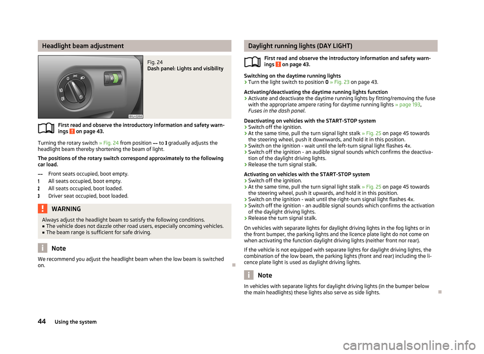
Headlight beam adjustmentFig. 24
Dash panel: Lights and visibility
First read and observe the introductory information and safety warn-
ings on page 43.
Turning the rotary switch » Fig. 24 from position
to
gradually adjusts the
headlight beam thereby shortening the beam of light.
The positions of the rotary switch correspond approximately to the following
car load.
Front seats occupied, boot empty.
All seats occupied, boot empty.
All seats occupied, boot loaded.
Driver seat occupied, boot loaded.
WARNINGAlways adjust the headlight beam to satisfy the following conditions.■The vehicle does not dazzle other road users, especially oncoming vehicles.■
The beam range is sufficient for safe driving.
Note
We recommend you adjust the headlight beam when the low beam is switched
on.
Daylight running lights (DAY LIGHT)
First read and observe the introductory information and safety warn-
ings
on page 43.
Switching on the daytime running lights
›
Turn the light switch to position 0 » Fig. 23 on page 43.
Activating/deactivating the daytime running lights function
›
Activate and deactivate the daytime running lights by fitting/removing the fuse
with the appropriate ampere rating for daytime running lights » page 193,
Fuses in the dash panel .
Deactivating on vehicles with the START-STOP system
›
Switch off the ignition.
›
At the same time, pull the turn signal light stalk » Fig. 25 on page 45 towards
the steering wheel, push it downwards, and hold it in this position.
›
Switch on the ignition - wait until the left-turn signal light flashes 4x.
›
Switch off the ignition - an audible signal sounds which confirms the deactiva- tion of the daylight driving lights.
›
Release the turn signal stalk.
Activating on vehicles with the START-STOP system
›
Switch off the ignition.
›
At the same time, pull the turn signal light stalk » Fig. 25 on page 45 towards
the steering wheel, push it upwards, and hold it in this position.
›
Switch on the ignition - wait until the right-turn signal light flashes 4x.
›
Switch off the ignition - an audible signal sounds which confirms the activation
of the daylight driving lights.
›
Release the turn signal stalk.
On vehicles with separate lights for daylight driving lights in the fog lights or in
the front bumper, the parking lights and the licence plate light do not come on
when activating the function daylight driving lights (neither front nor rear).
If the vehicle is not equipped with separate lights for daylight driving lights, the
combination of the low beam, the parking lights (front and rear) including the li-
cence plate light is used as daylight driving lights.
Note
In vehicles with separate lights for daylight driving lights (in the bumper below
the main headlights) these lights also serve as side lights.
44Using the system
Page 61 of 223
›Press the locking button in the direction of the arrow
» Fig. 42 - and pull the
head restraint out.›
To re-insert the head restraint, push it far enough down into the seat backrest until the locking button clicks into place.
Best protection is achieved if the top edge of the head restraint is at the same
level as the upper part of your head.
The head restraints must be adjusted to match the size of the seat occupant. Cor-rectly adjusted head restraints together with the seat belts offer effective protec-
tion for the occupants » page 125.
WARNING■
The head restraints must be correctly adjusted in order to offer effective
protection for the occupants in the event of an accident.■
Never drive with the head restraints removed - there is a risk of injury.
■
If the rear seats are occupied, the rear head restraint must not be in the
lower position.
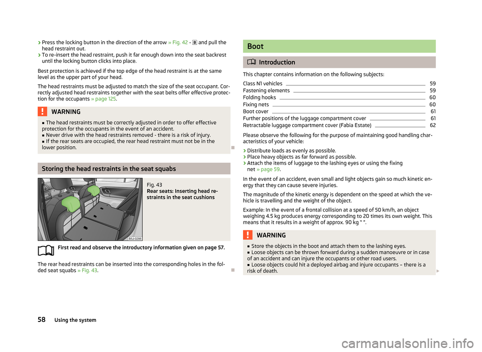
Storing the head restraints in the seat squabs
Fig. 43
Rear seats: Inserting head re-
straints in the seat cushions
First read and observe the introductory information given on page 57.
The rear head restraints can be inserted into the corresponding holes in the fol-
ded seat squabs » Fig. 43.
Boot
Introduction
This chapter contains information on the following subjects:
Class N1 vehicles
59
Fastening elements
59
Folding hooks
60
Fixing nets
60
Boot cover
61
Further positions of the luggage compartment cover
61
Retractable luggage compartment cover (Fabia Estate)
62
Please observe the following for the purpose of maintaining good handling char-
acteristics of your vehicle:
›
Distribute loads as evenly as possible.
›
Place heavy objects as far forward as possible.
›
Attach the items of luggage to the lashing eyes or using the fixing net » page 59 .
In the event of an accident, even small and light objects gain so much kinetic en-
ergy that they can cause severe injuries.
The magnitude of the kinetic energy is dependent on the speed at which the ve-
hicle is travelling and the weight of the object.
Example: In the event of a frontal collision at a speed of 50 km/h, an object
weighing 4.5 kg produces energy corresponding to 20 times its own weight. This
means that it results in a weight of approx. 90 kg “ ”.
WARNING■ Store the objects in the boot and attach them to the lashing eyes.■Loose objects can be thrown forward during a sudden manoeuvre or in case
of an accident and can injure the occupants or other road users.■
Loose objects could hit a deployed airbag and injure occupants – there is a
risk of death.
58Using the system
Page 83 of 223
We recommend that you leave the air outlet vents 3 » Fig. 77 on page 77 in the
open position in all operating modes.
Note
If the air distribution is directed only towards the windows, the total amount of
air is used to defrost the windows and thus no air will be fed to the footwell. This
can limit the heating comfort.
Recirculated air mode
First read and observe the introductory information given on page 78.
Recirculated air mode prevents polluted air from outside the vehicle getting into
the vehicle, for example when driving through a tunnel or when standing in a
traffic jam.
Switching on/off
›
Press the
button.
The indicator light in the button lights up.
›
Press the
button again.
The indicator light in the button goes out.
Recirculated air mode is switched off automatically if the air distribution control
C
» Fig. 78 on page 79 is turned to the
position. Recirculated air mode can be
switched on again from this setting by pressing the
button again.
WARNINGNever leave recirculated air mode on over a longer period, as “stale air” can
cause fatigue in the driver and the passengers, reduce attention levels and al-
so cause the windows to mist up. The risk of having an accident increases.
Switch off recirculated air mode as soon as the windows start to mist up.
Air conditioning system (manual air conditioning
system)
Introduction
This chapter contains information on the following subjects: Operation
81
Setting the air conditioning system
82
Recirculated air mode
82
The cooling system operates only if the following conditions are met. The cooling system is switched on » page 81.
The engine is running.
The outside temperature is above approximately +2 °C.
The blower switch is switched on (positions 1-4).
If the desired interior temperature can also be achieved without activating the cooling system, fresh air mode should be selected.
If the coolant temperature is too high, the cooling system is switched off to en-
sure that the engine cools down.
CAUTION
■ Under certain circumstances, air at a temperature of about 5 °C can flow out of
the vents when the cooling system is switched on.■
Lengthy and uneven distribution of the air flow out of the vents (especially
around the feet) and large differences in temperature, for example, when getting
out of the vehicle, can cause susceptible individuals to catch a cold.
Note
We recommend that you have the air conditioning system cleaned by a specialist
garage once every year.80Using the system
Page 87 of 223
Air flow to the windows
Air flow to the upper body
Air flow in the footwell
Recirculating air operation on/off » page 84
Switch cooling system on/off
Note
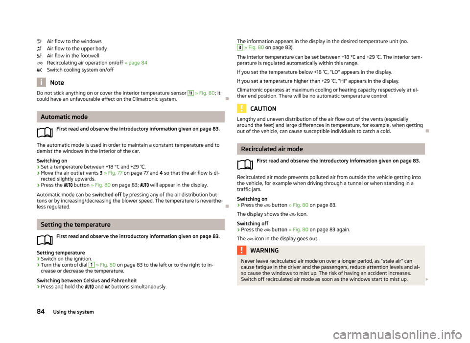
Do not stick anything on or cover the interior temperature sensor 11 » Fig. 80 ; it
could have an unfavourable effect on the Climatronic system.
Automatic mode
First read and observe the introductory information given on page 83.
The automatic mode is used in order to maintain a constant temperature and to
demist the windows in the interior of the car.
Switching on
›
Set a temperature between +18 °C and +29 ℃.
›
Move the air outlet vents 3 » Fig. 77 on page 77 and 4 so that the air flow is di-
rected slightly upwards.
›
Press the
button » Fig. 80 on page 83;
will appear in the display.
Automatic mode can be switched off by pressing any of the air distribution but-
tons or by increasing/decreasing the blower speed. The temperature is neverthe-
less regulated.
Setting the temperature
First read and observe the introductory information given on page 83.
Setting temperature
›
Switch on the ignition.
›
Turn the control dial
1
» Fig. 80 on page 83 to the left or to the right to in-
crease or decrease the temperature.
Switching between Celsius and Fahrenheit
›
Press and hold the
and
buttons simultaneously.
The information appears in the display in the desired temperature unit (no.3
» Fig. 80 on page 83).
The interior temperature can be set between +18 °C and +29 ℃. The interior tem-
perature is regulated automatically within this range.
If you set the temperature below +18 ℃, “LO” appears in the display.
If you set a temperature higher than +29 ℃, “HI” appears in the display.
Climatronic operates at maximum cooling or heating capacity respectively at ei- ther end position. There will be no automatic temperature control.
CAUTION
Lengthy and uneven distribution of the air flow out of the vents (especially
around the feet) and large differences in temperature, for example, when getting
out of the vehicle, can cause susceptible individuals to catch a cold.
Recirculated air mode
First read and observe the introductory information given on page 83.
Recirculated air mode prevents polluted air from outside the vehicle getting intothe vehicle, for example when driving through a tunnel or when standing in a
traffic jam.
Switching on
›
Press the
button » Fig. 80 on page 83.
The display shows the
icon.
Switching off
›
Press the
button » Fig. 80 on page 83 again.
The
icon in the display goes out.
WARNINGNever leave recirculated air mode on over a longer period, as “stale air” can
cause fatigue in the driver and the passengers, reduce attention levels and al-
so cause the windows to mist up. The risk of having an accident increases.
Switch off recirculated air mode as soon as the windows start to mist up. 84Using the system
Page 88 of 223
NoteIf recirculated air mode is switched on for around 15 minutes, the symbol will
begin to flash in the display as a sign that the recirculated air mode is switched on long-term. If the recirculated air mode is not switched off, the symbol flashes for
around 5 minutes.
Controlling the blower
First read and observe the introductory information given on page 83.
The Climatronic system controls the blower stages automatically in line with the
interior temperature. However, the blower level can be manually adjusted to suit your particular needs.
›
Turn control dial
10
» Fig. 80 on page 83 to the left or to the right to increase or
decrease the blower speed.
If the blower is switched off, the Climatronic system is switched off.
The blower speed set is indicated by displaying the corresponding number of seg- ments in icon
9
» Fig. 80 on page 83 in the display.
WARNING■
“Stale air” may result in fatigue in the driver and occupants, reduce attention
levels and also cause the windows to mist up. The risk of having an accident
increases.■
Do not switch off the Climatronic system for longer than necessary.
■
Switch on the Climatronic system as soon as the windows mist up.
Defrosting windscreen
First read and observe the introductory information given on page 83.
Switching on
›
Press the
button » Fig. 80 on page 83.
Switching off
›
Press the
button » Fig. 80 on page 83 again or press the
button.
More air flows out of the air outlet vents 1 and 2 » Fig. 77 on page 77. The temper-
ature control is controlled automatically.
85Heating and air conditioning
Page 96 of 223
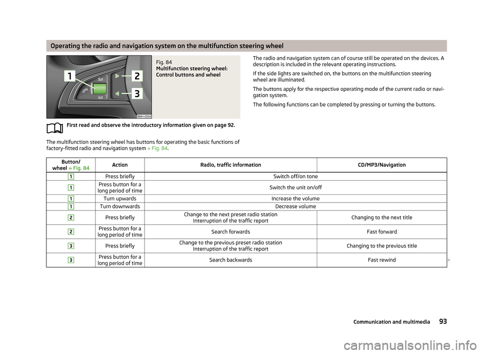
Operating the radio and navigation system on the multifunction steering wheelFig. 84
Multifunction steering wheel:
Control buttons and wheel
First read and observe the introductory information given on page 92.
The multifunction steering wheel has buttons for operating the basic functions of factory-fitted radio and navigation system » Fig. 84.
The radio and navigation system can of course still be operated on the devices. A
description is included in the relevant operating instructions.
If the side lights are switched on, the buttons on the multifunction steering
wheel are illuminated.
The buttons apply for the respective operating mode of the current radio or navi- gation system.
The following functions can be completed by pressing or turning the buttons.Button/
wheel » Fig. 84ActionRadio, traffic informationCD/MP3/Navigation1Press brieflySwitch off/on tone1Press button for a
long period of timeSwitch the unit on/off1Turn upwardsIncrease the volume1Turn downwardsDecrease volume2Press brieflyChange to the next preset radio station Interruption of the traffic reportChanging to the next title2Press button for a
long period of timeSearch forwardsFast forward3Press brieflyChange to the previous preset radio station Interruption of the traffic reportChanging to the previous title3Press button for a
long period of timeSearch backwardsFast rewind 93Communication and multimedia
Page 103 of 223
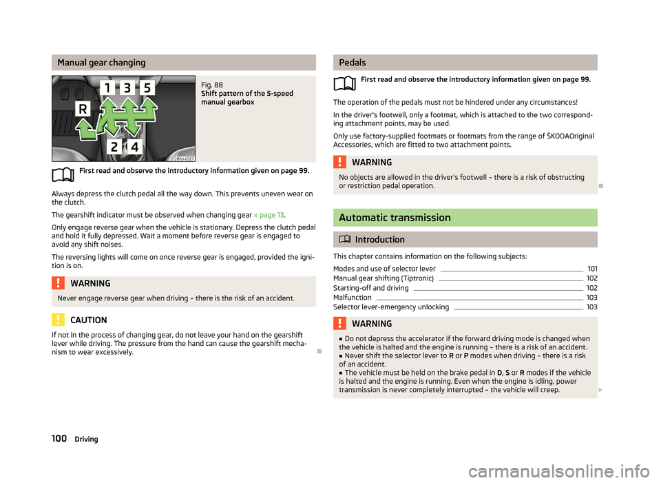
Manual gear changingFig. 88
Shift pattern of the 5-speed
manual gearbox
First read and observe the introductory information given on page 99.
Always depress the clutch pedal all the way down. This prevents uneven wear on the clutch.
The gearshift indicator must be observed when changing gear » page 13.
Only engage reverse gear when the vehicle is stationary. Depress the clutch pedal
and hold it fully depressed. Wait a moment before reverse gear is engaged to
avoid any shift noises.
The reversing lights will come on once reverse gear is engaged, provided the igni- tion is on.
WARNINGNever engage reverse gear when driving – there is the risk of an accident.
CAUTION
If not in the process of changing gear, do not leave your hand on the gearshiftlever while driving. The pressure from the hand can cause the gearshift mecha-
nism to wear excessively.
Pedals
First read and observe the introductory information given on page 99.
The operation of the pedals must not be hindered under any circumstances!
In the driver's footwell, only a footmat, which is attached to the two correspond- ing attachment points, may be used.
Only use factory-supplied footmats or footmats from the range of ŠKODAOriginal Accessories, which are fitted to two attachment points.
WARNINGNo objects are allowed in the driver's footwell – there is a risk of obstructing
or restriction pedal operation.
Automatic transmission
Introduction
This chapter contains information on the following subjects:
Modes and use of selector lever
101
Manual gear shifting (Tiptronic)
102
Starting-off and driving
102
Malfunction
103
Selector lever-emergency unlocking
103WARNING■ Do not depress the accelerator if the forward driving mode is changed when
the vehicle is halted and the engine is running – there is a risk of an accident.■
Never shift the selector lever to R or P modes when driving – there is a risk
of an accident.
■
The vehicle must be held on the brake pedal in D, S or R modes if the vehicle
is halted and the engine is running. Even when the engine is idling, power
transmission is never completely interrupted – the vehicle will creep.
100Driving
Page 107 of 223
New engineFirst read and observe the introductory information given on page 103.
The engine has to be run in during the first 1 500 kilometres.Up to 1 000 kilometres
›
Do not drive faster than 3/4 of the maximum speed of the gear in use, i.e. 3/4 of
the maximum permissible engine speed.
›
No full throttle.
›
Avoid high engine speeds.
›
Do not tow a trailer.
From 1 000 up to 1 500 kilometres
Gradually increase the power output of the engine up to the full speed of the
gear engaged, i.e. up to the maximum permissible engine speed.
The red scale on the rev counter indicates the range in which the system beginsto limit the engine speed.
During the first operating hours the engine has higher internal friction than later until all of the moving parts have harmonized. The driving style which you adopt
during the first approx.1 500 kilometres plays a decisive part in the success of
running in your car.
Never drive at unnecessarily high engine speeds even after the running-in period. On vehicles fitted with a manual gearbox, at the very latest shift up into the next
gear when the red area is reached. Observe the recommended gear » page 13,
Recommended gear . Very high engine speeds when accelerating (accelerator) are
automatically restricted »
.
In vehicles with manual transmission, do not drive at unnecessarily low engine
speeds. Shift down a gear when the engine is no longer running smoothly. Ob-
serve the recommended gear » page 13, Recommended gear .
CAUTION
■
The engine is not protected from excessive engine revs caused by shifting
down at the wrong time. This can result in a sudden increase in revs beyond the
permissible maximum rpm and hence engine damage.■
Never rev up a cold engine when the vehicle is stationary or when driving in in-
dividual gears.
For the sake of the environmentDo not drive at unnecessarily high engine speeds. Shifting up sooner helps save
fuel, reduces engine noise and protects the environment.
New tyres
First read and observe the introductory information given on page 103.
New tyres have to be “run in” since they do not offer optimal grip at first. Drive
especially carefully for the first 500 km or so.
New brake pads
First read and observe the introductory information given on page 103.
New brake pads initially do not provide optimal braking performance. They firstneed to be “run in”. Drive especially carefully for the first 200 km or so.
Economical driving and respect the environment
Introduction
This chapter contains information on the following subjects:
Driving with anticipation
105
Economical gear changing.
105
Avoiding full throttle
106
Reducing idling
106
Avoiding short distances
106
Checking tyre pressure
106
Avoiding unnecessary ballast
107
Regular maintenance
107
Saving electrical energy
107
Environmental compatibility
107
104Driving
Page 116 of 223
XDL function (Fabia RS and Fabia Estate RS only)
XDL is an extension to the electronic differential lock. XDL does not respond to
traction, but to the relief of the inner front wheel during fast cornering. The active
brake intervention on the brake of the inner wheel prevents it from spinning.
Thus, the traction is improved and the vehicle continues to follow the desired
track.
Parking aid
Introduction
This chapter contains information on the following subjects:
Function
113
Activation/deactivation
114WARNING■ The parking aid is not a substitute for the driver paying proper attention and
it is always the driver's responsibility to take care when reversing the vehicle
or carrying out similar manoeuvres. Pay particular attention to small children
and animals as they are not recognised by the parking aid sensors.■
Before reversing, you should make sure that there are no small obstacles,
such as rocks, thin posts, trailer drawbars etc. behind your vehicle. Such ob-
stacles may not be recognised by the parking aid sensors.
■
Under certain circumstances, surfaces of certain objects and types of cloth-
ing cannot reflect the system signals. Thus, these objects or people who wear
such clothing are not recognised by the System sensors.
■
External sound sources can have a detrimental effect on the system. Under
adverse conditions, this may cause objects or people to not be recognised by the system.
CAUTION
■ If a warning signal sounds for about 3 seconds after activating the system and
there is no obstacle close to your car, this indicates a system fault. Have the fault
rectified by a specialist garage.■
The sensors must be kept clean (free of ice, etc.) to enable the parking aid to
operate properly.
■ Under adverse weather conditions (heavy rain, water vapour, very low or high
temperatures etc.) system function may be limited.■
Additionally fitted modules, such as a bicycle rack, can impair the function of the
parking aid.
Function
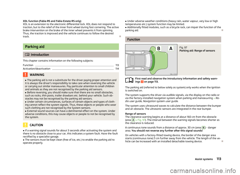
Fig. 97
Parking aid: Range of sensors
First read and observe the introductory information and safety warn- ings on page 113.
The parking aid (referred to below solely as system) only works when the ignition
is switched on.
The system supports the driver via audible signals, via the display on the radio or
via the factory-installed navigation system when parking and manoeuvring » Ra-
dio user guide, Navigation system user guide.
The system uses ultrasound waves to calculate the distance between the bumper
and an obstacle. The ultrasonic sensors are integrated in the rear bumper.
Range of sensors
The clearance warning begins at a distance of about 160 cm from the obstacle
(area
A
» Fig. 97 ). The interval between the warning signals becomes shorter as
the clearance is reduced.
A continuous tone sounds from a distance of approx. 30 cm (area
B
) - danger
area. You should not reverse any further after this signal sounds!
On vehicles with a factory-fitted towing device, the border of the danger area starts (continuous tone) 5 cm further away from the vehicle. The length of the ve-
hicle can be increased with an installed detachable towing device.
113Assist systems
Page 128 of 223
What influences driving safety?First read and observe the introductory information and safety warn-
ings
on page 124.
The driver is fully responsible for himself and his occupants. If your driving safety is effected, you place yourself and the oncoming traffic at risk.
The following guidelines must therefore be observed. › Do not get distracted from concentrating on the traffic situation, e.g. by your
passengers or mobile phone calls.
› Never drive when your driving ability is impaired, e.g. through medication, alco-
hol or drugs.
› Keep to the traffic regulations and the permissible speed limit.
› Always adjust the driving speed to the road, traffic and weather conditions.
› Take regular breaks on long journeys – at least every two hours.
Correct seated position
Introduction
This chapter contains information on the following subjects:
Correct seated position of the driver
126
Correct seated position of the front passenger
126
Correct seated position of the rear seat passengers
126
Examples of incorrect seated positions
126WARNINGGeneral information■The front seats and head restraints must be adjusted to match the body
size at all times and the seat belt must always be fastened properly to provide the most effective levels of protection to the passengers.■
If the occupant adopts an incorrect seated position, he is exposed to life-
threatening injuries, in case he is hit by a deployed airbag.
■
If the occupants on the rear seats are not sitting upright, the risk of injury is
increased due to incorrect routing of the seat belt.
■
The seat backrests must not be reclined too far when driving otherwise this
will affect proper operation of the seat belts and of the airbag system – risk of
injury.
WARNINGInformation for the driver■Always assume the correct seated position before setting off and do not
change this position while driving. Also advise your passengers to adopt the
correct seated position and not to change this position while the car is mov-
ing.■
Keep a distance of at least 25 cm from the steering wheel. Not keeping to
this minimum distance will mean that the airbag system will not be able to
properly protect you – risk of death.
■
When driving, hold the steering wheel with both hands firmly on the outer
edge in the 9 o'clock and 3 o'clock position. Never hold the steering wheel in
the 12 o'clock position or in any other way (e.g. in the middle or inner edge of
the steering wheel). In such cases, you could severely injure your arms, hands
and head when the driver airbag is deployed.
■
Ensure that there are no objects in the driver's footwell as they may get
caught behind the pedals while you are driving or under braking. You would
then no longer be able to operate the clutch, brake or accelerate.
WARNINGInformation for the front seat passenger■Maintain a distance of at least 25 cm from the dash panel. Not maintaining
this minimum distance will mean that the airbag system will not be able to
properly protect you - there is a risk that you could be killed.■
Always keep your feet in the footwell when the car is being driven - never
place your feet on the instrument panel, out of the window or on the seats.
You will be exposed to increased risk of injury if it becomes necessary to apply
the brakes or in the event of an accident. You may suffer fatal injuries when
an airbag is deployed if you have adopted an incorrect seating position.
125Passive Safety