parking brake SKODA FABIA 2013 2.G / 5J Owner's Manual
[x] Cancel search | Manufacturer: SKODA, Model Year: 2013, Model line: FABIA, Model: SKODA FABIA 2013 2.G / 5JPages: 223, PDF Size: 12.77 MB
Page 6 of 223
Table of Contents
Materials defect liability and ŠKODA warranty for
new cars5
Mobility warranty and ŠKODA extended
warranty
6
Abbreviations
Using the system
Cockpit
9
Overview
8
Instruments and Indicator Lights
10
Instrument cluster
10
Multifunction display (MFD)
13
Service Interval Display
16
MAXI DOT display
18
Warning lights
20
Unlocking and locking
28
Unlocking and locking
28
Central locking system
31
Remote control
34
Anti-theft alarm system
35
Tailgate
37
Electrical power windows
38
Electric sliding/tilting roof
40
Lights and visibility
43
Lights
43
Interior lights
48
Visibility
49
Windscreen wipers and washers
50
Rear window
53Seats and storage54Front seats54
Rear seats
56
Head restraints
57
Boot
58
Variable loading floor in the luggage
compartment (Fabia Estate)
62
Net partition (Fabia Estate)
64
Bicycle carrier in the luggage compartment
65
Roof rack system
67
Useful equipment
69
Storage compartments
72
Heating and air conditioning
77
Heating, ventilation, cooling
77
Heating
78
Air conditioning system (manual air conditioning
system)
80
Climatronic (automatic air conditioningsystem)
83
Communication and multimedia
86
Universal telephone preinstallation GSM II
86
Voice control
91
Multimedia
92
Driving
Starting-off and Driving
95
Steering
95
Starting and stopping the engine
96
Brakes
98
Manual gear shifting and pedals
99
Automatic transmission
100
Running in
103
Economical driving and respect the
environment
104
Avoiding damage to your vehicle
108
Driving abroad
109Assist systems111Brake assist systems111
Parking aid
113
Cruise control system
114
START-STOP
116
Towing a trailer
118
Towing device
118
Trailer
121
Safety
Passive Safety
124
General information
124
Correct seated position
125
Seat belts
128
Wearing seat belts
128
Inertia reel and belt pretensioners
131
Airbag system
133
Description of the airbag system
133
Airbag overview
134
Deactivating airbags
137
Transporting children safely
140
Child seat
140
Fastening systems
143
General Maintenance
Car care
145
Service intervals
145
Services, modifications and technical
alterations
147
Washing the car
150
Vehicle exterior care
151
Care of the interior
1553Table of Contents
Page 12 of 223
Using the system
Cockpit
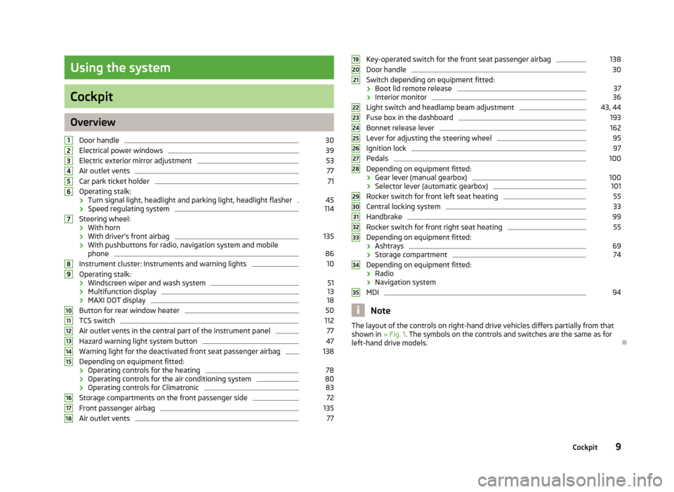
OverviewDoor handle
30
Electrical power windows
39
Electric exterior mirror adjustment
53
Air outlet vents
77
Car park ticket holder
71
Operating stalk:
› Turn signal light, headlight and parking light, headlight flasher
45
›
Speed regulating system
114
Steering wheel:
› With horn
› With driver’s front airbag
135
›With pushbuttons for radio, navigation system and mobile
phone
86
Instrument cluster: Instruments and warning lights
10
Operating stalk:
› Windscreen wiper and wash system
51
›Multifunction display
13
›
MAXI DOT display
18
Button for rear window heater
50
TCS switch
112
Air outlet vents in the central part of the instrument panel
77
Hazard warning light system button
47
Warning light for the deactivated front seat passenger airbag
138
Depending on equipment fitted:
› Operating controls for the heating
78
›Operating controls for the air conditioning system
80
›Operating controls for Climatronic
83
Storage compartments on the front passenger side
72
Front passenger airbag
135
Air outlet vents
77123456789101112131415161718Key-operated switch for the front seat passenger airbag138Door handle30
Switch depending on equipment fitted:
› Boot lid remote release
37
›Interior monitor
36
Light switch and headlamp beam adjustment
43, 44
Fuse box in the dashboard
193
Bonnet release lever
162
Lever for adjusting the steering wheel
95
Ignition lock
97
Pedals
100
Depending on equipment fitted:
› Gear lever (manual gearbox)
100
›Selector lever (automatic gearbox)
101
Rocker switch for front left seat heating
55
Central locking system
33
Handbrake
99
Rocker switch for front right seat heating
55
Depending on equipment fitted:
› Ashtrays
69
›Storage compartment
74
Depending on equipment fitted:
› Radio
› Navigation system
MDI
94
Note
The layout of the controls on right-hand drive vehicles differs partially from that
shown in » Fig. 1. The symbols on the controls and switches are the same as for
left-hand drive models.19202122232425262728293031323334359Cockpit
Page 23 of 223
Note■Warning messages shown in the MAXI DOT display must be confirmed with but-
ton B » Fig. 7 on page 18 to call up the main menu.■
As long as the operational faults are not rectified, the symbols are always indi-
cated again. After they are displayed for the first time, the symbols continue to be
indicated without any extra messages for the driver.
Warning lights
Introduction
This chapter contains information on the following subjects:
Handbrake
20
Brake system
20
Seat belt warning light
21
Alternator
21
Door open
21
Engine oil
21
Coolant
22
Power steering
23
Electronic Stability Control (ESC)
23
Traction Control System (ASR)
23
Antilock brake system (ABS)
24
The rear fog light
24
Bulb failure
24
Exhaust inspection system
24
Glow plug system (diesel engine)
24
ECU fault light (petrol engine)
25
Diesel particulate filter (diesel engine)
25
Fuel reserve
25
Airbag system
26
Tyre pressure
26
Windscreen washer fluid level
26
Traction control (TCS) switched off
26
Turn signal system
26
Low beam
27 Fog lights27 Cruise control system27
Selector lever lock
27
Main beam
27
The warning lights show certain functions/faults and may be accompanied by au-
dible signals.
WARNING■ If illuminated warning lights and the corresponding descriptions and warn-
ing notes are not observed, this may result in severe injuries or major vehicle
damage.■
The engine compartment of your car is a hazardous area. There is a risk of
injuries, scalding, accidents and fire when working in the engine compart-
ment, e.g. inspecting and replenishing oil and other fluids. It is essential to ob-
serve safety notes » page 160, Engine compartment .
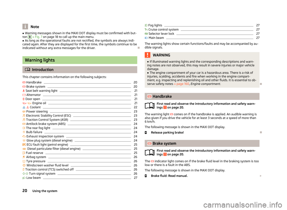
Handbrake
First read and observe the introductory information and safety warn-
ings
on page 20.
The warning light
comes on if the handbrake is applied. An audible warning is
also given if you drive the vehicle for at least 3 seconds at a speed of more than
6 km/h.
The following message is shown in the MAXI DOT display.
Release parking brake!
Brake system
First read and observe the introductory information and safety warn-
ings
on page 20.
The
indicator light comes on if the brake fluid level in the braking system is too
low or there is a fault in the ABS.
The following message is shown in the MAXI DOT display. Brake fluid: Read manual.
20Using the system
Page 27 of 223
Antilock brake system (ABS)First read and observe the introductory information and safety warn-
ings
on page 20.
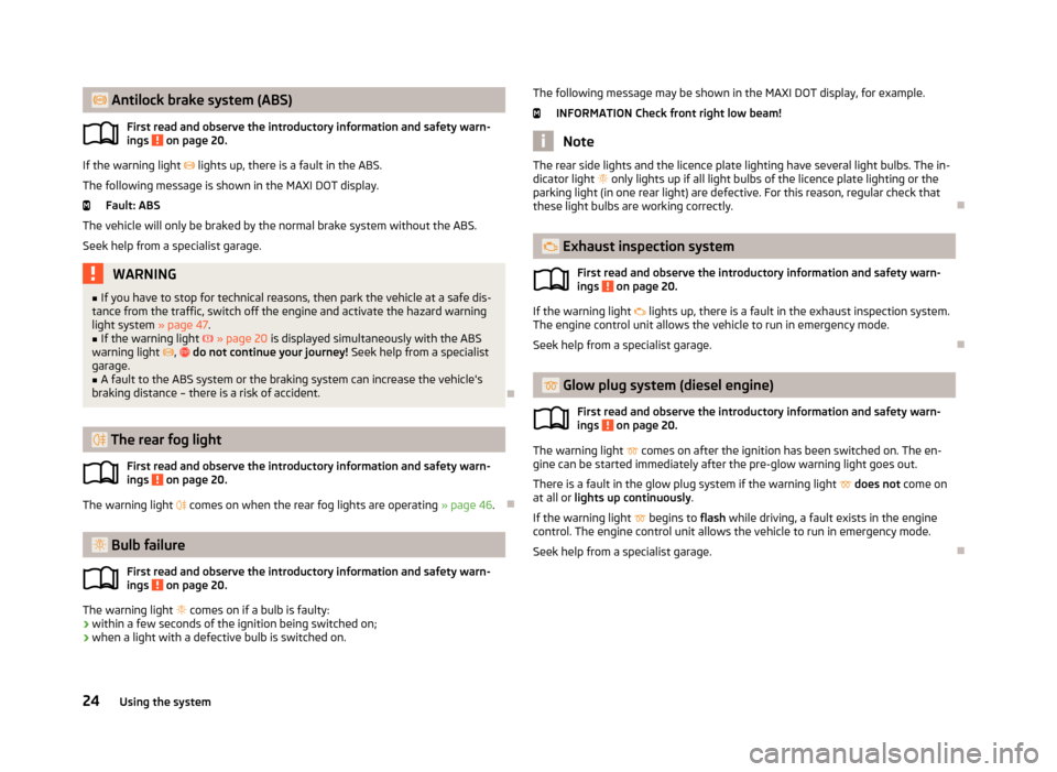
If the warning light lights up, there is a fault in the ABS.
The following message is shown in the MAXI DOT display. Fault: ABS
The vehicle will only be braked by the normal brake system without the ABS.
Seek help from a specialist garage.
WARNING■ If you have to stop for technical reasons, then park the vehicle at a safe dis-
tance from the traffic, switch off the engine and activate the hazard warning
light system » page 47.■
If the warning light » page 20 is displayed simultaneously with the ABS
warning light , do not continue your journey! Seek help from a specialist
garage.
■
A fault to the ABS system or the braking system can increase the vehicle's
braking distance – there is a risk of accident.
The rear fog light
First read and observe the introductory information and safety warn-ings
on page 20.
The warning light
comes on when the rear fog lights are operating » page 46.
Bulb failure
First read and observe the introductory information and safety warn-ings
on page 20.
The warning light
comes on if a bulb is faulty:
› within a few seconds of the ignition being switched on;
› when a light with a defective bulb is switched on.
The following message may be shown in the MAXI DOT display, for example.
INFORMATION Check front right low beam!
Note
The rear side lights and the licence plate lighting have several light bulbs. The in-
dicator light only lights up if all light bulbs of the licence plate lighting or the
parking light (in one rear light) are defective. For this reason, regular check that
these light bulbs are working correctly.
Exhaust inspection system
First read and observe the introductory information and safety warn-
ings
on page 20.
If the warning light
lights up, there is a fault in the exhaust inspection system.
The engine control unit allows the vehicle to run in emergency mode.
Seek help from a specialist garage.
Glow plug system (diesel engine)
First read and observe the introductory information and safety warn-ings
on page 20.
The warning light
comes on after the ignition has been switched on. The en-
gine can be started immediately after the pre-glow warning light goes out.
There is a fault in the glow plug system if the warning light
does not come on
at all or lights up continuously .
If the warning light
begins to flash while driving, a fault exists in the engine
control. The engine control unit allows the vehicle to run in emergency mode.
Seek help from a specialist garage.
24Using the system
Page 104 of 223
CAUTION■If the selector lever is shifted to N while the vehicle is being driven you must lift
off the accelerator pedal and you will need to wait until the engine has reached
its idling speed before shifting the selector lever to a forward driving mode again.■
At temperatures below -10 °C, the engine can only be started in selector lever
position P.
■
Never try to hold the vehicle using the accelerator pedal when stopping on a hill
– this may lead to transmission damage.
Note
The ignition key can only be withdrawn once the ignition has been switched off if
the selector lever is in the P position 1)
.
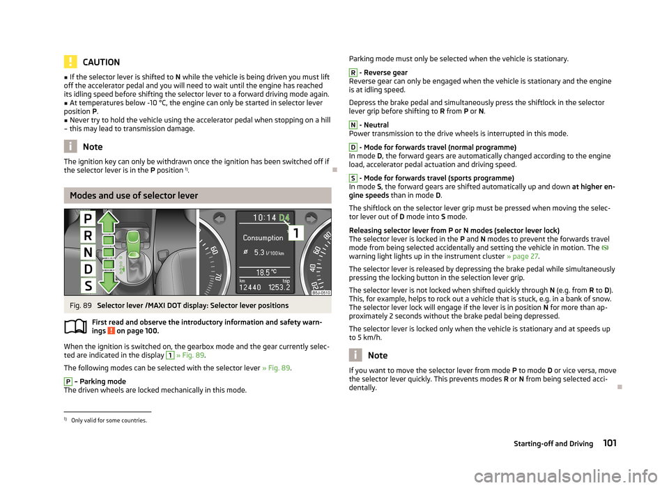
Modes and use of selector lever
Fig. 89
Selector lever /MAXI DOT display: Selector lever positions
First read and observe the introductory information and safety warn-
ings
on page 100.
When the ignition is switched on, the gearbox mode and the gear currently selec-
ted are indicated in the display
1
» Fig. 89 .
The following modes can be selected with the selector lever » Fig. 89.
P
– Parking mode
The driven wheels are locked mechanically in this mode.
Parking mode must only be selected when the vehicle is stationary.R
- Reverse gear
Reverse gear can only be engaged when the vehicle is stationary and the engine
is at idling speed.
Depress the brake pedal and simultaneously press the shiftlock in the selector
lever grip before shifting to R from P or N.
N
- Neutral
Power transmission to the drive wheels is interrupted in this mode.
D
- Mode for forwards travel (normal programme)
In mode D, the forward gears are automatically changed according to the engine
load, accelerator pedal actuation and driving speed.
S
- Mode for forwards travel (sports programme)
In mode S, the forward gears are shifted automatically up and down at higher en-
gine speeds than in mode D.
The shiftlock on the selector lever grip must be pressed when moving the selec-
tor lever out of D mode into S mode.
Releasing selector lever from P or N modes (selector lever lock) The selector lever is locked in the P and N modes to prevent the forwards travel
mode from being selected accidentally and setting the vehicle in motion. The
warning light lights up in the instrument cluster » page 27.
The selector lever is released by depressing the brake pedal while simultaneously
pressing the locking button in the selection lever grip.
The selector lever is not locked when shifted quickly through N (e.g. from R to D).
This, for example, helps to rock out a vehicle that is stuck, e.g. in a bank of snow.
The selector lever lock will engage if the lever is in position N for more than ap-
proximately 2 seconds without the brake pedal being depressed.
The selector lever is locked only when the vehicle is stationary and at speeds up to 5 km/h.
Note
If you want to move the selector lever from mode P
to mode D or vice versa, move
the selector lever quickly. This prevents modes R or N from being selected acci-
dentally.1)
Only valid for some countries.
101Starting-off and Driving
Page 105 of 223
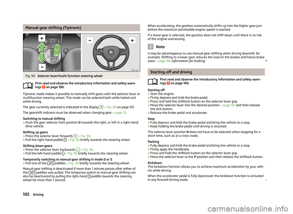
Manual gear shifting (Tiptronic)Fig. 90
Selector lever/multi-function steering wheel
First read and observe the introductory information and safety warn- ings
on page 100.
Tiptronic mode makes it possible to manually shift gears with the selector lever or
multifunction steering wheel. This mode can be selected both while halted and
while driving.
The gear currently selected is indicated in the display
1
» Fig. 89 on page 101.
The gearshift indicator must be observed when changing gear » page 13.
Switching to manual shifting
›
Push the gear selector from position D towards the right, or left in a right-hand
drive vehicle.
Shifting up gears
›
Press the selector lever forwards
+
» Fig. 90 .
›
Pull the right-hand paddle +
» Fig. 90 briefly towards the steering wheel.
Shifting down gears
›
Press the selector lever backwards
-
» Fig. 90 .
›
Pull the left-hand paddle -
» Fig. 90 briefly towards the steering wheel.
Temporarily switching to manual gear shifting in mode D or S
›
Pull one of the -/+ paddles
» Fig. 90 briefly towards the steering wheel .
Manual gear shifting is deactivated if more than 1 minute passes after either of
the -
/+ paddles was pulled. The temporary switch to manual gear shifting can
also be deactivated by pulling the right-hand + paddle towards the steering
wheel for more than 1 second.
When accelerating, the gearbox automatically shifts up into the higher gear just
before the maximum permissible engine speed is reached.
If a lower gear is selected, the gearbox does not shift down until there is no riskof the engine overrevving.
Note
It may be advantageous to use manual gear shifting when driving downhill, for
example. Shifting to a lower gear reduces the load on the brakes and hence brake wear » page 98 , Information for braking .
Starting-off and driving
First read and observe the introductory information and safety warn-
ings
on page 100.
Starting off
›
Start the engine.
›
Firmly depress and hold the brake pedal.
›
Press and hold the shiftlock button on the selector lever grip.
›
Move the selector lever into the desired position » page 101 and then release
the lock button.
›
Release the brake pedal and accelerate.
Stop
›
Fully depress and hold the brake pedal and bring the vehicle to a stop.
›
Keep holding the brake pedal until driving is resumed.
The selector lever position N does not have to be selected when stopping for a
short time, such as at a cross roads.
Parking
›
Fully depress and hold the brake pedal and bring the vehicle to a stop.
›
Firmly apply the handbrake.
›
Press and hold the shiftlock button on the selector lever grip.
›
Move the selector lever to the P position and then release the shiftlock button.
Kickdown
The kickdown function allows you to achieve maximum acceleration by your vehi-
cle while driving.
When the accelerator pedal is fully depressed, the kickdown function is activated
in any forward driving mode.
102Driving
Page 116 of 223
XDL function (Fabia RS and Fabia Estate RS only)
XDL is an extension to the electronic differential lock. XDL does not respond to
traction, but to the relief of the inner front wheel during fast cornering. The active
brake intervention on the brake of the inner wheel prevents it from spinning.
Thus, the traction is improved and the vehicle continues to follow the desired
track.
Parking aid
Introduction
This chapter contains information on the following subjects:
Function
113
Activation/deactivation
114WARNING■ The parking aid is not a substitute for the driver paying proper attention and
it is always the driver's responsibility to take care when reversing the vehicle
or carrying out similar manoeuvres. Pay particular attention to small children
and animals as they are not recognised by the parking aid sensors.■
Before reversing, you should make sure that there are no small obstacles,
such as rocks, thin posts, trailer drawbars etc. behind your vehicle. Such ob-
stacles may not be recognised by the parking aid sensors.
■
Under certain circumstances, surfaces of certain objects and types of cloth-
ing cannot reflect the system signals. Thus, these objects or people who wear
such clothing are not recognised by the System sensors.
■
External sound sources can have a detrimental effect on the system. Under
adverse conditions, this may cause objects or people to not be recognised by the system.
CAUTION
■ If a warning signal sounds for about 3 seconds after activating the system and
there is no obstacle close to your car, this indicates a system fault. Have the fault
rectified by a specialist garage.■
The sensors must be kept clean (free of ice, etc.) to enable the parking aid to
operate properly.
■ Under adverse weather conditions (heavy rain, water vapour, very low or high
temperatures etc.) system function may be limited.■
Additionally fitted modules, such as a bicycle rack, can impair the function of the
parking aid.
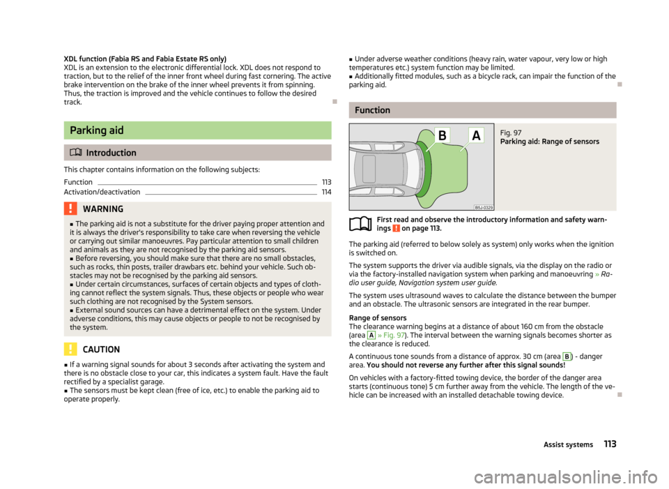
Function
Fig. 97
Parking aid: Range of sensors
First read and observe the introductory information and safety warn- ings on page 113.
The parking aid (referred to below solely as system) only works when the ignition
is switched on.
The system supports the driver via audible signals, via the display on the radio or
via the factory-installed navigation system when parking and manoeuvring » Ra-
dio user guide, Navigation system user guide.
The system uses ultrasound waves to calculate the distance between the bumper
and an obstacle. The ultrasonic sensors are integrated in the rear bumper.
Range of sensors
The clearance warning begins at a distance of about 160 cm from the obstacle
(area
A
» Fig. 97 ). The interval between the warning signals becomes shorter as
the clearance is reduced.
A continuous tone sounds from a distance of approx. 30 cm (area
B
) - danger
area. You should not reverse any further after this signal sounds!
On vehicles with a factory-fitted towing device, the border of the danger area starts (continuous tone) 5 cm further away from the vehicle. The length of the ve-
hicle can be increased with an installed detachable towing device.
113Assist systems
Page 120 of 223
›The engine has not yet reached the minimum temperature for the START STOP
mode.
› The temperature inside the vehicle has not reached the desired temperature
set in the air-conditioning system/heating.
› The external temperature is very low/high.
› Intensive windscreen deicing (Climatronic) or windscreen deicing/ventilation is
switched on at the maximum air temperature setting (manual air conditioning
system).
› The parking aid is activated.
› The charge state of the vehicle battery is too low.
› The stationary vehicle is on a steep hill or a steep slope.
› The idling speed is too high.
› The steering angle is too great (manoeuvring).
The
warning symbol appears in the instrument cluster display.
The automatic start procedure runs again During the STOP phase, the engine fires up without any active driver intervention,
e.g. in the following situations.
› The vehicle has begun to roll, e.g. on a slope.
› The difference between the temperature setting of the air-conditioning sys-
tem/heating and the temperature of the interior is too great.
› Intensive windscreen deicing (Climatronic) or windscreen deicing/ventilation is
switched on at the maximum air temperature setting (manual air conditioning
system).
› The brake pedal was pressed several times (the pressure in the braking system
is too low).
› The charge state of the vehicle battery is too low.
› The current consumption is too high.
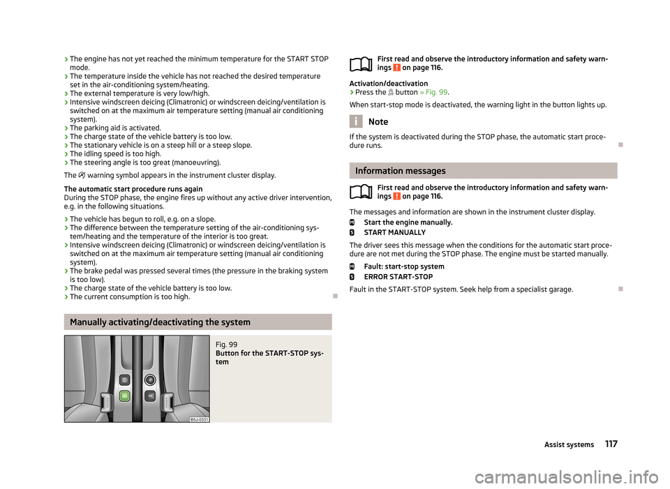
Manually activating/deactivating the system
Fig. 99
Button for the START-STOP sys-
tem
First read and observe the introductory information and safety warn-
ings on page 116.
Activation/deactivation
›
Press the button » Fig. 99 .
When start-stop mode is deactivated, the warning light in the button lights up.
Note
If the system is deactivated during the STOP phase, the automatic start proce-
dure runs.
Information messages
First read and observe the introductory information and safety warn-
ings
on page 116.
The messages and information are shown in the instrument cluster display.
Start the engine manually.START MANUALLY
The driver sees this message when the conditions for the automatic start proce- dure are not met during the STOP phase. The engine must be started manually.
Fault: start-stop system
ERROR START-STOP
Fault in the START-STOP system. Seek help from a specialist garage.
117Assist systems
Page 153 of 223
WARNINGObserve the following instructions for the airbag system.■It is prohibited to tamper with individual parts of the airbag system as this
might result in the airbag being deployed.■
Never install any airbag parts into the vehicle that have been removed from
old cars or have been recycled.
■
Never fit damaged airbag parts to a vehicle. The airbags may then not be
triggered properly or not at all in the event of an accident.
■
No modifications of any kind must be made to parts of the airbag system.
WARNING■ A change in the suspension of the vehicle including the use of non-approved
wheels and tyre combinations can alter the functioning of the airbag system -
there is a risk of accident and fatal injury.■
Never make any changes to the front bumper or bodywork.
Washing the car
Introduction
This chapter contains information on the following subjects:
Washing by hand
150
Automatic car wash systems
151
Washing with a high-pressure cleaner
151
The best protection for your vehicle against harmful environmental influences is
frequent washing.
How often the vehicle should be washed depends, for example, on the following
factors.
› Frequency of use.
› Parking situation (garage, under trees, etc.).
› Season of the year.
› Weather conditions.
› Environmental influences.
The longer insect residues, bird droppings, tree sap, road and industrial dust, tar,
soot particles, road salt and other aggressive deposits remain adhering to the
paintwork of your vehicle, the more detrimental their destructive effect can be.
High temperatures, such as those caused by intensive sun's rays, accentuate this
caustic effect.
It is essential to also thoroughly clean the underside of the vehicle at the end of
the winter.WARNING■ Washing your vehicle in the winter: water and ice in the brake system can
affect the braking efficiency – there is the risk of an accident.■
Only wash the vehicle when the ignition is switched off – there is the risk of
an accident.
CAUTION
Do not wash your vehicle in bright sunlight – there is a risk of paint damage.
For the sake of the environment
Only wash the vehicle at washing bays intended for this purpose.
Washing by hand
First read and observe the introductory information and safety warn-
ings
on page 150.
Soften the dirt with plenty of water and rinse as much as you can of this off.
Clean the vehicle with a soft sponge, a washing glove or a washing brush . Work
from the top to the bottom - starting with the roof.
Only use a car shampoo for stubborn dirt.
Wash out the sponge or washing glove thoroughly at short intervals.
Clean wheels, door sills and similar parts last. Use a second sponge for such
areas.
Give the vehicle a good rinse after washing it and dry it off using a chamois leath- er.
150General Maintenance
Page 196 of 223
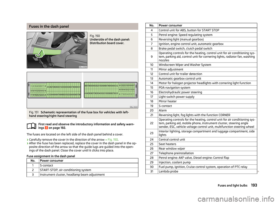
Fuses in the dash panelFig. 150
Underside of the dash panel:
Distribution board cover.
Fig. 151
Schematic representation of the fuse box for vehicles with left-
hand steering/right-hand steering
First read and observe the introductory information and safety warn-
ings
on page 192.
The fuses are located on the left side of the dash panel behind a cover.
› Carefully remove the cover in the direction of the arrow
» Fig. 150.
› After the fuse has been replaced, replace the cover in the dash panel in the op-
posite direction of the arrow so that the guide lugs are guided into the open- ings of the dash panel. Close the cover until it clicks into place.
Fuse assignment in the dash panel
No.Power consumer1S-contact2START-STOP, air-conditioning system3Instrument cluster, headlamp beam adjustmentNo.Power consumer4Control unit for ABS, button for START STOP5Petrol engine: Speed regulating system6Reversing light (manual gearbox)7Ignition, engine control unit, automatic gearbox8Brake pedal switch, clutch pedal switch9Operating controls for the heating, control unit for air conditioning sys-
tem, parking aid, control unit for cornering lights, radiator fan, washing nozzles10Windscreen Wiper and Washer System11Mirror adjustment12Control unit for trailer detection13Automatic gearbox control unit14Motor for halogen projector headlights with cornering light function15PDA navigation system16Electrohydraulic power steering17Light switch power supply18Mirror heater19S-contact20Alarm21Reversing light, fog lights with the function CORNER22Operating controls for the heating, control unit for air conditioning sys-
tem, parking aid, mobile phone, instrument cluster, steering angle
sender, ESC, vehicle voltage control unit, multifunction steering wheel23Interior lighting, storage compartment and luggage compartment, side
lights24Central control unit25Seat heaters26Rear window wiper27Telephone preinstallation28Petrol engine: AKF valve, Diesel engine: Control flap29Injection, coolant pump30Fuel pump, ignition, Cruise control system, operation of PTC relay31Lambda probe 193Fuses and light bulbs