ESP SKODA FABIA 2014 2.G / 5J User Guide
[x] Cancel search | Manufacturer: SKODA, Model Year: 2014, Model line: FABIA, Model: SKODA FABIA 2014 2.G / 5JPages: 197, PDF Size: 13.56 MB
Page 46 of 197
Note■The system has to be synchronised, if the vehicle cannot be unlocked or
locked with the remote control key after replacing the battery » page 49.■
Replacing the battery in the key a glued decorative cover requires the cover
to be destroyed. A replacement cover can be purchased from a ŠKODA Partner.
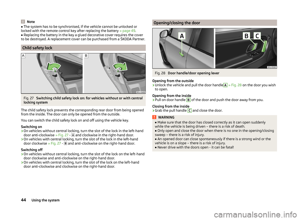
Child safety lock
Fig. 27
Switching child safety lock on: for vehicles without or with central
locking system
The child safety lock prevents the corresponding rear door from being opened
from the inside. The door can only be opened from the outside.
You can switch the child safety lock on and off using the vehicle key.
Switching on
›
On vehicles without central locking, turn the slot of the lock in the left-hand
door anti-clockwise » Fig. 27 -
and clockwise in the right-hand door.
›
On vehicles with central locking, turn the slot of the lock in the left-hand
door clockwise » Fig. 27 -
and anti-clockwise on the right-hand door.
Switching off
›
On vehicles without central locking, turn the slot of the lock on the left-hand
door clockwise and anti-clockwise on the right-hand door.
›
On vehicles with central locking, turn the slot of the lock on the left-hand
door anti-clockwise and clockwise on the right-hand door.
Opening/closing the doorFig. 28
Door handle/door opening lever
Opening from the outside
›
Unlock the vehicle and pull the door handle
A
» Fig. 28 on the door you wish
to open.
Opening from the inside
›
Pull on door handle
B
of the door and push the door away from you.
Closing from the inside
›
Grab the pull handle
C
and close the door.
WARNING■ Make sure that the door has closed correctly as it can open suddenly
while the vehicle is being driven – there is a risk of death.■
Only open and close the door when there is no one in the opening/closing
sweep – there is a risk of injury.
■
An opened door can close spontaneously if there is a strong wind or the
vehicle is on a slope – there is a risk of injury.
■
Never drive with the doors open - it can be fatal!
44Using the system
Page 48 of 197
Warning light in the driver's door
After locking the vehicle, the warning light flashes for around 2 seconds in
quick succession, afterwards it begins to flash evenly at longer intervals.
If the vehicle is locked and the safe securing system » page 46 is not operat-
ing, the warning light in the driver door flashes for about 2 seconds fast, goes
out and starts to flash evenly at longer intervals after about 30 seconds.
If the indicator light first flashes fast for about 2 seconds, then lights up for
about 30 seconds continuously and then flashes slowly, there is a fault in the
central locking system or in the interior monitor and in the towing protec-
tion » page 50 . Seek help from a specialist garage.
Convenience operation of windows
The windows can be opened and closed when unlocking and locking the vehi-
cle » page 53 .
CAUTION
If the safe securing system is activated » page 46, the door opening lever and
the central locking buttons do not operate.
Note
■ In the event of an accident in which the airbags are deployed, the locked
doors are automatically unlocked in order to enable rescuers to gain access to
the vehicle.■
Upon failure of the central locking system the key can only be used for lock-
ing and unlocking the driver's door. The other doors and the boot lid can be
manually locked or unlocked. ■ Emergency locking of the door » page 45.
■ Emergency unlocking of the boot lid » page 51.
Individual settings
Read and observe
on page 46 first.
Opening a single door
This selection function makes it possible to only unlock the driver's door. The other doors remain locked and are only unlocked when the command is repea-
ted.
Automatic locking and unlocking
All the doors and the boot lid are locked automatically once the car reaches a
speed of about 15 km/h.
If the ignition key is withdrawn, the car is then automatically unlocked again.
In addition, it is possible for the driver or front passenger to unlock the car by
pressing the central locking button
» page 47 .
The doors can be unlocked and opened from the inside by a single pull on the
opening lever of the respective door.
Note
Individual settings can be applied in a specialist workshop.
Safe securing
Read and observe
on page 46 first.
The central locking system is equipped with a safe securing system. The door
locks are blocked automatically if the vehicle is locked from the outside. It is
then not possible to open the doors with the door handle, either from the in-
side or from the outside.
You will be informed that the safe securing system is activated after the vehi-
cle is locked by the CHECK DEADLOCK message on the instrument cluster dis-
play. On vehicles equipped with the MAXI DOT display, the display shows
Check deadlock. Log book!
Switching off
Opening can take place in one of the following ways.
›
By locking twice within 2 seconds.
›
By disabling the interior monitoring » page 50, Interior monitor and towing
protection .
If the vehicle is locked and the safe securing system is switched off, the door can be opened separately from the inside by a single pull on the opening lever.
Switching on
The safelock switches on automatically the next time the vehicle is locked and
unlocked.
Switch-on display
The warning light flashes for around 2 seconds in quick succession, afterwards
it begins to flash evenly at longer intervals.
Switch-off display
The indicator light in the driver door flashes for about 2 seconds fast, goes out
and starts to flash regularly at longer intervals after about 30 seconds.
46Using the system
Page 49 of 197
WARNINGIf the car is locked from the outside and the safelock system is switched on,
no-one must be in the car, as it is then not possible to open either a door or
a window from the inside. The locked doors make it more difficult for rescu-
ers to get into the vehicle in an emergency – risk to life!
Note
This function is only enabled in certain countries.
Unlocking the vehicle using the key
Fig. 31
Turning the key for unlocking
and locking the vehicle
Read and observe on page 46 first.
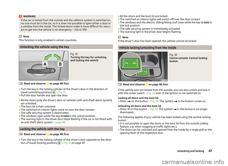
›
Turn the key in the locking cylinder of the driver's door in the direction of
travel (unlocking position)
A
» Fig. 31 .
›
Pull the door handle and open the door.
› All the doors (only the driver's door on vehicles with anti-theft alarm system)
are unlocked.
› The boot lid is then unlocked.
› The switched on interior lights come on over the door contact.
› The safe securing system is deactivated.
› The windows open while the key
is held in the unlock position.
› The warning light in the driver door stops flashing if the car is not fitted with
an anti-theft alarm system » page 49.
Locking the vehicle with the key
Read and observe
on page 46 first.
›
Turn the key in the locking cylinder of the driver's door opposite to the direc-
tion of travel (locking position)
B
» Fig. 31 on page 47 .
›All the doors and the boot lid are locked.
› The switched on interior lights will switch off over the door contact.
› The windows and the electric sliding/tilting roof close while the key
is held in
the lock position.
› The safe securing system is immediately activated.
› The warning light in the driver door begins flashing.
Note
If the driver's door has been opened, the vehicle cannot be locked.
Vehicle locking/unlocking from the inside
Fig. 32
Centre console: Central locking
button
Read and observe on page 46 first.
If the vehicle was not locked from the outside, you can also unlock and lock it
with the rocker switch » Fig. 32 even if the ignition is not switched on.
Locking all doors and the boot lid
›
Press
on the button » Fig. 32. The symbol
in the button comes on.
Unlocking all doors and the boot lid
›
Press
on the button » Fig. 32. The symbol
in the button is no longer
illuminated.
The following applies if your vehicle has been locked using the central locking button.
› It is not possible to open the doors or the boot lid from the outside (safety
feature, e.g. when stopping at traffic lights etc.).
› The doors can be unlocked and opened from the inside by a single pull on the
opening lever of the respective door.
47Unlocking and locking
Page 55 of 197
Power window force limiterRead and observe
and on page 51 first.
The electrical power windows are fitted with a force limiter. It reduces the risk
of bruises or injuries when closing the windows.
If there is an obstacle, the closing process is stopped and the window goes
down by several centimetres.
If the obstacle prevents the window from being closed during the next 10 sec-
onds, the closing process is interrupted once again and the window goes down
by several centimetres.
If you attempt to close the window again within 10 seconds of the window be-
ing moved down for the second time, even though the obstacle was not yet
been removed, the closing process is only stopped. During this time it is not
possible to automatically close the window. The force limiter is still switched
on.
The force limiter is only switched off if you attempt to close the window again
within the next 10 seconds - the window will now close with full force!
If you wait longer than 10 seconds, the force limiter is switched on again.
Window convenience operation
Read and observe
and on page 51 first.
The comfort controls of the windows provide the ability to open or close all the
windows at once.
Opening can take place in one of the following ways.
Opening
›
Press the symbol button on the remote control key and hold.
›
Hold the key in the driver's lock in the unlock position.
›
Hold button
A
» Fig. 37 on page 52 in the opening position.
Closing
›
Press the symbol button on the remote control key and hold.
›
Hold the key in the driver's lock in the lock position.
›
Hold Button
A
» Fig. 37 on page 52 in the closing position.
The movement of the window is immediately stopped by releasing the key or
the respective button.
Operational faults
Read and observe
and on page 51 first.
Electrical power windows do not operate
If the battery has been disconnected and then reconnected while the window was opened, the electrical power windows will not operate. The system must
be activated. Proceed as follows to re-establish the function.
› Switch on the ignition.
› Pull the top edge of the button in the driver's door and close the window.
› Release the button.
› Pull the relevant button upwards again for another approximately 3 seconds
and hold.
Operation in winter
In the winter, ice on the window may cause greater resistance as the window
is closed. The window will stop and open again by several centimetres.
It is necessary to deactivate the force limiter to close the window » page 53.
Electric sliding/tilting roof
Introduction
This chapter contains information on the following subjects:
Operation
54
Comfort operation
54
Emergency operation
55
The sliding/tilting roof is operated with the rotary switch » Fig. 38 on
page 54 and only works when the ignition is switched on. The control dial
has several positions.
The sliding/tilting roof can still be opened, closed and tilted for approx. 10 mi-
nutes after switching the ignition off. However, as soon as one of the front
doors is opened it is no longer possible to operate the sliding/tilting roof.
WARNINGClose the sliding/tilting roof carefully – risk of injury. 53Unlocking and locking
Page 57 of 197
Emergency operationFig. 39
Point for positioning screwdriver/opening for positioning the key
Read and observe
and on page 53 first.
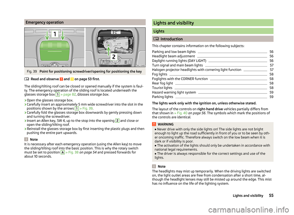
The sliding/tilting roof can be closed or opened manually if the system is faul-
ty. The emergency operation of the sliding roof is located underneath the
glasses storage box
1
» page 82 , Glasses storage box .
›
Open the glasses storage box.
›
Carefully insert an approximately 5 mm wide screwdriver into the slot in the
positions shown by the arrows
1
» Fig. 39 .
›
Carefully fold the glasses storage box downwards by gently pressing down
and turning the screwdriver.
›
Insert an Allen key, SW 4, up to the stop into the opening
2
and close or
open the sliding/tilting roof.
›
Reinstall the glasses storage box by first inserting the plastic plugs and then
pushing the entire part upwards.
Note
It is necessary after each emergency operation (using the Allen key) to move
the sliding/tilting roof into the basic position. This is why the rotary switch
must be set to position A
» Fig. 38 on page 54 and pressed forwards for
about 10 seconds.
Lights and visibility
Lights
Introduction
This chapter contains information on the following subjects:
Parking and low beam lights
56
Headlight beam adjustment
56
Daylight running lights (DAY LIGHT)
56
Turn signal and main beam lights
57
Halogen projector headlights with cornering light function
57
Fog lights
58
Foglights with the CORNER function
58
Rear fog light
58
Tourist lights
58
Hazard warning light system
59
Parking lights
59
The lights work only with the ignition on, unless otherwise stated.
The layout of the controls on right-hand drive vehicles partially differs from
that shown in » Fig. 40 on page 56 . The symbols which mark the positions of
the controls are identical.
WARNING■ Never drive with only the side lights on! The side lights are not bright
enough to light up the road sufficiently in front of you or to be seen by oth-
er oncoming traffic. Therefore always switch on the low beam when it is
dark or if visibility is poor.■
The activation of the lights should only be undertaken in accordance with
national legal requirements.
■
The driver is always responsible for the correct settings and use of the
lights.
Note
The headlights may mist up temporarily. When the driving lights are switched
on, the light outlet areas are free from condensation after a short time, al-
though the headlight lenses may still be misted up around the edge. This mist
has no influence on the life of the lighting system.55Lights and visibility
Page 58 of 197
Parking and low beam lightsFig. 40
Dash panel: Light switch
Read and observe on page 55 first.
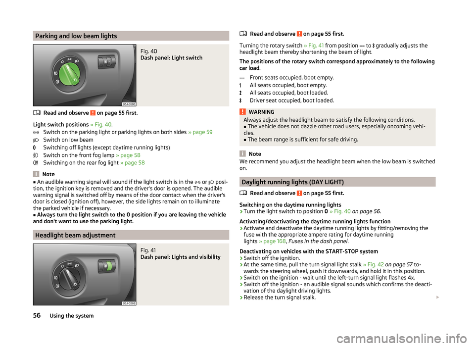
Light switch positions » Fig. 40 .
Switch on the parking light or parking lights on both sides » page 59
Switch on low beam
Switching off lights (except daytime running lights)
Switch on the front fog lamp » page 58
Switching on the rear fog light » page 58
Note
■
An audible warning signal will sound if the light switch is in the or posi-
tion, the ignition key is removed and the driver's door is opened. The audible
warning signal is switched off by means of the door contact when the driver's
door is closed (ignition off), however, the side lights remain on to illuminate
the parked vehicle if necessary.■
Always turn the light switch to the 0 position if you are leaving the vehicle
and don't want to use the parking light.
Headlight beam adjustment
Fig. 41
Dash panel: Lights and visibility
Read and observe on page 55 first.
Turning the rotary switch » Fig. 41 from position
to
gradually adjusts the
headlight beam thereby shortening the beam of light.
The positions of the rotary switch correspond approximately to the following
car load.
Front seats occupied, boot empty.
All seats occupied, boot empty.
All seats occupied, boot loaded.
Driver seat occupied, boot loaded.
WARNINGAlways adjust the headlight beam to satisfy the following conditions.■The vehicle does not dazzle other road users, especially oncoming vehi-
cles.■
The beam range is sufficient for safe driving.
Note
We recommend you adjust the headlight beam when the low beam is switched
on.
Daylight running lights (DAY LIGHT)
Read and observe
on page 55 first.
Switching on the daytime running lights
›
Turn the light switch to position 0 » Fig. 40 on page 56 .
Activating/deactivating the daytime running lights function
›
Activate and deactivate the daytime running lights by fitting/removing the
fuse with the appropriate ampere rating for daytime running
lights » page 168 , Fuses in the dash panel .
Deactivating on vehicles with the START-STOP system
›
Switch off the ignition.
›
At the same time, pull the turn signal light stalk » Fig. 42 on page 57 to-
wards the steering wheel, push it downwards, and hold it in this position.
›
Switch on the ignition - wait until the left-turn signal light flashes 4x.
›
Switch off the ignition - an audible signal sounds which confirms the deacti-
vation of the daylight driving lights.
›
Release the turn signal stalk.
56Using the system
Page 70 of 197
Adjusting the head restraintsFig. 59
Head restraint: adjusting/removing
Setting the height
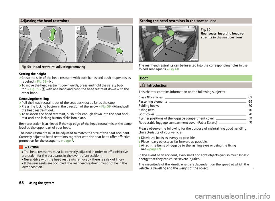
›
Grasp the side of the head restraint with both hands and push it upwards as
required » Fig. 59 -
.
›
To move the head restraint downwards, press and hold the safety but-
ton » Fig. 59 -
with one hand and push the head restraint down with the
other hand.
Removing/installing
›
Pull the head restraint out of the seat backrest as far as the stop.
›
Press the locking button in the direction of the arrow » Fig. 59 -
and pull
the head restraint out.
›
To re-insert the head restraint, push it far enough down into the seat back-
rest until the locking button clicks into place.
Best protection is achieved if the top edge of the head restraint is at the same
level as the upper part of your head.
The head restraints must be adjusted to match the size of the seat occupant.
Correctly adjusted head restraints together with the seat belts offer effective
protection for the occupants » page 7.
WARNING■
The head restraints must be correctly adjusted in order to offer effective
protection for the occupants in the event of an accident.■
Never drive with the head restraints removed - there is a risk of injury.
■
If the rear seats are occupied, the rear head restraint must not be in the
lower position.
Storing the head restraints in the seat squabsFig. 60
Rear seats: Inserting head re-
straints in the seat cushions
The rear head restraints can be inserted into the corresponding holes in the folded seat squabs » Fig. 60.
Boot
Introduction
This chapter contains information on the following subjects:
Class N1 vehicles
69
Fastening elements
69
Folding hooks
70
Fixing nets
70
Boot cover
70
Further positions of the luggage compartment cover
71
Retractable luggage compartment cover (Fabia Estate)
71
Please observe the following for the purpose of maintaining good handling
characteristics of your vehicle:
›
Distribute loads as evenly as possible.
›
Place heavy objects as far forward as possible.
›
Attach the items of luggage to the lashing eyes or using the fixing
net » page 69 .
In the event of an accident, even small and light objects gain so much kinetic
energy that they can cause severe injuries.
The magnitude of the kinetic energy is dependent on the speed at which the
vehicle is travelling and the weight of the object.
68Using the system
Page 71 of 197
Example: In the event of a frontal collision at a speed of 50 km/h, an object
weighing 4.5 kg produces energy corresponding to 20 times its own weight.
This means that it results in a weight of approx. 90 kg “ ”.WARNING■ Store the objects in the boot and attach them to the lashing eyes.■Loose objects can be thrown forward during a sudden manoeuvre or in
case of an accident and can injure the occupants or other road users.■
Loose objects could hit a deployed airbag and injure occupants – there is
a risk of death.
■
Please note that the handling properties of the vehicle may be affected
when transporting heavy objects as the centre of gravity can be shifted –
there is a risk of an accident. The speed and style of driving must be adjus-
ted accordingly.
■
If the items of luggage or objects are attached to the lashing eyes with
unsuitable or damaged lashing straps, injuries can occur in the event of
braking manoeuvres or accidents. To prevent items of luggage from being
thrown forward, always use suitable lashing straps which must be firmly at-
tached to the lashing eyes.
■
Items carried in the luggage compartment must be stowed in such a way
that no objects are able to slip forward under sudden driving manoeuvres
or braking – there is a risk of injury.
■
When transporting fastened objects which are sharp and dangerous in
the boot that has been enlarged by folding the rear seats forward, ensure
the safety of the passengers transported on the other rear seats » page 9,
Correct seated position of the rear seat passengers .
■
If the rear seat next to the folded forward seat is occupied, ensure maxi-
mum safety, e.g. by placing the goods to be transported in such a way that
the seat is prevented from folding back in case of a rear collision.
■
Never drive with the tailgate fully opened or slightly ajar otherwise ex-
haust gases may get into the interior of the vehicle – risk of poisoning.
■
Under no circumstances, should the permissible axle loads and permissi-
ble gross weight of the vehicle be exceeded – there is the risk of an acci-
dent.
■
Never transport people in the boot!
CAUTION
Please ensure that the heating elements for the rear window heater are not
damaged as a result of abrasive objects.NoteTyre pressure must be adjusted to the load » page 151, Tyre service life .
Class N1 vehicles
Read and observe
and on page 69 first.
On class N1 vehicles, which are not fitted with a protective grille, a lashing set
which complies with the standard EN 12195 (1 - 4) must be used for fastening
the load.
The proper functioning of the electrical system is essential for the safe opera-
tion of the vehicle. It is important to ensure that it is not damaged during mod-
ifications or when loading or unloading the luggage compartment.
Fastening elements
Fig. 61
Boot: Lashing eyes and fastening elements
Read and observe
and on page 69 first.
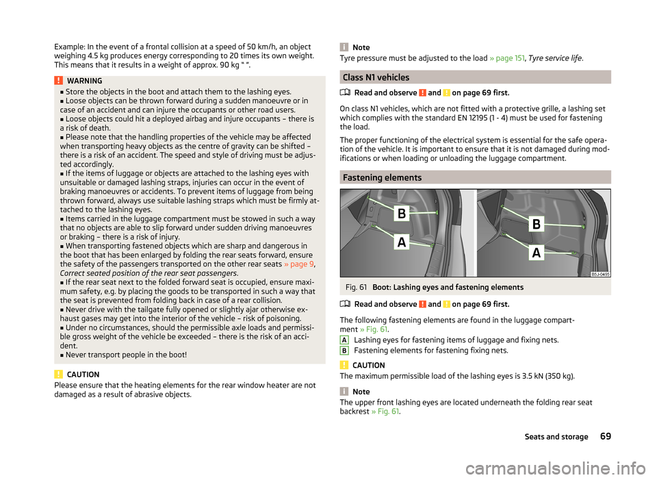
The following fastening elements are found in the luggage compart-
ment » Fig. 61 .
Lashing eyes for fastening items of luggage and fixing nets.
Fastening elements for fastening fixing nets.
CAUTION
The maximum permissible load of the lashing eyes is 3.5 kN (350 kg).
Note
The upper front lashing eyes are located underneath the folding rear seat
backrest » Fig. 61.AB69Seats and storage
Page 90 of 197

The cooling system operates only if the following conditions are met.The cooling system is switched on » page 88.
The engine is running.
The outside temperature is above approximately +2 °C.
The blower switch is switched on (positions 1-4).
If the desired interior temperature can also be achieved without activating the
cooling system, fresh air mode should be selected.
If the coolant temperature is too high, the cooling system is switched off to
ensure that the engine cools down.
CAUTION
■ Under certain circumstances, air at a temperature of about 5 °C can flow out
of the vents when the cooling system is switched on.■
Lengthy and uneven distribution of the air flow out of the vents (especially
around the feet) and large differences in temperature, for example, when get-
ting out of the vehicle, can cause susceptible individuals to catch a cold.
Note
■ We recommend that you have the air conditioning system cleaned by a spe-
cialist garage once every year.■
During operation of the air conditioning, under certain circumstances an in-
crease in engine idle speed may occur in order to ensure sufficient heating
comfort.
OperationFig. 96
The air conditioning system: Control elements
Read and observe
on page 88 first.
Functions of the individual controls » Fig. 96 :
Set the temperature (turn to the left: to reduce the temperature, turn to
the right: to increase the temperature)
Set the blower level (level 0: blowers off, level 4: the highest blower
speed)
Set the direction of the air outlet » page 85
Switch recirculation on/off » page 89
Switch the cooling system on/off
Note
The warning light in the symbol button lights after activation, even if not all
of the conditions for the function of the cooling system are met » page 87. The
operational readiness of the cooling system is indicated by the indicator light
in the button lighting up.ABC88Using the system
Page 93 of 197
Switch recirculation on/off » page 91
Switch the cooling system on/off
Note
Do not stick anything on or cover the interior temperature sensor 11 » Fig. 97 ;
it could have an unfavourable effect on the Climatronic system.
Automatic mode
The automatic mode is used in order to maintain a constant temperature and
to demist the windows in the interior of the car.
Switching on
›
Set a temperature between +18 °C and +29 ℃.
›
Move the air outlet vents 3 » Fig. 94 on page 85 and 4 so that the air flow is
directed slightly upwards.
›
Press the button
» Fig. 97 on page 90 ;
will appear in the display.
Automatic mode can be switched off by pressing any of the air distribution
buttons or by increasing/decreasing the blower speed. The temperature is
nevertheless regulated.
Setting the temperature
Setting temperature
›
Switch on the ignition.
›
Turn the control dial
1
» Fig. 97 on page 90 to the left or to the right to in-
crease or decrease the temperature.
Switching between Celsius and Fahrenheit
›
Press and hold the and
buttons simultaneously.
The information appears in the display in the desired temperature unit (no.
3
» Fig. 97 on page 90 ).
The interior temperature can be set between +18 °C and +29 ℃. The interior
temperature is regulated automatically within this range.
If you set the temperature below +18 ℃, “LO” appears in the display.
If you set a temperature higher than +29 ℃, “HI” appears in the display.
In both end positions, the Climatronic operates at maximum cooling or heating capacity. There is therefore no automatic temperature control.
CAUTIONLengthy and uneven distribution of the air flow out of the vents (especially
around the feet) and large differences in temperature, for example, when get-
ting out of the vehicle, can cause susceptible individuals to catch a cold.
Recirculated air mode
Recirculated air mode prevents polluted air from outside the vehicle getting in-
to the vehicle, for example when driving through a tunnel or when standing in
a traffic jam.
Switching on
›
Press the button
» Fig. 97 on page 90 .
The display shows the icon.
Switching off
›
Press the button
» Fig. 97 on page 90 again.
The icon in the display goes out.
WARNINGNever leave recirculated air mode on over a longer period, as “stale air” can
cause fatigue in the driver and the passengers, reduce attention levels and
also cause the windows to mist up. The risk of having an accident increa-
ses. Switch off recirculated air mode as soon as the windows start to mist
up.
Note
If recirculated air mode is switched on for around 15 minutes, the symbol
will begin to flash in the display as a sign that the recirculated air mode is
switched on long-term. If the recirculated air mode is not switched off, the
symbol flashes for around 5 minutes.
Controlling the blower
The Climatronic system controls the blower stages automatically in line with
the interior temperature. However, the blower level can be manually adjusted
to suit your particular needs.
›
Turn control dial
10
» Fig. 97 on page 90 to the left or to the right to increase
or decrease the blower speed.
If the blower is switched off, the Climatronic system is switched off.
91Heating and air conditioning