turn signal SKODA FABIA 2014 3.G / NJ Operating Instruction Manual
[x] Cancel search | Manufacturer: SKODA, Model Year: 2014, Model line: FABIA, Model: SKODA FABIA 2014 3.G / NJPages: 216, PDF Size: 30.9 MB
Page 57 of 216
Downloaded from www.Manualslib.com manuals search engine Displaying an error
If the warning icon in the driver's door initially flashes quickly for around 2 sec-
onds, and then lights up for 30 seconds without interruption before flashing
again slowly, you will need to seek the assistance of a specialist garage.
Discharged battery in the remote control key
If the red warning light B
» Fig. 34 on page 50 does not flash when you press
a button on the remote control key the battery is dead.
If the voltage of the battery in the remote control key is too low, the following
message appears in the display of the instrument cluster.
Change the key battery!
KEY BATTERY PLEASE CHANGE
Replace the battery » page 177.
Anti-theft alarm system
Introduction
This chapter contains information on the following subjects:
Activating/deactivating
54
Interior monitor and towing protection
55
The anti-theft alarm system increases the level of protection against theft and
break-in.
The alarm system triggers audible and visual signals if an attempt is made to
break into the vehicle (hereafter referred to only as alarm).
Triggering the alarm
The alarm is triggered when the following unauthorized actions are carried out
on the locked vehicle.
› Opening the bonnet.
› Opening the boot lid.
› Opening the doors.
› Manipulation of the ignition lock.
› Towing the vehicle
» page 55.
› Movement in the vehicle
» page 55.
› Sudden and significant voltage failure of the electrical system.
› Uncoupling the trailer
» page 133, Trailer, connect and disconnect .
If the driver's door of a vehicle with a remote control is unlocked and opened
by the lock cylinder, then the alarm is triggered.
Switching off the alarm
The alarm is turned off by pressing the button on the radio remote control
key or switching on the ignition.
CAUTION
Before leaving the vehicle, check that the doors and windows are closed in or-
der to ensure that the alarm system is fully operational.
Note
The working life of the alarm siren is 5 years.
Activating/deactivating
Read and observe
on page 54 first.
Activating
The alarm system is activated automatically approximately 30 seconds after
the vehicle is locked.
If the vehicle is unlocked and a door or the boot lid not opened within the next
45 seconds, the vehicle will lock again automatically and the SafeLock system
or anti-theft alarm system will be switched back on. This function is intended
to prevent the car being unlocked unintentionally.
Deactivating
The alarm system is deactivated automatically after the vehicle is unlocked. If
the vehicle is not opened within 45 seconds, the alarm system is automatically
activated again.
The alarm system is also deactivated if you unlock the driver door using the
key within 45 seconds of locking the vehicle.
54Operation
Page 62 of 216
Downloaded from www.Manualslib.com manuals search engine If you attempt to close the window again within 10 seconds of the window be-
ing moved down for the second time, even though the obstacle was not yet
been removed, the closing process is only stopped. During this time it is not
possible to automatically close the window. The force limiter is still switched
on.
The force limiter is only switched off if you attempt to close the window again
within the next 10 seconds - the window will now close with full force!
If you wait longer than 10 seconds, the force limiter is switched on again.WARNING■ Variant 1 of the power window » Fig. 43 on page 57 has no force limiter.
The windows should be closed carefully – risk of injury.■
The passenger window in variant 2 of the power window » Fig. 43 on
page 57 has no force limiter. The window should nevertheless be closed
carefully – risk of injury!
Operational faults
Read and observe
and on page 56 first.
The electric window levers do not work if the vehicle battery has been discon-nected and connected again while a window was open. The system must be
activated.
Activation sequence:
›
Switch on the ignition.
›
Pull the top edge of the button and close the window.
›
Release the button.
›
Pull the relevant button upwards again for approx. 1 seconds, and keep it
pressed down.
Lights and visibility
Lights
Introduction
This chapter contains information on the following subjects:
Operating the lights
60
Daylight running lights (DAY LIGHT)
60
Turn signal and main beam
61
Automatic driving lamp control
61
Fog lights
62
Fog lights with the CORNER function
62
Rear fog light
62
COMING HOME / LEAVING HOME
63
Hazard warning light system
63
Parking lights
63
Driving abroad
64
The lights work only with the ignition on, unless otherwise stated.
The layout of the controls on right-hand drive vehicles differs partially from
that shown in » Fig. 45 on page 60 . The symbols which mark the positions of
the controls are identical.
Keep the headlights lenses clean » page 143, Headlight glasses .
WARNING■
The activation of the lights should only be undertaken in accordance with
national legal requirements.■
The automatic driving lamp control
only operates as a support and
does not release the driver from his responsibility to check the lights and, if
necessary, to switch on the light depending on the prevailing light condi-
tions.
59Lights and visibility
Page 64 of 216
Downloaded from www.Manualslib.com manuals search engine ›Hold the operating lever in this position for at least 3 seconds after switching
the ignition on.
The deactivation of the function is confirmed by an audible signal.
Activating on vehicles without Infotainment›
Switch off the ignition.
›
Pull the indicator / main beam lever towards the steering wheel, push up and
hold in this position.
›
Switch on the ignition.
›
Hold the operating lever in this position for at least 3 seconds after switching
the ignition on.
The activation of the function is confirmed by an audible signal.
WARNINGWhen the daytime running light is switched on, the parking lights (neither
at the front nor the rear) and the number plate lights are not lit. Therefore
always switch on the low beam when the visibility is poor.
Turn signal and main beam
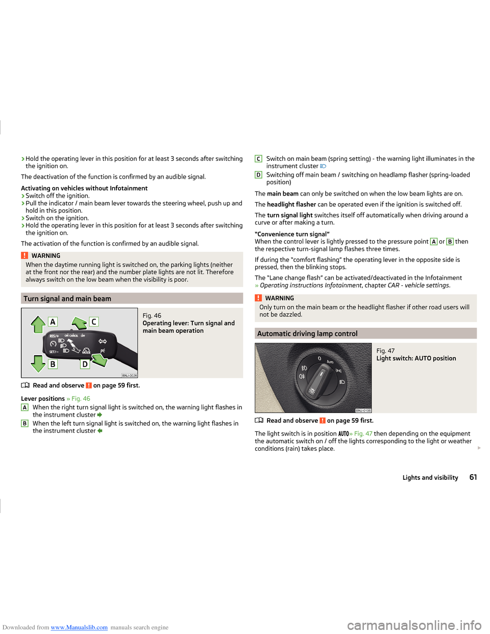
Fig. 46
Operating lever: Turn signal and
main beam operation
Read and observe on page 59 first.
Lever positions » Fig. 46
When the right turn signal light is switched on, the warning light flashes in
the instrument cluster
When the left turn signal light is switched on, the warning light flashes in
the instrument cluster
ABSwitch on main beam (spring setting) - the warning light illuminates in the
instrument cluster
Switching off main beam / switching on headlamp flasher (spring-loaded
position)
The main beam can only be switched on when the low beam lights are on.
The headlight flasher can be operated even if the ignition is switched off.
The turn signal light switches itself off automatically when driving around a
curve or after making a turn.
“Convenience turn signal”
When the control lever is lightly pressed to the pressure point A
or
B
then
the respective turn-signal lamp flashes three times.
If during the “comfort flashing” the operating lever in the opposite side is
pressed, then the blinking stops.
The “Lane change flash” can be activated/deactivated in the Infotainment
» Operating instructions Infotainment , chapter CAR - vehicle settings .
WARNINGOnly turn on the main beam or the headlight flasher if other road users will
not be dazzled.
Automatic driving lamp control
Fig. 47
Light switch: AUTO position
Read and observe on page 59 first.
The light switch is in position
» Fig. 47 then depending on the equipment
the automatic switch on / off the lights corresponding to the light or weather
conditions (rain) takes place.
CD61Lights and visibility
Page 65 of 216
Downloaded from www.Manualslib.com manuals search engine The sensitivity of the sensor for the determination of the ambient light can be
adjusted in the infotainment » Operating instructions Infotainment , chap-
ter CAR - vehicle settings .
If the light switch is in position
, the lettering
illuminates next to the
light switch. If the light is switched on automatically, the symbol
next to the
light switch also lights up.
Automatic driving-light control during rain
The dipped beam is switched on automatically if the following conditions are
met.
The parking aid is activated.
The light switch is in the position .
The windscreen wipers are on for more than 30 s.
The light turns off about 4 minutes after turning off the wipers.
Automatic headlight control in rain can be activated or deactivated in the Info-
tainment » Operating instructions Infotainment , chapter CAR - Vehicle set-
tings .
CAUTION
Poorer visibility is detected by a sensor mounted below the windscreen in the
holder of the inside mirror or in the control panel. Do not attach any stickers or
similar objects in front of the sensor in order to avoid impairing the function or
its reliability.
Fog lights
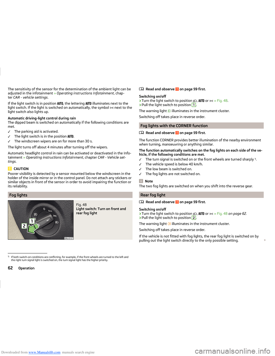
Fig. 48
Light switch: Turn on front and
rear fog light
Read and observe on page 59 first.
Switching on/off
›
Turn the light switch to position
,
or
» Fig. 48 .
›
Pull the light switch to position
1
.
The warning light
illuminates in the instrument cluster.
Switching off takes place in reverse order.
Fog lights with the CORNER function
Read and observe
on page 59 first.
The function CORNER provides better illumination of the nearby environmentwhen turning, manoeuvring or anything similar.
The function automatically switches on the fog lights on each side of the ve- hicle, if the following conditions are met.
The turn signal is switched on or the front wheels are turned sharply 1)
.
The vehicle speed is below 40 km/h.
The low beam is switched on.
The fog lights are not switched on.
Note
The two fog lights are switched on when you shift into the reverse gear.
Rear fog light
Read and observe
on page 59 first.
Switching on/off
›
Turn the light switch to position ,
or
» Fig. 48 on page 62 .
›
Pull the light switch to position
2
.
The warning light illuminates in the instrument cluster.
Switching off takes place in reverse order.
If the vehicle is not fitted with fog lights, the rear fog light is switched on by pulling out the light switch directly to the only possible setting.
1)
If both switch-on conditions are conflicting, for example, if the front wheels are turned to the left and
the right turn signal light is switched on, the turn signal light has the higher priority.
62Operation
Page 66 of 216
Downloaded from www.Manualslib.com manuals search engine NoteWhile driving with an accessory connected to the trailer socket (e.g. trailer,
bike carrier) only the equipment is illuminated by the fog light. The towing de-
vice must be installed at the factory or from the ŠKODA original accessories.
COMING HOME / LEAVING HOME
Read and observe
on page 59 first.
The function COMING HOME ensures that the vehicle's environment is illumi-
nated after switching off the ignition and opening the driver's door.
The function LEAVING HOME ensures that the vehicle's environment is illumi-
nated after unlocking the vehicle with the radio remote control unit.
The function switches the light on only if there is poorer visibility and the light
switch is in the position .
Enabling / disabling and setting functions
The functions and setting of the lighting duration can be activated or deactiva-
ted in the Infotainment system » Operating instructions Infotainment , chap-
ter CARVehicle settings .
CAUTION
■
Poorer visibility is detected by a sensor mounted below the windscreen in
the holder of the inside mirror or in the control panel. Do not attach any stick-
ers or similar objects in front of the sensor in order to avoid impairing the func-
tion or its reliability.■
If this option is always enabled, then the battery is heavily loaded.
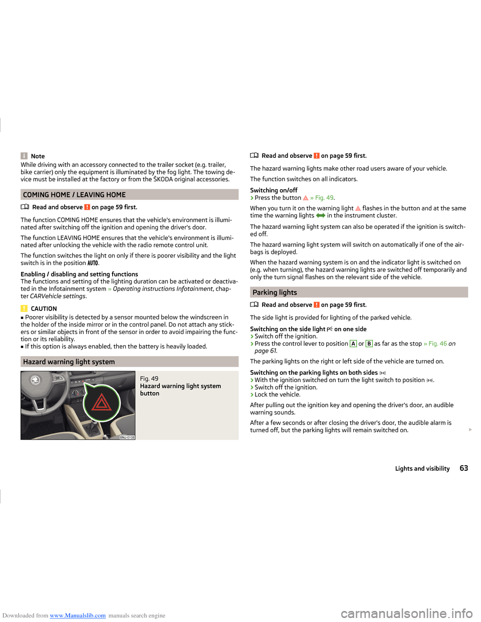
Hazard warning light system
Fig. 49
Hazard warning light system
button
Read and observe on page 59 first.
The hazard warning lights make other road users aware of your vehicle.
The function switches on all indicators.
Switching on/off
›
Press the button
» Fig. 49 .
When you turn it on the warning light
flashes in the button and at the same
time the warning lights
in the instrument cluster.
The hazard warning light system can also be operated if the ignition is switch-
ed off.
The hazard warning light system will switch on automatically if one of the air-
bags is deployed.
When the hazard warning system is on and the indicator light is switched on
(e.g. when turning), the hazard warning lights are switched off temporarily and
only the turn signal flashes on the relevant side of the vehicle.
Parking lights
Read and observe
on page 59 first.
The side light is provided for lighting of the parked vehicle.
Switching on the side light on one side
›
Switch off the ignition.
›
Press the control lever to position
A
or
B
as far as the stop
» Fig. 46 on
page 61 .
The parking lights on the right or left side of the vehicle are turned on.
Switching on the parking lights on both sides
›
With the ignition switched on turn the light switch to position .
›
Switch off the ignition.
›
Lock the vehicle.
After pulling out the ignition key and opening the driver's door, an audible
warning sounds.
After a few seconds or after closing the driver's door, the audible alarm is
turned off, but the parking lights will remain switched on.
63Lights and visibility
Page 106 of 216
Downloaded from www.Manualslib.com manuals search engine Switch ignition on / offRead and observe
and on page 102 first.
›
Press the button » Fig. 112 on page 102 briefly.
The ignition is switched on or off.
On vehicles fitted with a manual transmission, the clutch pedal must not be
depressed while switching the ignition on or off, otherwise the system would
try to start.
On vehicles fitted with a automatic transmission, the brake pedal must not be
depressed while switching the ignition on or off, otherwise the system would
try to start.
If the driver's door is opened while the ignition is on, an audible signal sounds
and the following message appears in the instrument cluster display.
Ignition switched on.
IGNITION STILL ON
When leaving the vehicle always switch off the ignition.
Starting the engine
Read and observe
and on page 102 first.
Procedure for starting the engine
›
Firmly apply the handbrake.
›
For vehicles with manual transmission , shift gear lever to neutral, depress
the clutch pedal and hold it there until the engine starts.
›
On vehicles with automatic transmission , place the selector lever in position
P or N and depress the brake pedal until the engine starts.
›
Press the starter button » Fig. 112 on page 102 briefly – the engine starts au-
tomatically.
In vehicles with diesel engines the glow plug warning light
lights up after
pressing the button. The engine can be started after the indicator light goes
out.
Note
■ The engine running noises may at first be louder for a short time after start-
ing the cold engine. This is quite normal and is not an operating problem.■
You should not switch on any major electrical components during the heat-
ing period otherwise the vehicle battery will be drained unnecessarily.
Switching off the engine
Read and observe
and on page 102 first.
Switching off
›
Stop the vehicle » page 107, Parking .
›
Press the button » Fig. 112 on page 102 briefly.
The engine and the ignition are switched off simultaneously.
Emergency shutdown
If necessary and in exceptional cases, the engine may even be turned off while
driving.
›
Press the starter button » Fig. 112 on page 102 for longer than 1 second or
twice within 1 second.
After the emergency stop of the engine, the steering lock will remain un-
locked.
CAUTION
Do not switch the engine off immediately at the end of your journey after the
engine has been operated over a prolonged period at high loads but leave it to
run at an idling speed for about 1 minute. This prevents any possible accumula-
tion of heat when the engine is switched off.
Note
The radiator fan can intermittently continue to run for approximately 10 mi-
nutes after the ignition has been switched off.103Starting-off and driving
Page 107 of 216
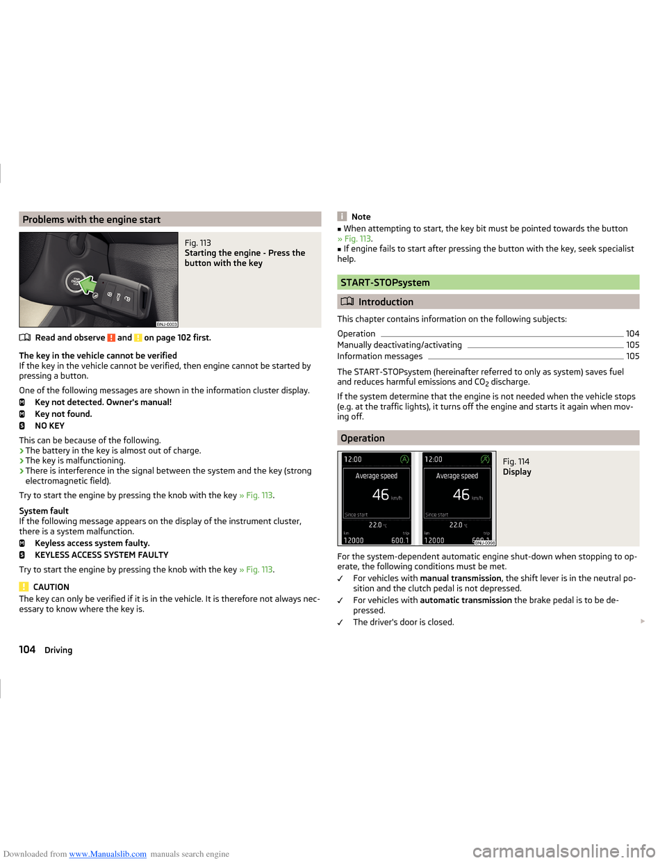
Downloaded from www.Manualslib.com manuals search engine Problems with the engine startFig. 113
Starting the engine - Press the
button with the key
Read and observe and on page 102 first.
The key in the vehicle cannot be verified
If the key in the vehicle cannot be verified, then engine cannot be started by
pressing a button.
One of the following messages are shown in the information cluster display. Key not detected. Owner's manual!
Key not found.
NO KEY
This can be because of the following.
› The battery in the key is almost out of charge.
› The key is malfunctioning.
› There is interference in the signal between the system and the key (strong
electromagnetic field).
Try to start the engine by pressing the knob with the key » Fig. 113.
System fault
If the following message appears on the display of the instrument cluster,
there is a system malfunction.
Keyless access system faulty.
KEYLESS ACCESS SYSTEM FAULTY
Try to start the engine by pressing the knob with the key » Fig. 113.
CAUTION
The key can only be verified if it is in the vehicle. It is therefore not always nec-
essary to know where the key is.Note■ When attempting to start, the key bit must be pointed towards the button
» Fig. 113 .■
If engine fails to start after pressing the button with the key, seek specialist
help.
START-STOPsystem
Introduction
This chapter contains information on the following subjects:
Operation
104
Manually deactivating/activating
105
Information messages
105
The START-STOPsystem (hereinafter referred to only as system) saves fuel
and reduces harmful emissions and CO 2 discharge.
If the system determine that the engine is not needed when the vehicle stops
(e.g. at the traffic lights), it turns off the engine and starts it again when mov-
ing off.
Operation
Fig. 114
Display
For the system-dependent automatic engine shut-down when stopping to op-
erate, the following conditions must be met.
For vehicles with manual transmission , the shift lever is in the neutral po-
sition and the clutch pedal is not depressed.
For vehicles with automatic transmission the brake pedal is to be de-
pressed.
The driver's door is closed.
104Driving
Page 179 of 216
Downloaded from www.Manualslib.com manuals search engine Vehicles with automatic transmission may be towed with a tow bar or a tow
rope or with the front wheels raised. If the vehicle is raised at rear, the auto-
matic gearbox is damaged!
Driver of the tow vehicle›
Engage the clutch gently when starting off or depress the accelerator partic-
ularly gently if the vehicle is fitted with an automatic gearbox.
›
Only then, approach correctly when the rope is taut.
The maximum towing speed is 50 km/h.
Driver of the towed vehicle
›
Switch on the ignition so that the steering wheel is not locked and so that
the turn signal lights, windscreen wipers and windscreen washer system can
be used.
›
Take the vehicle out of gear or move the selector lever into position N if the
vehicle is fitted with an automatic gearbox.
Please note that the brake servo unit and power steering only operate if the
engine is running. If the engine is not running, significantly more physical force
is required to depress the brake pedal and steer the vehicle.
If using a tow rope, ensure that it is always kept taught.
Both drivers should be familiar with the potential issues of towing a vehicle.
Unskilled drivers should not attempt to tow another vehicle or to be towed.
The vehicle must be transported on a special breakdown vehicle or trailer if it
is not possible to tow the vehicle in the way described or if the towing dis-
tance is greater than 50 km.
WARNING■ When towing, respect the national legal provisions, especially those
which relate to the identification of the towing vehicle and the vehicle be-
ing towed.■
Exercise increased caution when towing.
■
Spiral tow ropes must not be used for towing » Fig. 180 -
, the towing
eye may unscrew out of the vehicle - risk of accident.
■
The tow rope should not be twisted - risk of accident.
CAUTION■ Do not start engine by towing - there is a risk of damaging the engine parts.
The battery from another vehicle can be used as a jump-start aid » page 174,
Jump-starting .■
If the gearbox no longer contains any oil because of a defect, your vehicle
must only be towed with the drive wheels raised clear of the ground or on a
special breakdown vehicle or trailer.
■
To protect both vehicles when tow-starting or towing, the tow rope should
be elastic. Thus one should only use plastic fibre rope or a rope made out of a
similarly elastic material.
■
There is always a risk of excessive stresses and damage resulting at the
points to which you attach the tow rope or tow bar when you attempt to tow a
vehicle which is not standing on a paved road.
■
Attach the tow rope or the tow bar to the towing eyes » page 176 or
» page 177 to the detachable ball head of the towing equipment » page 127 .
Note
We recommend using a tow rope from ŠKODA Original Accessories available
from a ŠKODA Partner.
Front towing eye
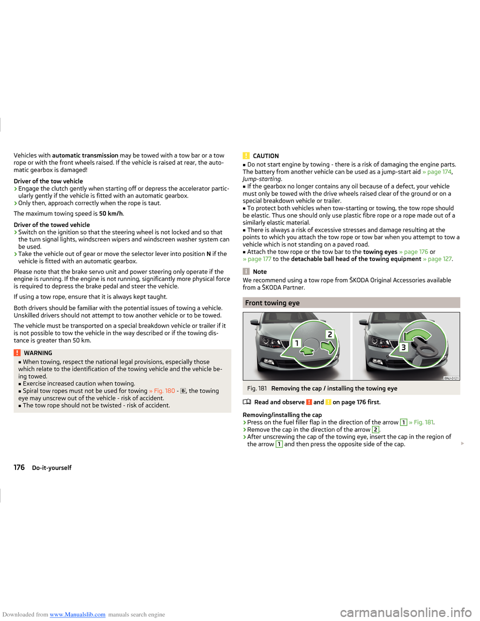
Fig. 181
Removing the cap / installing the towing eye
Read and observe
and on page 176 first.
Removing/installing the cap
›
Press on the fuel filler flap in the direction of the arrow
1
» Fig. 181 .
›
Remove the cap in the direction of the arrow
2
.
›
After unscrewing the cap of the towing eye, insert the cap in the region of
the arrow
1
and then press the opposite side of the cap.
176Do-it-yourself
Page 187 of 216
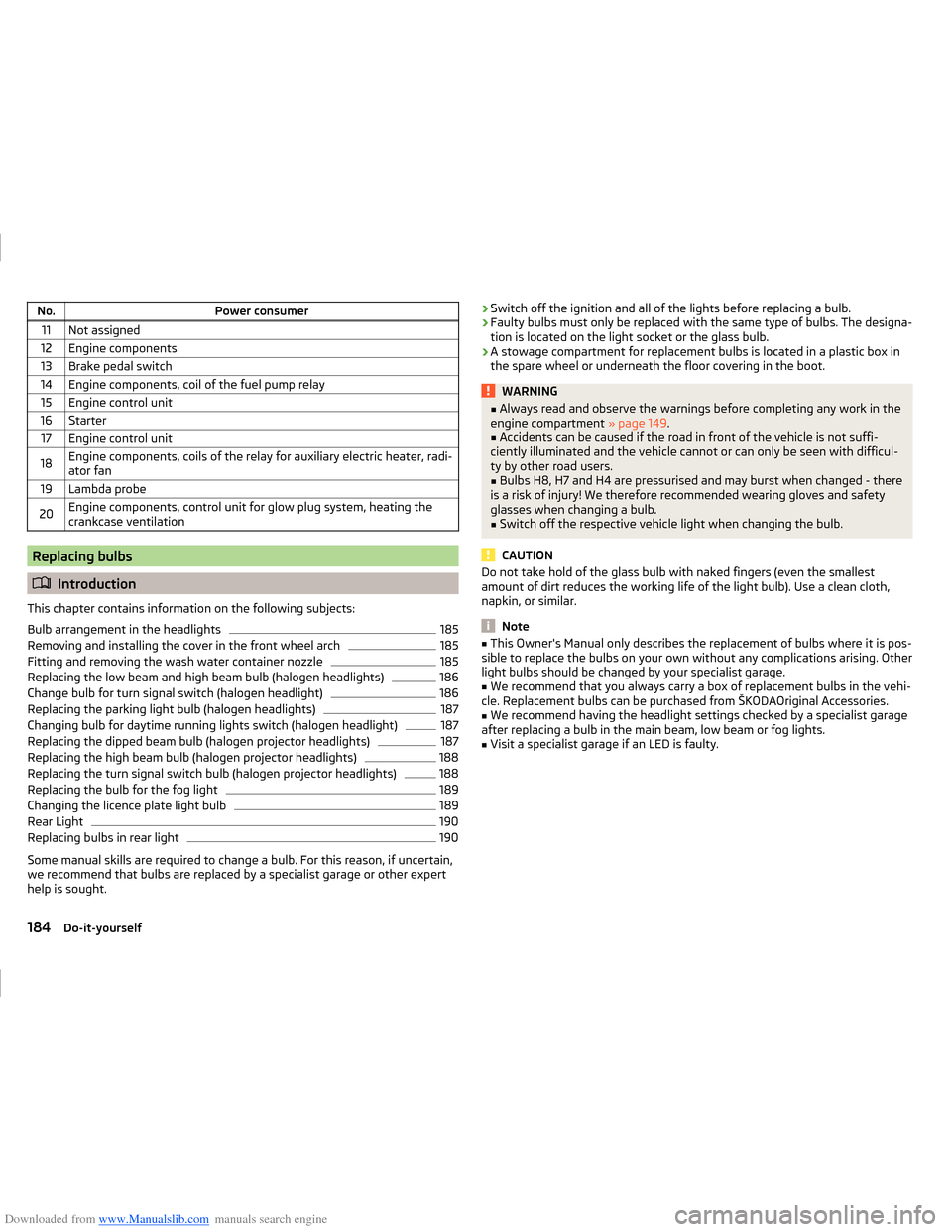
Downloaded from www.Manualslib.com manuals search engine No.Power consumer11Not assigned12Engine components13Brake pedal switch14Engine components, coil of the fuel pump relay15Engine control unit16Starter17Engine control unit18Engine components, coils of the relay for auxiliary electric heater, radi-
ator fan19Lambda probe20Engine components, control unit for glow plug system, heating the
crankcase ventilation
Replacing bulbs
Introduction
This chapter contains information on the following subjects:
Bulb arrangement in the headlights
185
Removing and installing the cover in the front wheel arch
185
Fitting and removing the wash water container nozzle
185
Replacing the low beam and high beam bulb (halogen headlights)
186
Change bulb for turn signal switch (halogen headlight)
186
Replacing the parking light bulb (halogen headlights)
187
Changing bulb for daytime running lights switch (halogen headlight)
187
Replacing the dipped beam bulb (halogen projector headlights)
187
Replacing the high beam bulb (halogen projector headlights)
188
Replacing the turn signal switch bulb (halogen projector headlights)
188
Replacing the bulb for the fog light
189
Changing the licence plate light bulb
189
Rear Light
190
Replacing bulbs in rear light
190
Some manual skills are required to change a bulb. For this reason, if uncertain,
we recommend that bulbs are replaced by a specialist garage or other expert
help is sought.
› Switch off the ignition and all of the lights before replacing a bulb.
› Faulty bulbs must only be replaced with the same type of bulbs. The designa-
tion is located on the light socket or the glass bulb.
› A stowage compartment for replacement bulbs is located in a plastic box in
the spare wheel or underneath the floor covering in the boot.WARNING■ Always read and observe the warnings before completing any work in the
engine compartment » page 149.■
Accidents can be caused if the road in front of the vehicle is not suffi-
ciently illuminated and the vehicle cannot or can only be seen with difficul-
ty by other road users.
■
Bulbs H8, H7 and H4 are pressurised and may burst when changed - there
is a risk of injury! We therefore recommended wearing gloves and safety
glasses when changing a bulb.
■
Switch off the respective vehicle light when changing the bulb.
CAUTION
Do not take hold of the glass bulb with naked fingers (even the smallest
amount of dirt reduces the working life of the light bulb). Use a clean cloth,
napkin, or similar.
Note
■ This Owner's Manual only describes the replacement of bulbs where it is pos-
sible to replace the bulbs on your own without any complications arising. Other
light bulbs should be changed by your specialist garage.■
We recommend that you always carry a box of replacement bulbs in the vehi-
cle. Replacement bulbs can be purchased from ŠKODAOriginal Accessories.
■
We recommend having the headlight settings checked by a specialist garage
after replacing a bulb in the main beam, low beam or fog lights.
■
Visit a specialist garage if an LED is faulty.
184Do-it-yourself
Page 188 of 216
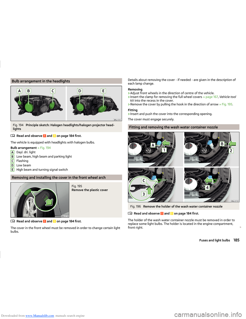
Downloaded from www.Manualslib.com manuals search engine Bulb arrangement in the headlightsFig. 194
Principle sketch: Halogen headlights/halogen projector head-
lights
Read and observe
and on page 184 first.
The vehicle is equipped with headlights with halogen bulbs.
Bulb arrangement » Fig. 194
Dayl. dri. light
Low beam, high beam and parking light
Flashing
Low beam
High beam and turning signal switch
Removing and installing the cover in the front wheel arch
Fig. 195
Remove the plastic cover
Read and observe and on page 184 first.
The cover in the front wheel must be removed in order to change certain light
bulbs.
ABCDEDetails about removing the cover - if needed - are given in the description of
each lamp change.
Removing›
Adjust front wheels in the direction of centre of the vehicle.
›
Insert the clamp for removing the full wheel covers » page 167, Vehicle tool
kit into the recess in the cover.
›
Remove the cover by pulling the hook in the direction of arrow » Fig. 195.
Fitting
›
Insert and push the cover into the corresponding opening.
The cover must engage securely.
Fitting and removing the wash water container nozzle
Fig. 196
Remove the holder of the wash water container nozzle
Read and observe
and on page 184 first.
The holder of the wash water container nozzle must be removed in order to
replace some light bulbs. The holder is located in the engine compartment,
front right.
185Fuses and light bulbs