seats SKODA FABIA 2014 3.G / NJ Operating Instruction Manual
[x] Cancel search | Manufacturer: SKODA, Model Year: 2014, Model line: FABIA, Model: SKODA FABIA 2014 3.G / NJPages: 216, PDF Size: 30.9 MB
Page 77 of 216
Downloaded from www.Manualslib.com manuals search engine Inserting›Insert the wire clips in the direction of arrow 3 » Fig. 64 and insert into the
brackets.
Folding backwards›
Fold the backrest in the direction of the arrow
4
» Fig. 65 .
›
Place the rear seat on the eyelets
A
, so that the eyelets
A
engage in the
recesses in the plastic caps for
B
» .
WARNINGThe rear seat must not be pulled in under the eyelets A when folding for-
wards - this would mean the rear seat could not be secured correctly.
CAUTION
The rear seat must not be pulled in under the eyelets A when being folded
back - there is a risk of damaging the rear seat.Transporting and practical equipment
Useful equipment
Introduction
This chapter contains information on the following subjects:
Car park ticket holder
75
Storage compartments in the doors
75
Storage compartment on the side of front seat
75
Storage compartment in the front centre console
76
Coin and credit card holder
76
Storage compartment on the dash panel
76
Cup holders
76
Cigarette lighter
77
Ashtray
77
12-volt power outlet
78
Waste container
78
Multimedia holder
79
Storage compartment in the front arm rest
79
Glasses compartment
80
Storage compartment on the front passenger side
80
Storage compartment under the front seat
81
Clothes hook
81
Storage pockets on the front seats
81
Net pockets on the front seat rest
82
Storage compartment in the rear centre console
82
AUX and USB inputs
82WARNING■ Do not place anything on the dash panel. These objects might slide or fall
down while you are driving (under acceleration or when cornering) and
could distract you from the traffic - risk of accident.■
Make sure that no objects from the centre console or from other storage
compartments can get into the driver's footwell while you are driving. You
would not be able to brake, operate the clutch pedal or accelerate - danger
of causing an accident!
74Operation
Page 84 of 216

Downloaded from www.Manualslib.com manuals search engine Storage compartment under the front seatFig. 81
Opening the storage compart-
ment
Read and observe on page 74 first.
Opening
›
Pull the handle to position
1
» Fig. 81 in the direction of the arrow.
›
Remove the wiper blade in the direction of the arrow
2
.
Closing
›
Grip the compartment by the handle and close in the opposite direction to
that of the arrow
2
» Fig. 81 .
›
Keep hold of the handle until the compartment is closed.
The storage compartment is designed for storing small objects of up to 1.5 kg.
in weight.
WARNINGThe storage compartment must always be closed when driving for safety
reasons.
Clothes hook
Read and observe
on page 74 first.
The clothes hooks are located on the handles of the headliner above each of
the rear doors.
The maximum permissible load of the hooks is 2 kg.
WARNING■ Only hang light items of clothing on the hooks. Never leave any heavy or
sharp-edged objects in the pockets of the items of clothing.■
Do not use clothes hangers for hanging up items of clothing; this may re-
duce the effectiveness of the head airbags.
■
Ensure that any clothes hanging from the hooks do not impair your vision
to the rear.
Storage pockets on the front seats
Fig. 82
Map pockets
Read and observe on page 74 first.
The Storage pockets » Fig. 82 are intended for the Storage e.g. of maps, maga-
zines, etc.
WARNINGNever put heavy items in the map pockets – risk of injury.
CAUTION
Never put large objects into the map pockets, e.g. bottles or objects with sharp
edges - risk of damaging the pockets and seat coverings.81Transporting and practical equipment
Page 86 of 216
Downloaded from www.Manualslib.com manuals search engine Luggage compartment
Introduction
This chapter contains information on the following subjects:
Fastening elements
84
Fixing nets
84
Hooks
85
Storage compartments in the luggage compartment
85
Luggage compartment cover
86
Other positions of the luggage compartment cover
86
Roll-up cover
87
Storage compartments under the floor
87
Cargo element
88
Flexible storage compartment
88
Class N1 vehicles
88
Please observe the following for the purpose of maintaining good handling
characteristics of your vehicle:
›
Distribute loads as evenly as possible.
›
Place heavy objects as far forward as possible.
›
Attach the items of luggage to the lashing eyes or by using the fixing nets
» page 84 .
In the event of an accident, even small and light objects gain so much kinetic energy that they can cause severe injuries.
The magnitude of the kinetic energy is dependent on the speed at which the
vehicle is travelling and the weight of the object.
Example: In the event of a frontal collision at a speed of 50 km/h, an object
weighing 4.5 kg produces energy corresponding to 20 times its own weight.
This means that it results in a weight of approx. 90 kg “ ”.
Luggage compartment light
The warning light turns on when tailgate is opened.
The warning light turns off when the tailgate is closed.
If the boot lid is open and the ignition switched off, the light will extinguish
automatically after around 10 minutes.
WARNING■ Always store transported objects in the boot and attach them to the lash-
ing eyes.■
Loose objects can be thrown forward during a sudden manoeuvre or in
case of an accident and can injure the occupants or other road users.
■
Loose objects could hit a deployed airbag and injure occupants – risk to
life!
■
Please note that the handling properties of the vehicle may be affected
when transporting heavy objects as the centre of gravity can be shifted –
risk of accident. The speed and style of driving must be adjusted according-
ly.
■
If the items of luggage or objects are attached to the lashing eyes with
unsuitable or damaged lashing straps, injuries can occur in the event of
braking manoeuvres or accidents. To prevent items of luggage from moving
around, always use suitable lashing straps that are firmly attached to the
lashing eyes.
■
Items carried in the luggage compartment must be stowed in such a way
that no objects are able to slip forward under sudden driving manoeuvres
or braking – risk of injury.
■
When transporting objects in the luggage compartment that has been en-
larged by folding the rear seats forward, ensure the safety of the passen-
gers transported on the other rear seats » page 10.
■
Do not drive with the luggage compartment lid open or unlatched, other-
wise exhaust gases may get into the interior of the vehicle – risk of poison-
ing!
■
Do not exceed the permissible axle loads and permissible gross weight of
the vehicle – risk of accident!
■
Do not transport people in the boot!
CAUTION
■ Please ensure that the heating elements for the rear window heater are not
damaged as a result of abrasive objects.■
Tyre pressure must be adjusted to the load » page 161.
83Transporting and practical equipment
Page 89 of 216
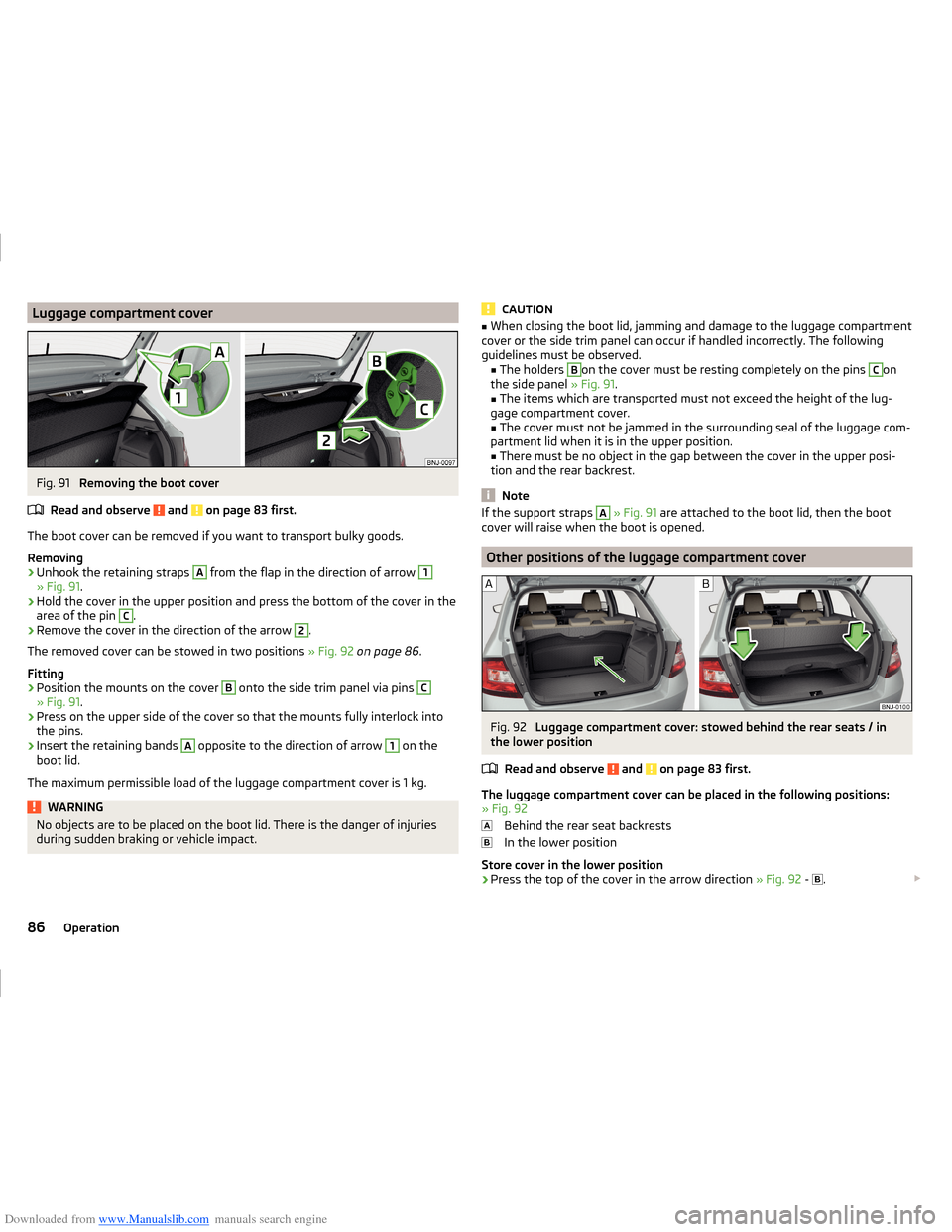
Downloaded from www.Manualslib.com manuals search engine Luggage compartment coverFig. 91
Removing the boot cover
Read and observe
and on page 83 first.
The boot cover can be removed if you want to transport bulky goods.
Removing
›
Unhook the retaining straps
A
from the flap in the direction of arrow
1
» Fig. 91 .
›
Hold the cover in the upper position and press the bottom of the cover in the
area of the pin
C
.
›
Remove the cover in the direction of the arrow
2
.
The removed cover can be stowed in two positions » Fig. 92 on page 86 .
Fitting
›
Position the mounts on the cover
B
onto the side trim panel via pins
C
» Fig. 91 .
›
Press on the upper side of the cover so that the mounts fully interlock into
the pins.
›
Insert the retaining bands
A
opposite to the direction of arrow
1
on the
boot lid.
The maximum permissible load of the luggage compartment cover is 1 kg.
WARNINGNo objects are to be placed on the boot lid. There is the danger of injuries
during sudden braking or vehicle impact.CAUTION■ When closing the boot lid, jamming and damage to the luggage compartment
cover or the side trim panel can occur if handled incorrectly. The following
guidelines must be observed. ■ The holders B
on the cover must be resting completely on the pins
C
on
the side panel » Fig. 91.
■ The items which are transported must not exceed the height of the lug-
gage compartment cover. ■ The cover must not be jammed in the surrounding seal of the luggage com-
partment lid when it is in the upper position.
■ There must be no object in the gap between the cover in the upper posi-
tion and the rear backrest.
Note
If the support straps A » Fig. 91 are attached to the boot lid, then the boot
cover will raise when the boot is opened.
Other positions of the luggage compartment cover
Fig. 92
Luggage compartment cover: stowed behind the rear seats / in
the lower position
Read and observe
and on page 83 first.
The luggage compartment cover can be placed in the following positions:
» Fig. 92
Behind the rear seat backrests
In the lower position
Store cover in the lower position
›
Press the top of the cover in the arrow direction » Fig. 92 -
.
86Operation
Page 91 of 216
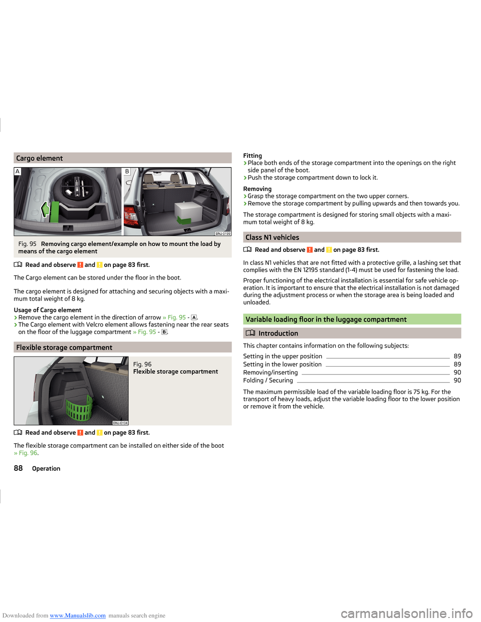
Downloaded from www.Manualslib.com manuals search engine Cargo elementFig. 95
Removing cargo element/example on how to mount the load by
means of the cargo element
Read and observe
and on page 83 first.
The Cargo element can be stored under the floor in the boot.
The cargo element is designed for attaching and securing objects with a maxi-
mum total weight of 8 kg.
Usage of Cargo element
›
Remove the cargo element in the direction of arrow » Fig. 95 -
.
›
The Cargo element with Velcro element allows fastening near the rear seats
on the floor of the luggage compartment » Fig. 95 -
.
Flexible storage compartment
Fig. 96
Flexible storage compartment
Read and observe and on page 83 first.
The flexible storage compartment can be installed on either side of the boot
» Fig. 96 .
Fitting›Place both ends of the storage compartment into the openings on the right
side panel of the boot.›
Push the storage compartment down to lock it.
Removing
›
Grasp the storage compartment on the two upper corners.
›
Remove the storage compartment by pulling upwards and then towards you.
The storage compartment is designed for storing small objects with a maxi-
mum total weight of 8 kg.
Class N1 vehicles
Read and observe
and on page 83 first.
In class N1 vehicles that are not fitted with a protective grille, a lashing set that
complies with the EN 12195 standard (1-4) must be used for fastening the load.
Proper functioning of the electrical installation is essential for safe vehicle op-
eration. It is important to ensure that the electrical installation is not damaged
during the adjustment process or when the storage area is being loaded and
unloaded.
Variable loading floor in the luggage compartment
Introduction
This chapter contains information on the following subjects:
Setting in the upper position
89
Setting in the lower position
89
Removing/inserting
90
Folding / Securing
90
The maximum permissible load of the variable loading floor is 75 kg. For the
transport of heavy loads, adjust the variable loading floor to the lower position
or remove it from the vehicle.
88Operation
Page 96 of 216
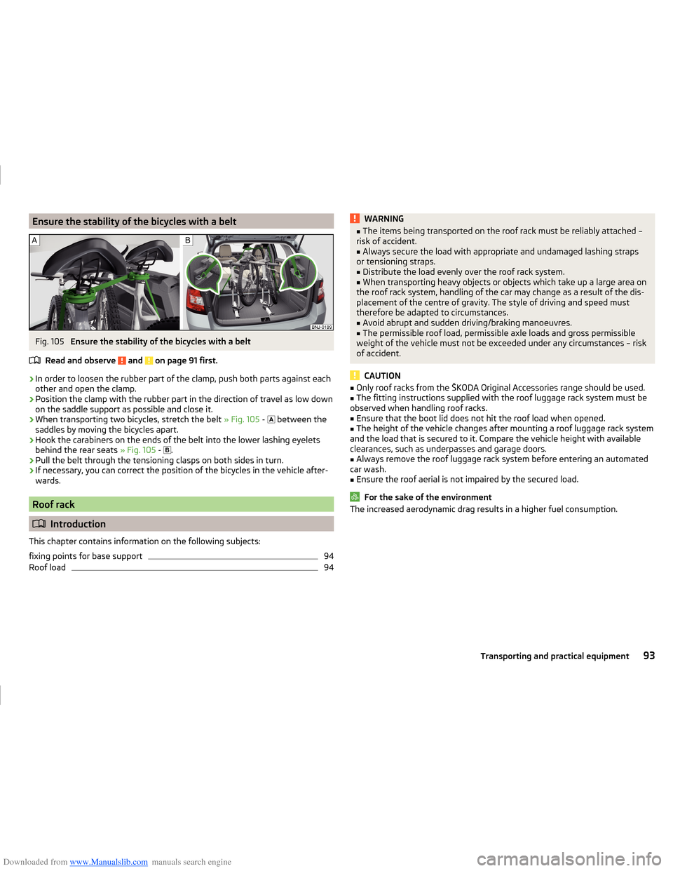
Downloaded from www.Manualslib.com manuals search engine Ensure the stability of the bicycles with a beltFig. 105
Ensure the stability of the bicycles with a belt
Read and observe
and on page 91 first.
›
In order to loosen the rubber part of the clamp, push both parts against each
other and open the clamp.
›
Position the clamp with the rubber part in the direction of travel as low down
on the saddle support as possible and close it.
›
When transporting two bicycles, stretch the belt » Fig. 105 -
between the
saddles by moving the bicycles apart.
›
Hook the carabiners on the ends of the belt into the lower lashing eyelets
behind the rear seats » Fig. 105 -
.
›
Pull the belt through the tensioning clasps on both sides in turn.
›
If necessary, you can correct the position of the bicycles in the vehicle after-
wards.
Roof rack
Introduction
This chapter contains information on the following subjects:
fixing points for base support
94
Roof load
94WARNING■ The items being transported on the roof rack must be reliably attached –
risk of accident.■
Always secure the load with appropriate and undamaged lashing straps
or tensioning straps.
■
Distribute the load evenly over the roof rack system.
■
When transporting heavy objects or objects which take up a large area on
the roof rack system, handling of the car may change as a result of the dis-
placement of the centre of gravity. The style of driving and speed must
therefore be adapted to circumstances.
■
Avoid abrupt and sudden driving/braking manoeuvres.
■
The permissible roof load, permissible axle loads and gross permissible
weight of the vehicle must not be exceeded under any circumstances – risk
of accident.
CAUTION
■ Only roof racks from the ŠKODA Original Accessories range should be used.■The fitting instructions supplied with the roof luggage rack system must be
observed when handling roof racks.■
Ensure that the boot lid does not hit the roof load when opened.
■
The height of the vehicle changes after mounting a roof luggage rack system
and the load that is secured to it. Compare the vehicle height with available
clearances, such as underpasses and garage doors.
■
Always remove the roof luggage rack system before entering an automated
car wash.
■
Ensure the roof aerial is not impaired by the secured load.
For the sake of the environment
The increased aerodynamic drag results in a higher fuel consumption.93Transporting and practical equipment
Page 149 of 216
Downloaded from www.Manualslib.com manuals search engine Alcantara®
Dust and dirt in pores, creases and seams may chafe and damage the surface.
Therefore, they must be removed regularly at short intervals with a cloth or
vacuum cleaner.
Minor changes in colour caused by use are normal.
CAUTION
■ For Alcantara ®
seat covers, do not use any solvents, floor wax, shoe cream,
stain remover, leather cleaners or similar agents.■
Avoid leaving the vehicle in bright sunlight for long periods of time in order
to stop the artificial leather, materials or Alcantara ®
from bleaching. During ex-
tended periods of standing outdoors, protect artificial leather, fabrics or Alcan-
tara ®
by covering.
■
Some clothing materials, such as dark denim, do not have sufficient colour
fastness. This can cause damage or clearly visible discolouration to seat covers
even when treated correctly. This is particularly true for light-coloured uphols-
tery. This is not a defect in the seat cover, but poor colour fastness of the
clothing textiles.
Seat covers
Read and observe
and on page 144 first.
Electrically heated seats
Use a specific cleaning agent such as dry foam or similar to clean the covers.
»
.
Seats without seat heating
Thoroughly vacuum the seat covers with a vacuum cleaner before cleaning.
Clean the seat covers with a damp cloth or cleaning agents particularly formu-
lated for them.
Compressed areas created on the fabrics by everyday use can be removed by
brushing against the nap with a lightly moistened brush.
Always treat all parts of the upholstery so that no visible boundaries are cre-
ated. Then leave the seat to dry completely.
CAUTION
■ Do not clean the covers of electrically heated seats either with water or with
other liquids - there is a risk of damaging the seat heating system.■
Regularly vacuum dust from the seat covers using a vacuum cleaner.
■ Electrically heated seats must not be dried after cleaning by switching on the
heater.■
Do not sit on wet seats - there is a risk of stretching the upholstery.
■
Always clean the seats “from seam to seam”.
Safety belts
Read and observe
and on page 144 first.
Wash dirty seat belts with a mild, soapy solution.
Remove dirt with a soft brush.
WARNING■ The seat belts must not be removed for cleaning.■Never clean the seat belts chemically as chemical cleaning products could
destroy the fabric.■
The seat belts must not be allowed to come into contact with corrosive
liquids (such as acids etc.).
■
Inertia reel belts must be completely dried before being rolled up.
146General Maintenance
Page 185 of 216
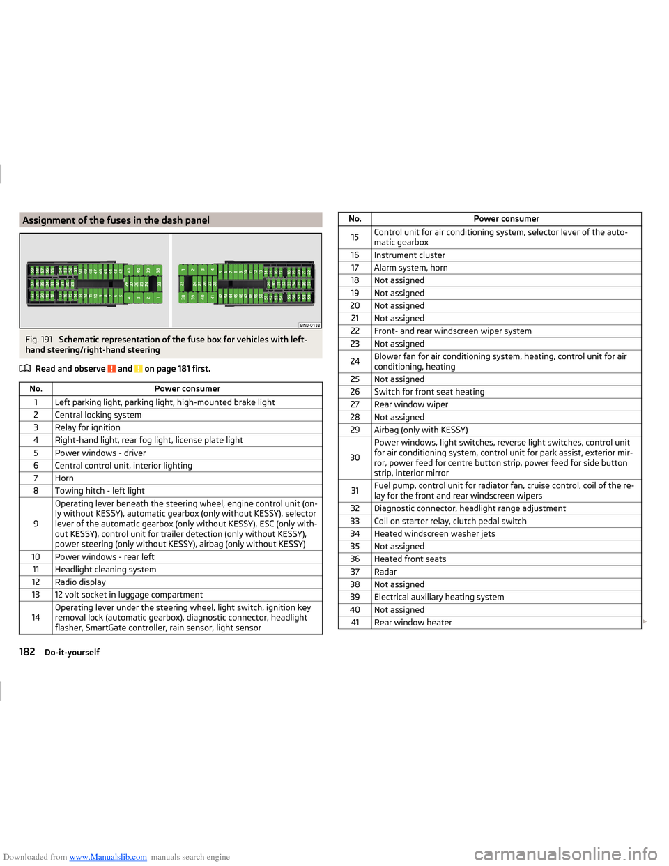
Downloaded from www.Manualslib.com manuals search engine Assignment of the fuses in the dash panelFig. 191
Schematic representation of the fuse box for vehicles with left-
hand steering/right-hand steering
Read and observe
and on page 181 first.
No.Power consumer1Left parking light, parking light, high-mounted brake light2Central locking system3Relay for ignition4Right-hand light, rear fog light, license plate light5Power windows - driver6Central control unit, interior lighting7Horn8Towing hitch - left light
9
Operating lever beneath the steering wheel, engine control unit (on-
ly without KESSY), automatic gearbox (only without KESSY), selector
lever of the automatic gearbox (only without KESSY), ESC (only with-
out KESSY), control unit for trailer detection (only without KESSY),
power steering (only without KESSY), airbag (only without KESSY)10Power windows - rear left11Headlight cleaning system12Radio display1312 volt socket in luggage compartment14Operating lever under the steering wheel, light switch, ignition key
removal lock (automatic gearbox), diagnostic connector, headlight
flasher, SmartGate controller, rain sensor, light sensorNo.Power consumer15Control unit for air conditioning system, selector lever of the auto-
matic gearbox16Instrument cluster17Alarm system, horn18Not assigned19Not assigned20Not assigned21Not assigned22Front- and rear windscreen wiper system23Not assigned24Blower fan for air conditioning system, heating, control unit for air
conditioning, heating25Not assigned26Switch for front seat heating27Rear window wiper28Not assigned29Airbag (only with KESSY)
30
Power windows, light switches, reverse light switches, control unit
for air conditioning system, control unit for park assist, exterior mir-
ror, power feed for centre button strip, power feed for side button
strip, interior mirror31Fuel pump, control unit for radiator fan, cruise control, coil of the re-
lay for the front and rear windscreen wipers32Diagnostic connector, headlight range adjustment33Coil on starter relay, clutch pedal switch34Heated windscreen washer jets35Not assigned36Heated front seats37Radar38Not assigned39Electrical auxiliary heating system40Not assigned41Rear window heater 182Do-it-yourself
Page 186 of 216
Downloaded from www.Manualslib.com manuals search engine No.Power consumer42Power windows - front passenger43Towing hitch - contact in the socket44Cigarette lighter, 12-volt power socket45Power windows - rear right46Front and rear window washer, operating lever under the steering
wheel47Towing hitch - contact in the socket48Towing hitch - right light49Control unit for fuel pump50Radio51Heating of the external mirror52KESSY control unit53KESSY steering lock54Not assigned55Heated front seats56Not assigned57Not assigned58Not assigned59Not assigned
Fuses in the engine compartment
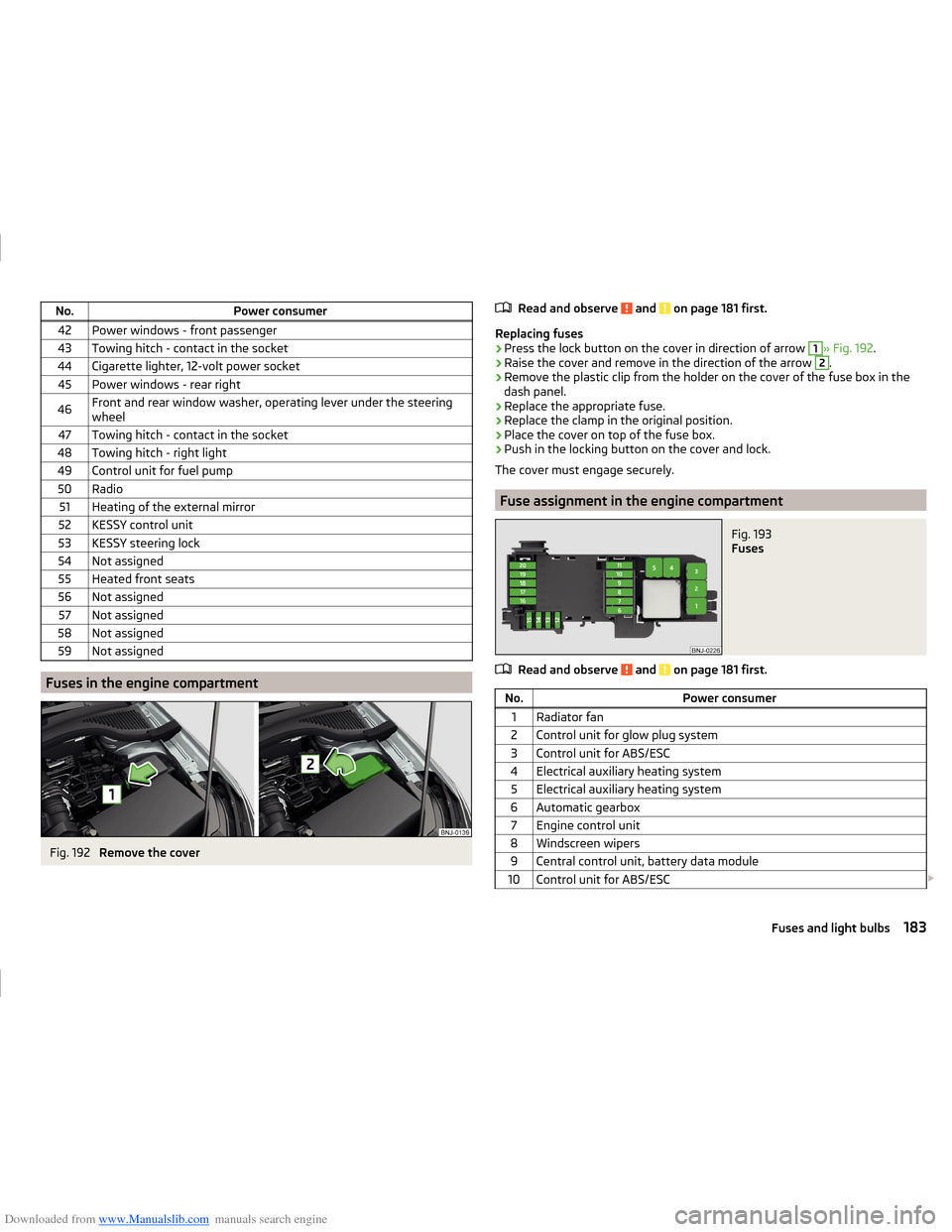
Fig. 192
Remove the cover
Read and observe and on page 181 first.
Replacing fuses
›
Press the lock button on the cover in direction of arrow
1
» Fig. 192 .
›
Raise the cover and remove in the direction of the arrow
2
.
›
Remove the plastic clip from the holder on the cover of the fuse box in the
dash panel.
›
Replace the appropriate fuse.
›
Replace the clamp in the original position.
›
Place the cover on top of the fuse box.
›
Push in the locking button on the cover and lock.
The cover must engage securely.
Fuse assignment in the engine compartment
Fig. 193
Fuses
Read and observe and on page 181 first.
No.Power consumer1Radiator fan2Control unit for glow plug system3Control unit for ABS/ESC4Electrical auxiliary heating system5Electrical auxiliary heating system6Automatic gearbox7Engine control unit8Windscreen wipers9Central control unit, battery data module10Control unit for ABS/ESC 183Fuses and light bulbs
Page 203 of 216
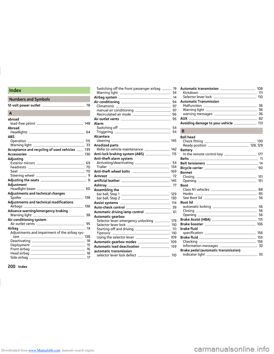
Downloaded from www.Manualslib.com manuals search engine Index
Numbers and Symbols
12-volt power outlet
78
A
abroad lead-free petrol
148
Abroad Headlights
64
ABS Operation
115
Warning light33
Acceptance and recycling of used vehicles139
Accessories136
Adjusting Exterior mirrors
69
headrests70
Seat70
Steering wheel9
Adjusting the seats8
Adjustment Headlight beam
60
Adjustments and technical changes Spoiler
138
Adjustments and technical modifications Airbags
138
Advance warning/emergency braking Warning light
38
Air-conditioning system Air outlet vents
95
Airbag14
Adjustments and impairment of the airbag sys- tem
138
Deactivating18
Deployment15
Front airbag16
Head airbag18
Side airbag17
Switching off the front passenger airbag19
Warning light34
Airbag system14
Air conditioning94
Climatronic97
manual air conditioning97
Recirculated air mode96
Air outlet vents95
Alarm Switching off
54
Triggering54
Alcantara cleaning
145
Anodized parts Refer to vehicle maintenance
142
Anti-lock braking system (ABS)115
Anti-theft alarm system Activating/deactivating
54
Trailer134
Anti-theft wheel bolts 169
Armrest72
artificial leather145
Ashtray77
Assembling the bar ball, Step 1
129
bar ball, Step 2130
Assist systems114
Auto-check control39
Automatic driving lamp control61
Automatic gearbox Selector lever-emergency unlocking
179
Selector lever lock110
Starting-off and driving111
Tiptronic110
Using the selector lever109
Automatic gearbox modes109
Automatic load deactivation159
automatic transmission selector lever lock defect
110
Automatic transmission108
Kickdown111
Selector lever lock110
Automatic Transmission Malfunction
36
Warning light36
warning messages36
AUX82
Avoiding damage to your vehicle113
B
Ball head Check fitting
130
Ready position128, 129
Battery In the remote control key
177
Belts11
Belt tensioners14
Bicycle carrier90
Bonnet Closing
151
Opening151
Boot Class N1 vehicles
88
Hooks85
See Boot lid56
Boot lid automatic locking
56
Closing56
Opening56
Brake Assist (HBA)115
Brake booster106
brake fluid specification
156
Brake fluid155
Checking156
Information messages32
Brake pedal (automatic transmission) Indicator light
35
200Index