tow SKODA FABIA 2014 3.G / NJ Operating Instruction Manual
[x] Cancel search | Manufacturer: SKODA, Model Year: 2014, Model line: FABIA, Model: SKODA FABIA 2014 3.G / NJPages: 216, PDF Size: 30.9 MB
Page 109 of 216
Downloaded from www.Manualslib.com manuals search engine A system error is present. Seek help from a specialist garage.
Brakes and parking
Introduction
This chapter contains information on the following subjects:
Information for braking
106
Handbrake
107
Parking
107WARNING■ Greater physical effort is required for braking when the engine is switch-
ed off – risk of accident.■
The clutch pedal must be depressed when braking on a vehicle with man-
ual transmission, when the vehicle is in gear and at low revs. Otherwise,
the functionality of the brake system may be impaired – risk of accident!
■
When leaving the vehicle never leave persons leave unattended in the
vehicle who could release the brake. The vehicle might then move off – risk
of accident.
■
Observe the recommendations on the new brake pads » page 111.
CAUTION
Never let the brakes slip with light pressure on the pedal if braking is not nec-
essary. This causes the brakes to overheat and can also result in a longer brak-
ing distance and excessive wear.
Information for braking
Read and observe
and on page 106 first.
Wear-and-tear
The wear of the brake pads is dependent on the operating conditions and driv-
ing style.
The brake pads wear more quickly if a lot of journeys are completed in towns
and over short distances or if a very sporty style of driving is adopted.
Under these severe conditions , the thickness of the brake pads must also be
checked by a specialist garage between services.
Wet roads or road salt
The performance of the brakes can be delayed as the brake discs and brake
pads may be moist or have a coating of ice or layer of salt on them in winter.
The brakes are cleaned and dried by applying the brakes several times »
.
Corrosion
Corrosion on the brake discs and dirt on the brake pads occur if the vehicle has
been parked for a long period and if you do not make much use of the braking
system. The brakes are cleaned by applying the brakes several times »
.
Long or steep slopes
Before travelling a long distance with a steep gradient, reduce speed and shift
into the next lowest gear. As a result, the braking effect of the engine will be
used, reducing the load on the brakes. Any additional braking should be com-
pleted intermittently, not continuously.
Emergency brake display
If the brakes are applied in full and the control unit for the braking system con-
siders the situation to be dangerous for the following traffic, the brake light
flashes automatically.
After the speed was reduced below around 10 km/h or the vehicle was stop-
ped, the brake light stops flashing and the hazard warning light system
switches on. The hazard warning light system is switched off automatically af- ter accelerating or driving off again.
Fault in the brake system
If it is found that the braking distance has suddenly become longer and that
the brake pedal can be depressed further, there may be a fault in the brake
system.
Visit a specialist garage immediately and adjust your style of driving appropri-
ately as you will not know how great the damage is.
Low brake fluid level
An insufficient level of brake fluid may result in problems in the brake system.
The fluid level is monitored electronically » page 32,
Brake system
.
Brake booster
The brake booster increases the pressure generated with the brake pedal. The brake booster only operates when the engine is running.
106Driving
Page 113 of 216
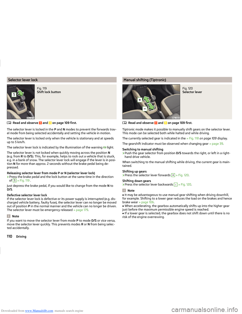
Downloaded from www.Manualslib.com manuals search engine Selector lever lockFig. 119
Shift lock button
Read and observe and on page 109 first.
The selector lever is locked in the P and N modes to prevent the forwards trav-
el mode from being selected accidentally and setting the vehicle in motion.
The selector lever is locked only when the vehicle is stationary and at speeds
up to 5 km/h.
The selector lever lock is indicated by the illumination of the warning light.
The selector lever is not locked when quickly moving across the position N
(e.g. from R to D/S ). This, for example, helps to rock out a vehicle that is stuck,
e.g. in a bank of snow. The selector lever lock will engage if the lever is in posi-
tion N for more than approx. 2 seconds without the brake pedal being de-
pressed.
Releasing selector lever from mode P or N (selector lever lock)
›
Press the brake pedal and the lock button at the same time in the direction
of
1
» Fig. 119 .
Just depress the brake pedal, if you would like to change from the mode N to
D/S .
Defective selector lever lock
If the selector lever lock is defective or its power supply is interrupted (e.g. dis-
charged vehicle battery, faulty fuse), the selector lever can no longer be moved
out of position P in the normal manner and the vehicle can no longer be driven.
The selector lever must be emergency released » page 179.
Note
If you want to move the selector lever from mode P to mode D/S or vice versa,
move the selector lever quickly. This prevents modes R or N from being selec-
ted accidentally.Manual shifting (Tiptronic)Fig. 120
Selector lever
Read and observe and on page 109 first.
Tiptronic mode makes it possible to manually shift gears on the selector lever. This mode can be selected both while halted and while driving.
The currently selected gear is indicated in the » Fig. 118 on page 109 display.
The gearshift indicator must be observed when changing gear » page 39.
Switching to manual shifting
›
Push the gear selector from position D/S towards the right, or left in a right-
hand drive vehicle.
When switching to the manual shifting while driving, the current gear is main-
tained.
Shifting up gears
›
Press the selector lever forwards
+
» Fig. 120 .
Shifting down gears
›
Press the selector lever backwards
-
» Fig. 120 .
Note
■
It may be advantageous to use manual gear shifting when driving downhill,
for example. Shifting to a lower gear reduces the load on the brakes and hence
brake wear » page 106.■
When accelerating, the gearbox automatically shifts up into the higher gear
just before the maximum permissible engine speed is reached.
■
If a lower gear is selected, the gearbox does not shift down until there is no
risk of the engine overrevving.
110Driving
Page 120 of 216
Downloaded from www.Manualslib.com manuals search engine FunctionFig. 124
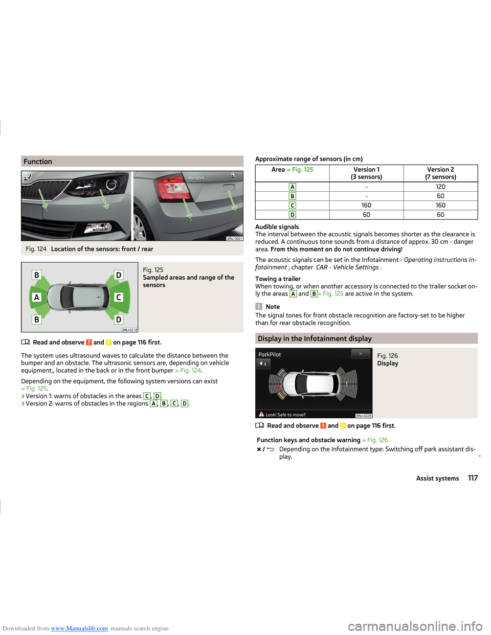
Location of the sensors: front / rear
Fig. 125
Sampled areas and range of the
sensors
Read and observe and on page 116 first.
The system uses ultrasound waves to calculate the distance between the
bumper and an obstacle. The ultrasonic sensors are, depending on vehicle
equipment,, located in the back or in the front bumper » Fig. 124.
Depending on the equipment, the following system versions can exist
» Fig. 125 .
› Version 1: warns of obstacles in the areas
C
,
D
.
› Version 2: warns of obstacles in the regions
A
,
B
,
C
,
D
.
Approximate range of sensors (in cm)Area
» Fig. 125Version 1
(3 sensors)Version 2
(7 sensors)A-120B-60C160160D6060
Audible signals
The interval between the acoustic signals becomes shorter as the clearance is
reduced. A continuous tone sounds from a distance of approx. 30 cm - danger
area. From this moment on do not continue driving!
The acoustic signals can be set in the Infotainment » Operating instructions In-
fotainment , chapter CAR - Vehicle Settings .
Towing a trailer
When towing, or when another accessory is connected to the trailer socket on-
ly the areas
A
and
B
» Fig. 125 are active in the system.
Note
The signal tones for front obstacle recognition are factory-set to be higher
than for rear obstacle recognition.
Display in the Infotainment display
Fig. 126
Display
Read and observe and on page 116 first.
Function keys and obstacle warning » Fig. 126 Depending on the Infotainment type: Switching off park assistant dis-
play. 117Assist systems
Page 127 of 216
Downloaded from www.Manualslib.com manuals search engine Automatic Braking
If the driver fails to respond to the acute warning, the system starts to apply
the brakes automatically with increasing stopping power in several stages.
Brake assist
If the driver brakes inadequate with an impending collision, the system auto-
matically increases braking force.
The braking assistance only occurs as long as the brake pedal is being firmly
pressed down.
Note
■ If an automatic brake intervention is triggered by the system, the pressure in
the brake system increases and the brake pedal cannot be operated with the
normal pedal stroke.■
The automatic braking interventions can be cancelled by pressing the accel-
erator pedal or by steering intervention.
Disable / enable
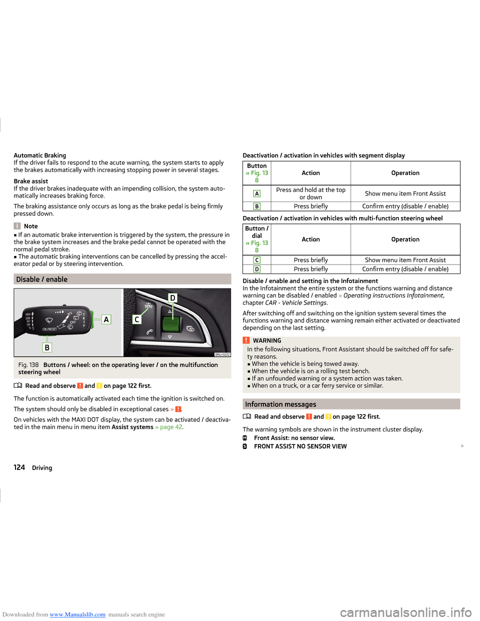
Fig. 138
Buttons / wheel: on the operating lever / on the multifunction
steering wheel
Read and observe
and on page 122 first.
The function is automatically activated each time the ignition is switched on.
The system should only be disabled in exceptional cases »
.
On vehicles with the MAXI DOT display, the system can be activated / deactiva-
ted in the main menu in menu item Assist systems » page 42 .
Deactivation / activation in vehicles with segment displayButton
» Fig. 13 8ActionOperation
APress and hold at the top or downShow menu item Front AssistBPress brieflyConfirm entry (disable / enable)
Deactivation / activation in vehicles with multi-function steering wheel
Button /dial
» Fig. 13 8
ActionOperation
CPress brieflyShow menu item Front AssistDPress brieflyConfirm entry (disable / enable)
Disable / enable and setting in the Infotainment
In the Infotainment the entire system or the functions warning and distance warning can be disabled / enabled » Operating instructions Infotainment ,
chapter CAR - Vehicle Settings .
After switching off and switching on the ignition system several times the
functions warning and distance warning remain either activated or deactivated
depending on the last setting.
WARNINGIn the following situations, Front Assistant should be switched off for safe-
ty reasons.■
When the vehicle is being towed away.
■
When the vehicle is on a rolling test bench.
■
If an unfounded warning or a system action was taken.
■
When on a truck, or a car ferry service or similar.
Information messages
Read and observe
and on page 122 first.
The warning symbols are shown in the instrument cluster display. Front Assist: no sensor view.
FRONT ASSIST NO SENSOR VIEW
124Driving
Page 130 of 216
Downloaded from www.Manualslib.com manuals search engine Save tyre pressure values by pressing a buttonFig. 140
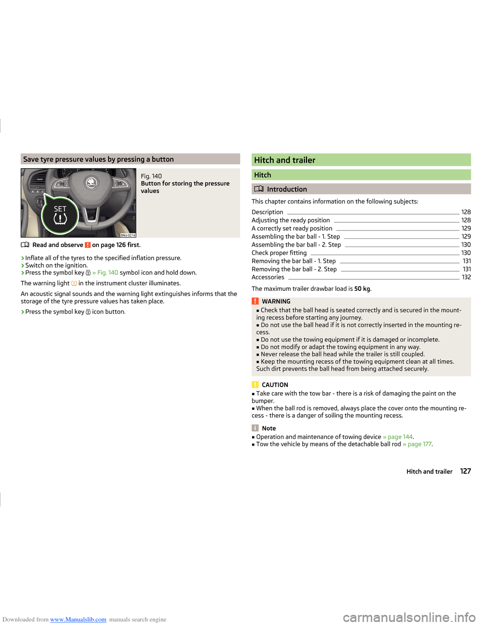
Button for storing the pressure
values
Read and observe on page 126 first.
›
Inflate all of the tyres to the specified inflation pressure.
›
Switch on the ignition.
›
Press the symbol key
» Fig. 140 symbol icon and hold down.
The warning light in the instrument cluster illuminates.
An acoustic signal sounds and the warning light extinguishes informs that the
storage of the tyre pressure values has taken place.
›
Press the symbol key icon button.
Hitch and trailer
Hitch
Introduction
This chapter contains information on the following subjects:
Description
128
Adjusting the ready position
128
A correctly set ready position
129
Assembling the bar ball - 1. Step
129
Assembling the bar ball - 2. Step
130
Check proper fitting
130
Removing the bar ball - 1. Step
131
Removing the bar ball - 2. Step
131
Accessories
132
The maximum trailer drawbar load is 50 kg.
WARNING■
Check that the ball head is seated correctly and is secured in the mount-
ing recess before starting any journey.■
Do not use the ball head if it is not correctly inserted in the mounting re-
cess.
■
Do not use the towing equipment if it is damaged or incomplete.
■
Do not modify or adapt the towing equipment in any way.
■
Never release the ball head while the trailer is still coupled.
■
Keep the mounting recess of the towing equipment clean at all times.
Such dirt prevents the ball head from being attached securely.
CAUTION
■ Take care with the tow bar - there is a risk of damaging the paint on the
bumper.■
When the ball rod is removed, always place the cover onto the mounting re-
cess - there is a danger of soiling the mounting recess.
Note
■ Operation and maintenance of towing device » page 144.■Tow the vehicle by means of the detachable ball rod » page 177.127Hitch and trailer
Page 131 of 216
Downloaded from www.Manualslib.com manuals search engine DescriptionFig. 141
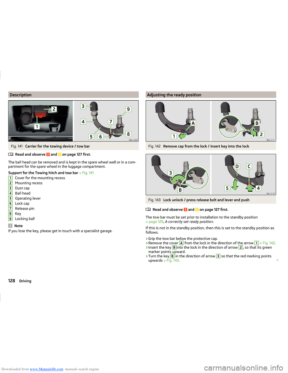
Carrier for the towing device / tow bar
Read and observe
and on page 127 first.
The ball head can be removed and is kept in the spare wheel well or in a com-
partment for the spare wheel in the luggage compartment.
Support for the Towing hitch and tow bar » Fig. 141
Cover for the mounting recess
Mounting recess
Dust cap
Ball head
Operating lever
Lock cap
Release pin
Key
Locking ball
Note
If you lose the key, please get in touch with a specialist garage.123456789Adjusting the ready positionFig. 142
Remove cap from the lock / insert key into the lock
Fig. 143
Lock unlock / press release bolt and lever and push
Read and observe
and on page 127 first.
The tow bar must be set prior to installation to the standby position
» page 129 , A correctly set ready position .
If this is not in the standby position, then this is set to the standby position as
follows.
›
Grip the tow bar below the protective cap.
›
Remove the cover
A
from the lock in the direction of the arrow
1
» Fig. 142 .
›
Insert the key
B
into the lock in the direction of arrow
2
, so that its green
marker points upward.
›
Turn the key
B
in the direction of arrow
3
so that the red marking points
upwards » Fig. 143 .
128Driving
Page 132 of 216
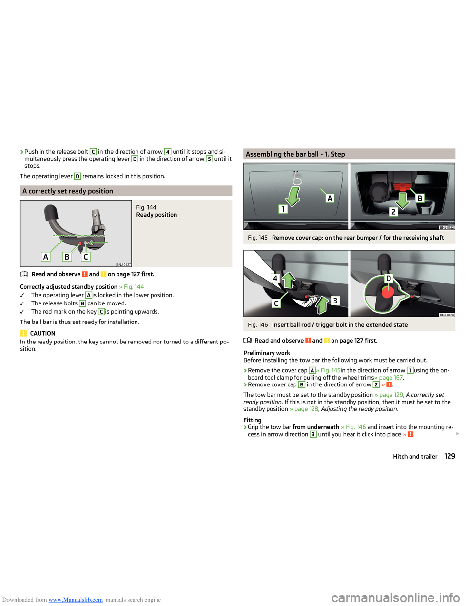
Downloaded from www.Manualslib.com manuals search engine ›Push in the release bolt C in the direction of arrow 4 until it stops and si-
multaneously press the operating lever D in the direction of arrow 5 until it
stops.
The operating lever D
remains locked in this position.
A correctly set ready position
Fig. 144
Ready position
Read and observe and on page 127 first.
Correctly adjusted standby position » Fig. 144
The operating lever
A
is locked in the lower position.
The release bolts
B
can be moved.
The red mark on the key
C
is pointing upwards.
The ball bar is thus set ready for installation.
CAUTION
In the ready position, the key cannot be removed nor turned to a different po-
sition.Assembling the bar ball - 1. StepFig. 145
Remove cover cap: on the rear bumper / for the receiving shaft
Fig. 146
Insert ball rod / trigger bolt in the extended state
Read and observe
and on page 127 first.
Preliminary work
Before installing the tow bar the following work must be carried out.
›
Remove the cover cap
A
» Fig. 145 in the direction of arrow
1
using the on-
board tool clamp for pulling off the wheel trims » page 167.
›
Remove cover cap
B
in the direction of arrow
2
» .
The tow bar must be set to the standby position » page 129, A correctly set
ready position . If this is not in the standby position, then it must be set to the
standby position » page 128, Adjusting the ready position .
Fitting
›
Grip the tow bar from underneath » Fig. 146 and insert into the mounting re-
cess in arrow direction
3
until you hear it click into place » .
129Hitch and trailer
Page 133 of 216
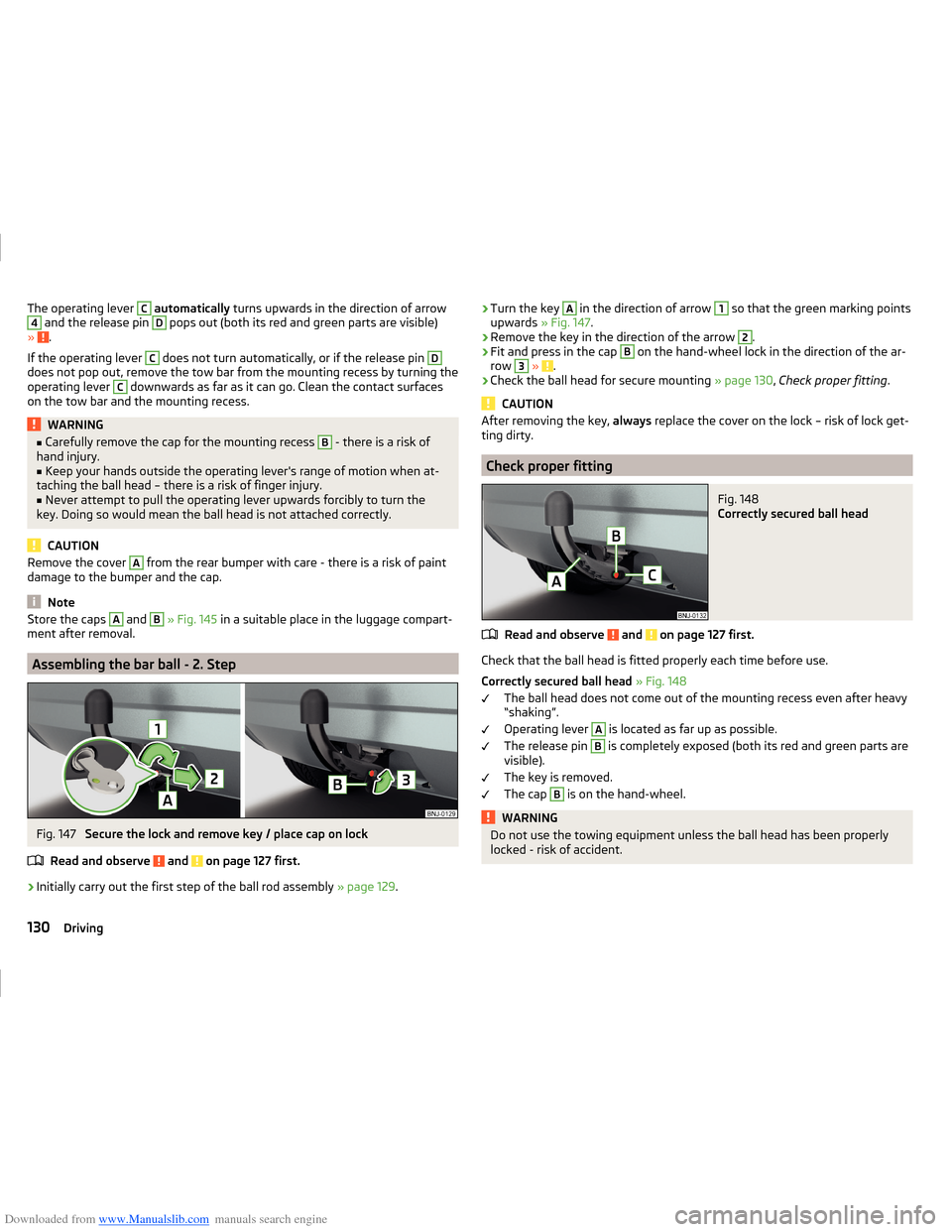
Downloaded from www.Manualslib.com manuals search engine The operating lever C automatically turns upwards in the direction of arrow4 and the release pin D pops out (both its red and green parts are visible)
» .
If the operating lever
C
does not turn automatically, or if the release pin
D
does not pop out, remove the tow bar from the mounting recess by turning the
operating lever
C
downwards as far as it can go. Clean the contact surfaces
on the tow bar and the mounting recess.
WARNING■ Carefully remove the cap for the mounting recess B - there is a risk of
hand injury.■
Keep your hands outside the operating lever's range of motion when at-
taching the ball head – there is a risk of finger injury.
■
Never attempt to pull the operating lever upwards forcibly to turn the
key. Doing so would mean the ball head is not attached correctly.
CAUTION
Remove the cover A from the rear bumper with care - there is a risk of paint
damage to the bumper and the cap.
Note
Store the caps A and B » Fig. 145 in a suitable place in the luggage compart-
ment after removal.
Assembling the bar ball - 2. Step
Fig. 147
Secure the lock and remove key / place cap on lock
Read and observe
and on page 127 first.
›
Initially carry out the first step of the ball rod assembly » page 129.
›Turn the key A in the direction of arrow 1 so that the green marking points
upwards » Fig. 147.›
Remove the key in the direction of the arrow
2
.
›
Fit and press in the cap
B
on the hand-wheel lock in the direction of the ar-
row
3
» .
›
Check the ball head for secure mounting » page 130, Check proper fitting .
CAUTION
After removing the key, always replace the cover on the lock – risk of lock get-
ting dirty.
Check proper fitting
Fig. 148
Correctly secured ball head
Read and observe and on page 127 first.
Check that the ball head is fitted properly each time before use.
Correctly secured ball head » Fig. 148
The ball head does not come out of the mounting recess even after heavy
“shaking”.
Operating lever
A
is located as far up as possible.
The release pin
B
is completely exposed (both its red and green parts are
visible).
The key is removed.
The cap
B
is on the hand-wheel.
WARNINGDo not use the towing equipment unless the ball head has been properly
locked - risk of accident.130Driving
Page 134 of 216
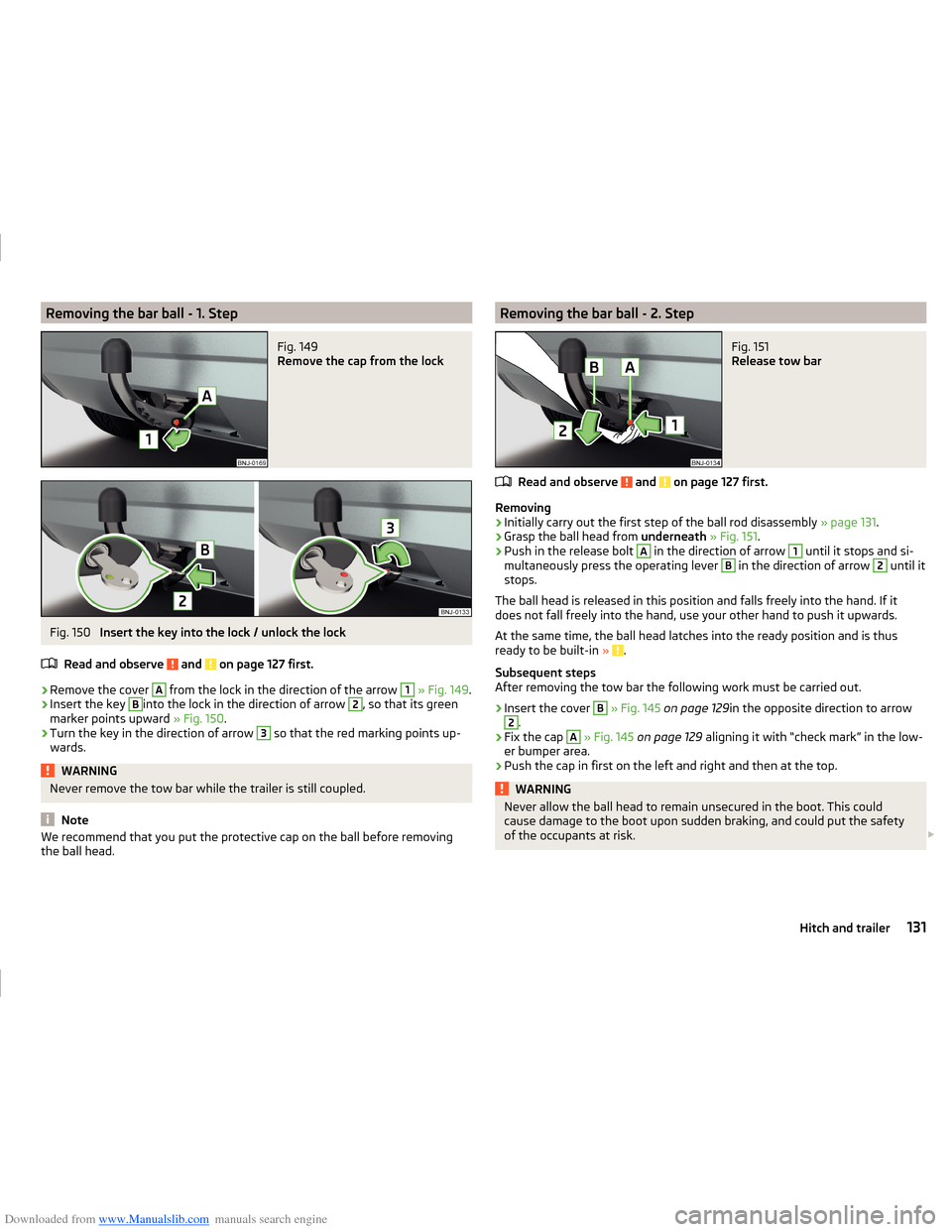
Downloaded from www.Manualslib.com manuals search engine Removing the bar ball - 1. StepFig. 149
Remove the cap from the lock
Fig. 150
Insert the key into the lock / unlock the lock
Read and observe
and on page 127 first.
›
Remove the cover
A
from the lock in the direction of the arrow
1
» Fig. 149 .
›
Insert the key
B
into the lock in the direction of arrow
2
, so that its green
marker points upward » Fig. 150.
›
Turn the key in the direction of arrow
3
so that the red marking points up-
wards.
WARNINGNever remove the tow bar while the trailer is still coupled.
Note
We recommend that you put the protective cap on the ball before removing
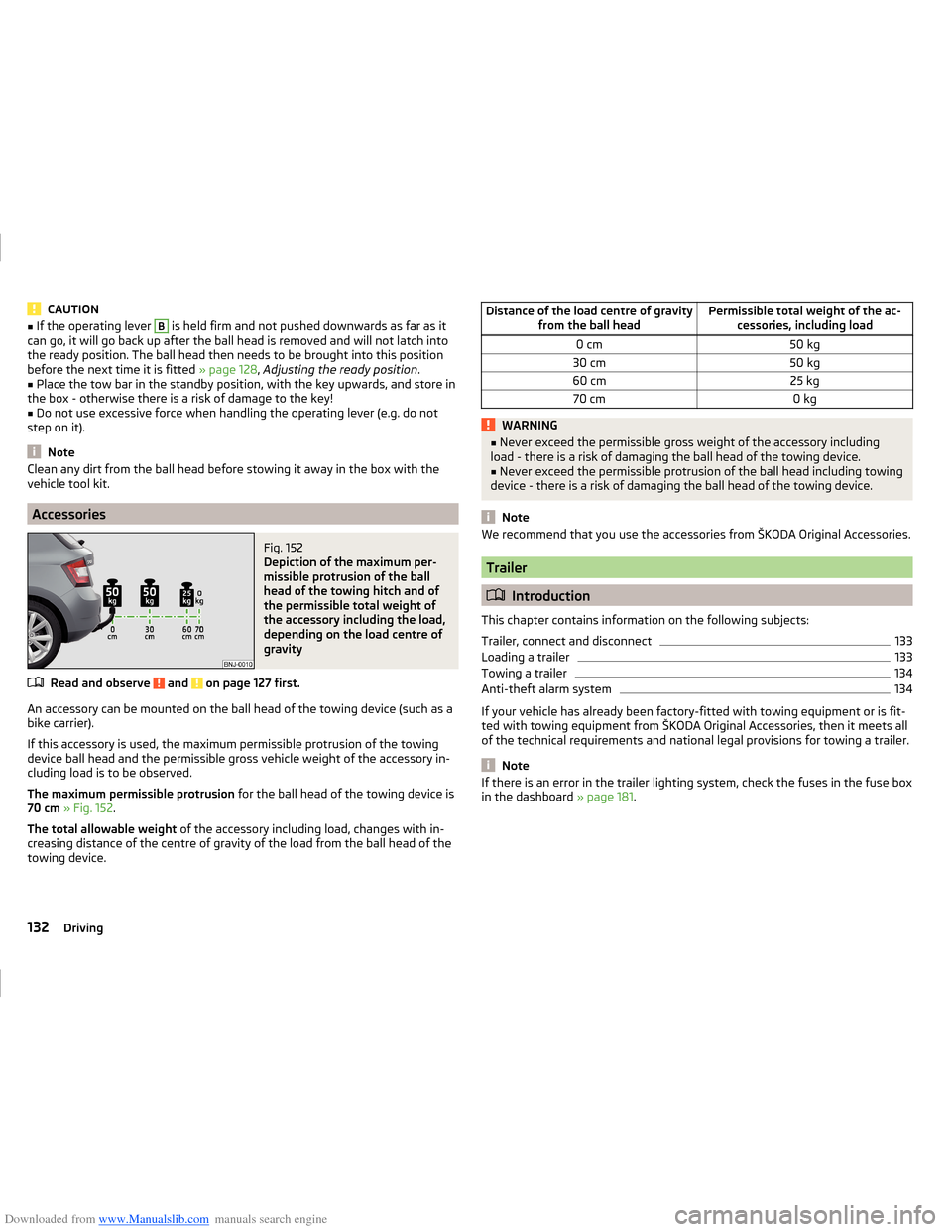
the ball head.Removing the bar ball - 2. StepFig. 151
Release tow bar
Read and observe and on page 127 first.
Removing
›
Initially carry out the first step of the ball rod disassembly » page 131.
›
Grasp the ball head from underneath » Fig. 151 .
›
Push in the release bolt
A
in the direction of arrow
1
until it stops and si-
multaneously press the operating lever
B
in the direction of arrow
2
until it
stops.
The ball head is released in this position and falls freely into the hand. If it
does not fall freely into the hand, use your other hand to push it upwards.
At the same time, the ball head latches into the ready position and is thus
ready to be built-in »
.
Subsequent steps
After removing the tow bar the following work must be carried out.
›
Insert the cover
B
» Fig. 145 on page 129 in the opposite direction to arrow
2
.
›
Fix the cap
A
» Fig. 145 on page 129 aligning it with “check mark” in the low-
er bumper area.
›
Push the cap in first on the left and right and then at the top.
WARNINGNever allow the ball head to remain unsecured in the boot. This could
cause damage to the boot upon sudden braking, and could put the safety
of the occupants at risk. 131Hitch and trailer
Page 135 of 216
Downloaded from www.Manualslib.com manuals search engine CAUTION■If the operating lever B is held firm and not pushed downwards as far as it
can go, it will go back up after the ball head is removed and will not latch into
the ready position. The ball head then needs to be brought into this position
before the next time it is fitted » page 128, Adjusting the ready position .■
Place the tow bar in the standby position, with the key upwards, and store in
the box - otherwise there is a risk of damage to the key!
■
Do not use excessive force when handling the operating lever (e.g. do not
step on it).
Note
Clean any dirt from the ball head before stowing it away in the box with the
vehicle tool kit.
Accessories
Fig. 152
Depiction of the maximum per-
missible protrusion of the ball
head of the towing hitch and of
the permissible total weight of
the accessory including the load,
depending on the load centre of
gravity
Read and observe and on page 127 first.
An accessory can be mounted on the ball head of the towing device (such as a
bike carrier).
If this accessory is used, the maximum permissible protrusion of the towing
device ball head and the permissible gross vehicle weight of the accessory in-
cluding load is to be observed.
The maximum permissible protrusion for the ball head of the towing device is
70 cm » Fig. 152 .
The total allowable weight of the accessory including load, changes with in-
creasing distance of the centre of gravity of the load from the ball head of the
towing device.
Distance of the load centre of gravity from the ball headPermissible total weight of the ac-cessories, including load0 cm50 kg30 cm50 kg60 cm25 kg70 cm0 kgWARNING■Never exceed the permissible gross weight of the accessory including
load - there is a risk of damaging the ball head of the towing device.■
Never exceed the permissible protrusion of the ball head including towing
device - there is a risk of damaging the ball head of the towing device.
Note
We recommend that you use the accessories from ŠKODA Original Accessories.
Trailer
Introduction
This chapter contains information on the following subjects:
Trailer, connect and disconnect
133
Loading a trailer
133
Towing a trailer
134
Anti-theft alarm system
134
If your vehicle has already been factory-fitted with towing equipment or is fit-
ted with towing equipment from ŠKODA Original Accessories, then it meets all
of the technical requirements and national legal provisions for towing a trailer.
Note
If there is an error in the trailer lighting system, check the fuses in the fuse box
in the dashboard » page 181.132Driving