instrument cluster SKODA FABIA 2014 3.G / NJ Operating Instruction Manual
[x] Cancel search | Manufacturer: SKODA, Model Year: 2014, Model line: FABIA, Model: SKODA FABIA 2014 3.G / NJPages: 216, PDF Size: 30.9 MB
Page 129 of 216
Downloaded from www.Manualslib.com manuals search engine The tyre pressure monitoring function monitors (hereinafter referred to only as
a system) the tyre pressure while driving.
When changing the tyre inflation pressure, the warning light illuminates
in
the instrument cluster and an audible signal is heard.
Information on the procedure for the indication of change in tyre pressure val- ues » page 34 .
The system can only function properly if the tyres have the prescribed tyre
pressure and this pressure values are stored in the system.WARNING■ The correct tyre pressure values is always the driver's responsibility. The
tyre pressure should be checked regularly » page 161.■
The system cannot warn in case of very rapid loss of tyre pressure, e.g. in
the event of a sudden puncture.
Save tyre pressure values
Read and observe
on page 126 first.
The tyre pressure valuesare always stored in the system, if one of the follow-ing events is present.
› Change of tyre pressure values.
› Change one or more wheels.
› Change in position of a wheel on the vehicle.
› The warning light
in the instrument cluster.
The storage of the tyre pressure values depends on equipment, either in the
infotainment or by pressing a button.
WARNINGBefore storing the tyre pressures they must be inflated to the specified in-
flation pressure » page 161. If incorrect pressure values are storedthe sys-
tem may not warn even with a tyre pressure that is too low.
CAUTION
The tyre pressure values should be stored every 10 000 km or once a year to
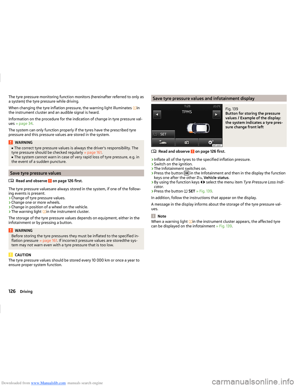
ensure proper system function.Save tyre pressure values and infotainment displayFig. 139
Button for storing the pressure
values / Example of the display:
the system indicates a tyre pres-
sure change front left
Read and observe on page 126 first.
›
Inflate all of the tyres to the specified inflation pressure.
›
Switch on the ignition.
›
The Infotainment switches on.
›
Press the button in the Infotainment and then in the display the function
keys one after the other ,
Vehicle status .
›
By using the function keys
select the menu item
Tyre Pressure Loss Indi-
cator .
›
Press the button
SET » Fig. 139 .
In addition, follow the instructions that appear on the display.
A message in the display informs about the storage of the tyre pressure val-
ues.
Note
When a warning light in the instrument cluster appears, the affected tyre
can be displayed on the infotainment » Fig. 139.126Driving
Page 130 of 216
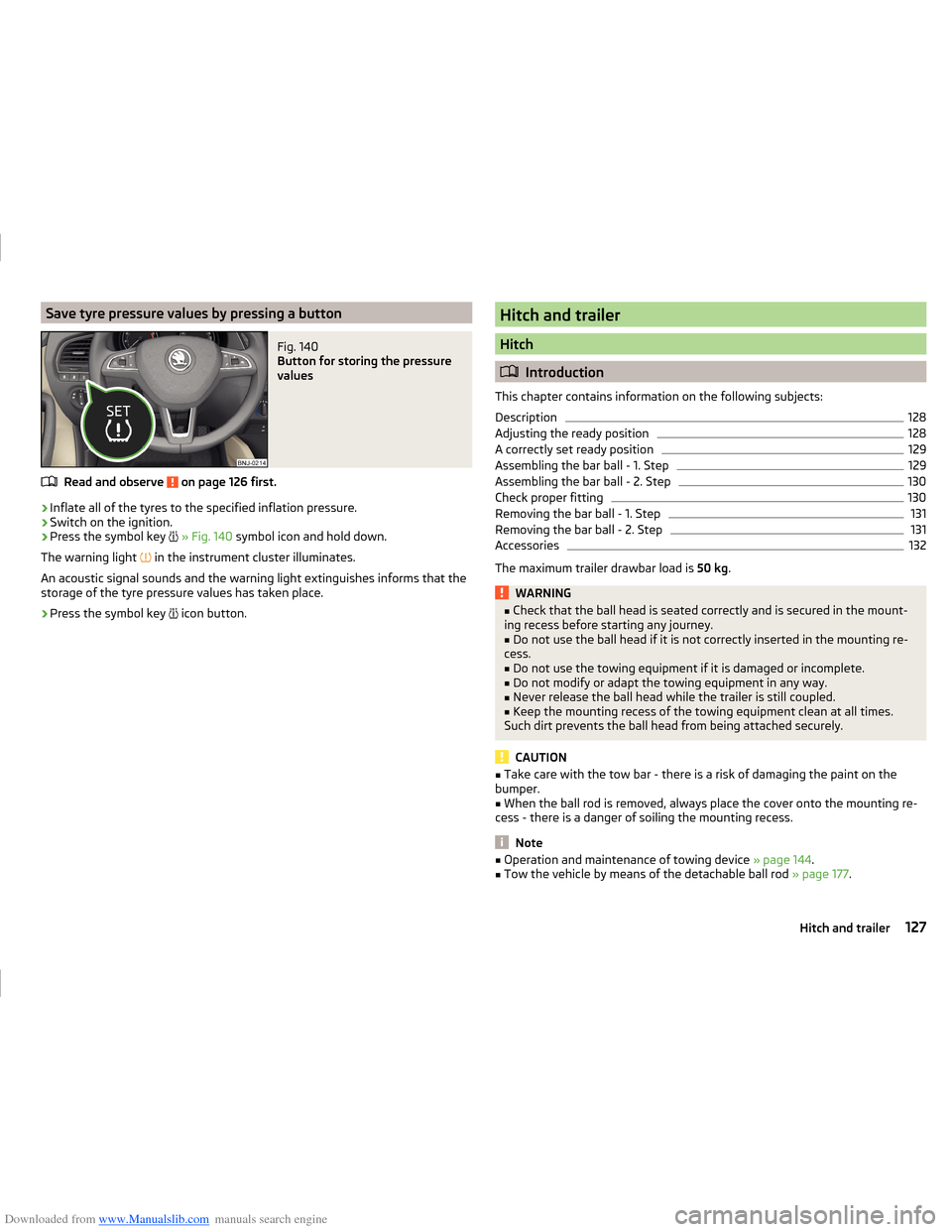
Downloaded from www.Manualslib.com manuals search engine Save tyre pressure values by pressing a buttonFig. 140
Button for storing the pressure
values
Read and observe on page 126 first.
›
Inflate all of the tyres to the specified inflation pressure.
›
Switch on the ignition.
›
Press the symbol key
» Fig. 140 symbol icon and hold down.
The warning light in the instrument cluster illuminates.
An acoustic signal sounds and the warning light extinguishes informs that the
storage of the tyre pressure values has taken place.
›
Press the symbol key icon button.
Hitch and trailer
Hitch
Introduction
This chapter contains information on the following subjects:
Description
128
Adjusting the ready position
128
A correctly set ready position
129
Assembling the bar ball - 1. Step
129
Assembling the bar ball - 2. Step
130
Check proper fitting
130
Removing the bar ball - 1. Step
131
Removing the bar ball - 2. Step
131
Accessories
132
The maximum trailer drawbar load is 50 kg.
WARNING■
Check that the ball head is seated correctly and is secured in the mount-
ing recess before starting any journey.■
Do not use the ball head if it is not correctly inserted in the mounting re-
cess.
■
Do not use the towing equipment if it is damaged or incomplete.
■
Do not modify or adapt the towing equipment in any way.
■
Never release the ball head while the trailer is still coupled.
■
Keep the mounting recess of the towing equipment clean at all times.
Such dirt prevents the ball head from being attached securely.
CAUTION
■ Take care with the tow bar - there is a risk of damaging the paint on the
bumper.■
When the ball rod is removed, always place the cover onto the mounting re-
cess - there is a danger of soiling the mounting recess.
Note
■ Operation and maintenance of towing device » page 144.■Tow the vehicle by means of the detachable ball rod » page 177.127Hitch and trailer
Page 141 of 216
Downloaded from www.Manualslib.com manuals search engine any other agreements. You should keep the confirmed warranty certificate and
the receipt for these accessories for this period, so that the commencement of
the warranty term may be verified.
In addition, ŠKODA Service Partners also stock a range of suitable car care
products as well as those parts which are subject to natural wear and tear,
such as tyres, batteries, bulbs and wiper blades.
Note
The accessories authorized by ŠKODA AUTO a.s. will be offered by the ŠKODA
Partners in all countries where ŠKODA AUTO a.s. has a sales and service net- work. This will usually be in the form of a printed catalogue of Original ŠKODA
Accessories, in the form of separate printed brochures or in the form of offers
for ŠKODA Genuine Accessories on the ŠKODA Partner's website.
Spoiler
Read and observe
on page 136 first.
If your new vehicle is fitted with a spoiler on the front bumper in combination
with the spoiler on the luggage compartment lid, then the following instruc-
tions must be adhered to.
› For safety reasons the vehicle must only ever be equipped with a spoiler on
the front bumper in combination with the associated spoiler on the tailgate.
› A spoiler cannot be fitted alone on the front bumper nor in combination with-
out a spoiler on the tailgate or in combination with an inappropriate spoiler
on the tailgate.
› We recommend that you consult a ŠKODA Service Partner for any repairs, re-
placement, fitting or removal of spoilers.
WARNING■ Work not properly performed on the spoilers on your vehicle can result in
faults - there is a risk of an accident and serious injury.■
If a front spoiler, full wheel trim, etc. is mounted retrospectively, it must
be ensured that the air supply to the front wheel brakes is not reduced.
The front brakes may overheat, which can have a negative impact on the
functioning of the braking system – there is a risk of an accident.
Component protection
Read and observe
on page 136 first.
Some electronic vehicle components (such as the instrument cluster) are fac-
tory-equipped with component protection.
Component protection has been developed as a protection mechanism for the
following situations.
› Impairment of factory- or garage-fitted electronic components after installa-
tion in another vehicle (for example, after a theft).
› Impairment of electronic components used outside the vehicle.
› The possibility of a legitimate installation or change of electronic compo-
nents for repairs at a specialist garage.
The activated component protection can be realized by functional limitations
of the specific electronic component. Seek help from a specialist garage.
Airbags
Read and observe
on page 136 first.
WARNING■Adjustments, repairs and modifications which have been carried out un-
professionally can cause damage, operational faults, and can also seriously
impair the effectiveness of airbag system – there is the risk of an accident
and fatal injury.■
A change in the suspension of the vehicle including the use of non-ap-
proved wheels and tyre combinations can alter the functioning of the air-
bag system - there is a risk of accident and fatal injury.
WARNINGInformation on the use of the airbag system■Never install any airbag parts into the vehicle that have been removed
from old cars or have been recycled.■
Never fit damaged airbag parts to a vehicle. The airbags may then not be
triggered properly or not at all in the event of an accident.
138General Maintenance
Page 157 of 216
Downloaded from www.Manualslib.com manuals search engine The oil level must be checked at regular intervals.
In case of low oil level, the display of the instrument cluster shows a check
mark
as well as the relevant notification » page 37. Check the oil level using
the dipstick as soon as possible. Add oil accordingly.
CAUTION
■ The oil level must never be above the range A » Fig. 159 - risk of damage to
the motor as well as the exhaust system.■
If for some reason, it is not possible to top up the engine oil under the cur-
rent circumstances,
do not continue driving! Switch off the engine and seek
assistance from a specialist garage.
■
If the oil level is above the range
A
,
do not continue to drive! Switch off
the engine and seek assistance from a specialist garage.
Replenishing
Read and observe
and on page 153 first.
›
Unscrew the cap of the engine oil filler opening » Fig. 157 on page 151 .
›
Replenish the oil in portions of 0.5 litres in accordance with the correct speci-
fications » page 153 .
›
Check the oil level » page 153.
›
Screw the lid of the engine oil filler closed carefully.
›
Pull the dipstick out as far as the stop.
Coolant
Introduction
This chapter contains information on the following subjects:
Checking the coolant level
155
Replenishing
155
The coolant provides cooling for the motor.
It consists of water and coolant additive with additives that protect the cooling
system against corrosion and prevents furring.
The coolant additive level in the coolant must be at least 40%.
The coolant additive may be increased to a maximum of 60%.
The correct mixing ratio of water and coolant additive is to be checked if nec- essary by a specialist garage or is to be restored if necessary.
The description of the coolant is shown in the coolant expansion reservoir » Fig. 160 on page 155 .WARNINGThe engine compartment of your car is a hazardous area. While working in
the engine compartment, be sure to observe the following warnings
» page 149 .■
The coolant is harmful to health.
■
Avoid contact with the coolant.
■
Coolant vapours are harmful to health.
■
Never open the end cover of the coolant expansion reservoir while the
engine is still warm. The cooling system is pressurized!
■
When opening the end cover of the coolant expansion reservoir, cover it
with a cloth to protect your face, hands and arms from hot steam or hot
coolant.
■
If any coolant splashes into your eyes, immediately rinse out your eyes
with clear water and contact a doctor as soon as possible.
■
Always keep the coolant in the original container safe from people who
are not completely independent, especially children - there is a danger of
poisoning!
■
Consult a doctor immediately if coolant is swallowed.
■
Never spill operating fluids over the hot engine - risk of fire.
CAUTION
■ Do not continue if for some reason it is not possible to fill with coolant un-
der the current circumstances! Switch off the engine and seek assistance from
a specialist garage.■
With an empty expansion tank top up coolant. The system could ventilate -
there is a risk of engine damage,
not continue! Switch off the engine and
seek assistance from a specialist garage.
■
The amount of coolant additive in the coolant must never be allowed to fall
below 40 %.
■
Over 60 % coolant additive in the coolant reduces the antifreeze protection
and coolant effectiveness.
■
A coolant additive that does not comply with the correct specification can
significantly reduce the corrosion protection of the cooling system.
■
Any faults resulting from corrosion may cause a loss of coolant and can con-
sequently result in major engine damage.
■
Do not fill the coolant above the mark
A
» Fig. 160 on page 155 .
■
If an error occurs, leading to the engine overheating, the help of a professio-
nal garage is to be sought - there is a risk of serious engine damage occurring.
154General Maintenance
Page 158 of 216
Downloaded from www.Manualslib.com manuals search engine ■Additional headlights and other attached components in front of the air inlet
impair the cooling efficiency of the coolant.■
Never cover the radiator - there is a risk of the engine overheating.
Checking the coolant level
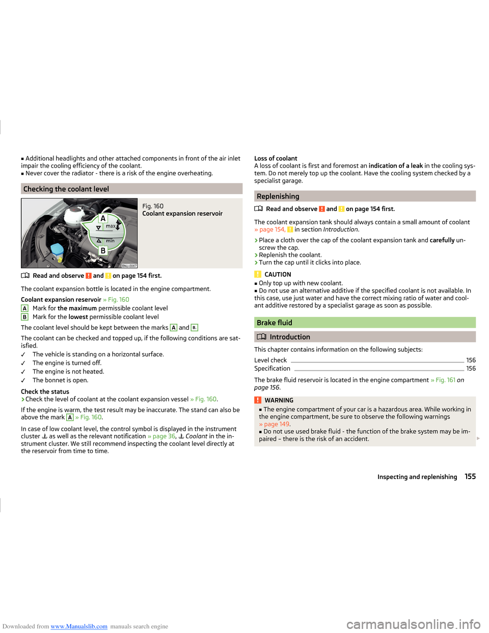
Fig. 160
Coolant expansion reservoir
Read and observe and on page 154 first.
The coolant expansion bottle is located in the engine compartment.
Coolant expansion reservoir » Fig. 160
Mark for the maximum permissible coolant level
Mark for the lowest permissible coolant level
The coolant level should be kept between the marks
A
and
B.
The coolant can be checked and topped up, if the following conditions are sat-
isfied.
The vehicle is standing on a horizontal surface.
The engine is turned off.
The engine is not heated.
The bonnet is open.
Check the status
›
Check the level of coolant at the coolant expansion vessel » Fig. 160.
If the engine is warm, the test result may be inaccurate. The stand can also be
above the mark
A
» Fig. 160 .
In case of low coolant level, the control symbol is displayed in the instrument
cluster as well as the relevant notification
» page 36,
Coolant
in the in-
strument cluster. We still recommend inspecting the coolant level directly at
the reservoir from time to time.
ABLoss of coolant
A loss of coolant is first and foremost an indication of a leak in the cooling sys-
tem. Do not merely top up the coolant. Have the cooling system checked by a
specialist garage.
Replenishing
Read and observe
and on page 154 first.
The coolant expansion tank should always contain a small amount of coolant» page 154, in section Introduction .
›
Place a cloth over the cap of the coolant expansion tank and carefully un-
screw the cap.
›
Replenish the coolant.
›
Turn the cap until it clicks into place.
CAUTION
■ Only top up with new coolant.■Do not use an alternative additive if the specified coolant is not available. In
this case, use just water and have the correct mixing ratio of water and cool-
ant additive restored by a specialist garage as soon as possible.
Brake fluid
Introduction
This chapter contains information on the following subjects:
Level check
156
Specification
156
The brake fluid reservoir is located in the engine compartment » Fig. 161 on
page 156 .
WARNING■
The engine compartment of your car is a hazardous area. While working in
the engine compartment, be sure to observe the following warnings
» page 149 .■
Do not use used brake fluid - the function of the brake system may be im-
paired – there is the risk of an accident.
155Inspecting and replenishing
Page 159 of 216
Downloaded from www.Manualslib.com manuals search engine CAUTION■Do not continue your journey if the fluid level has dropped below the “MIN”
marking » Fig. 161 on page 156 , - there is a risk of an accident! Seek help
from a specialist garage.■
Brake fluid damages the paintwork of the vehicle.
Note
■ The brake fluid is changed as part of a prescribed inspection service.■We recommend using oils from the ŠKODA Original Accessories range.
Level check
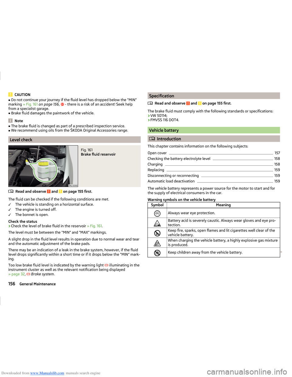
Fig. 161
Brake fluid reservoir
Read and observe and on page 155 first.
The fluid can be checked if the following conditions are met.
The vehicle is standing on a horizontal surface.
The engine is turned off.
The bonnet is open.
Check the status
›
Check the level of brake fluid in the reservoir » Fig. 161.
The level must be between the “MIN” and “MAX” markings.
A slight drop in the fluid level results in operation due to normal wear and tear
and the automatic adjustment of the brake pads.
There may be an indication of a leak in the brake system, however, if the fluid level drops significantly within a short time or if it drops below the “MIN” mark-
ing.
Too low brake fluid level is indicated by the warning light
illuminating in the
instrument cluster as well as the relevant notification being displayed
» page 32 ,
Brake system .
Specification
Read and observe
and on page 155 first.
The brake fluid must comply with the following standards or specifications:› VW 50114;
› FMVSS 116 DOT4.
Vehicle battery
Introduction
This chapter contains information on the following subjects:
Open cover
157
Checking the battery electrolyte level
158
Charging
158
Replacing
159
Disconnecting or reconnecting
159
Automatic load deactivation
159
The vehicle battery represents a power source for the motor to start and for
the supply of electrical consumers in the car.
Warning symbols on the vehicle battery
SymbolMeaningAlways wear eye protection.Battery acid is severely caustic. Always wear gloves and eye pro-
tection.Keep fire, sparks, open flames and lit cigarettes well clear of the
vehicle battery.When charging the vehicle battery, a highly explosive gas mixture
is produced.Keep children away from the vehicle battery. 156General Maintenance
Page 185 of 216
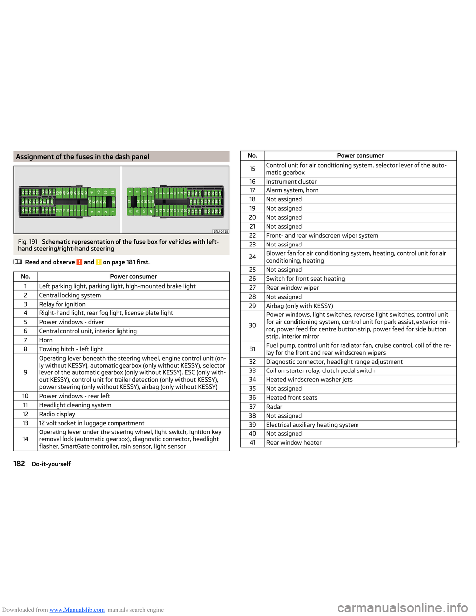
Downloaded from www.Manualslib.com manuals search engine Assignment of the fuses in the dash panelFig. 191
Schematic representation of the fuse box for vehicles with left-
hand steering/right-hand steering
Read and observe
and on page 181 first.
No.Power consumer1Left parking light, parking light, high-mounted brake light2Central locking system3Relay for ignition4Right-hand light, rear fog light, license plate light5Power windows - driver6Central control unit, interior lighting7Horn8Towing hitch - left light
9
Operating lever beneath the steering wheel, engine control unit (on-
ly without KESSY), automatic gearbox (only without KESSY), selector
lever of the automatic gearbox (only without KESSY), ESC (only with-
out KESSY), control unit for trailer detection (only without KESSY),
power steering (only without KESSY), airbag (only without KESSY)10Power windows - rear left11Headlight cleaning system12Radio display1312 volt socket in luggage compartment14Operating lever under the steering wheel, light switch, ignition key
removal lock (automatic gearbox), diagnostic connector, headlight
flasher, SmartGate controller, rain sensor, light sensorNo.Power consumer15Control unit for air conditioning system, selector lever of the auto-
matic gearbox16Instrument cluster17Alarm system, horn18Not assigned19Not assigned20Not assigned21Not assigned22Front- and rear windscreen wiper system23Not assigned24Blower fan for air conditioning system, heating, control unit for air
conditioning, heating25Not assigned26Switch for front seat heating27Rear window wiper28Not assigned29Airbag (only with KESSY)
30
Power windows, light switches, reverse light switches, control unit
for air conditioning system, control unit for park assist, exterior mir-
ror, power feed for centre button strip, power feed for side button
strip, interior mirror31Fuel pump, control unit for radiator fan, cruise control, coil of the re-
lay for the front and rear windscreen wipers32Diagnostic connector, headlight range adjustment33Coil on starter relay, clutch pedal switch34Heated windscreen washer jets35Not assigned36Heated front seats37Radar38Not assigned39Electrical auxiliary heating system40Not assigned41Rear window heater 182Do-it-yourself
Page 207 of 216
Downloaded from www.Manualslib.com manuals search engine Heating94
Control elements96
Exterior mirrors69
Seats71
HHC116
Hill Start Assist (HHC)116
Hitch127
Drawback load127
Hooks85
Horn26
I
Ice scrapers
142
Ignition lock101
Immobilizer100
Individual settings Locking
52
Unlocking52
Inertia reel13
Information system39
Compass point display45
Door warning39
Gear recommendation39
MAXI DOT display42
Multifunction display40
operation40
Service interval display46
Information system operation40
Infotainment4
Instrument cluster27
Auto-check control39
Counter for distance driven30
Display29
Fuel gauge30
Overview28
Revolution counter28
Temperature gauge29
Warning lights31
Interior care144
Natural leather145
interior light Front
64
Interior monitor55
ISOFIX22
J
Jack
167
Maintenance143
Jacking points Raise vehicle
170
Jump-starting174
K
KESSY Locking
51
Unlocking51
Key Locking
50
Start the engine101
Stopping the engine101
Switch off the ignition101
Switch on the ignition101
Unlocking50
L
Lamp failure Warning light
37
Lamps Warning light
37
Leather Natural leather care
145
LEAVING HOME63
Lever Main beam
61
Turn signal61
Levers Windscreen wipers
67
LightCockpit64
COMING HOME / LEAVING HOME63
Fog lights with CORNER function62
Lighting Luggage compartment
83
Lights59
Automatic driving lamp control61
Daylight running60
Fog lights62
Hazard warning light system63
Headlight flasher61
Headlight range adjustment60
Low beam60
Main beam61
parking lights60
Parking lights63
Rear fog light62
Replacing bulbs184
Switching on and off60
Turn signal61
Warning lights31
Locking Individual settings
52
KESSY51
Key50
Remote control50
Locking and unlocking the vehicle from the in- side
53
Locking the door without a locking cylinder Emergency
179
Low beam60
Luggage compartment83
Cover86
Fastening elements84
Fixing nets84
Flexible storage compartment88
Lighting83
Storage compartments under the floor87
unlock manually179
204Index
Page 210 of 216
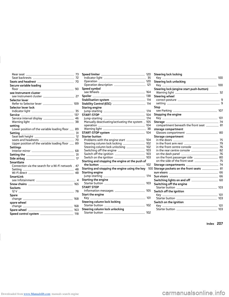
Downloaded from www.Manualslib.com manuals search engine Rear seat73
Seat backrests72
Seats and headrest70
Secure variable loading floor
90
see Instrument cluster see Instrument cluster
27
Selector lever Refer to Selector lever
109
Selector lever lock Indicator light
35
Service137
Service interval display46
Warning light38
setting Lower position of the variable loading floor
89
Setting31
Seat belt height12
seats and headrests70
Upper position of the variable loading floor89
Settings Interior mirror
68
Setting the31
Side airbag17
SmartGate Connection via the search for a Wi-Fi network
47
Setting48
Wi-Fi direct48
SmartLink see Infotainment
4
Snow chains165
Sockets 12 V
78
Spare change
168
spare wheel change
168
Spare wheel163
Speed control system118
Speed limiter120
Indicator light35
Operation120
Operation description121
Speed symbol see Wheels
164
Spoiler138
Stabilisation system114
Stability Control (ESC)114
Staring engine Jump-starting
174
START-STOP104
Jump-starting174
Manually deactivating/activating the system105
operation104
Warning light38
START-STOP system104
Starter button Problems with the engine start
104
Steering column lock locking102
Steering column lock unlocking102
Switching off the engine103
Switch off the ignition103
Switch on the ignition103
Starting and stopping the engine at the push of the button
102
Starting and stopping the engine using the key 100
Starting engine Jump-starting
174
Starting the engine Starter button
103
START STOP Information messages
105
Start the engine Key
101
Steering column lock locking Starter button
102
Steering column lock unlocking Starter button
102
Steering lock lockingKey100
Steering lock unlocking Key
100
Steering lock (engine start push-button) Warning light
32
Steering wheel correct posture
9
setting9
Stop see Parking
107
Stopping the engine Key
101
Storage74
compartment beneath the front seat81
storage compartment Glasses compartment
80
Storage compartment in the doors
75
in the front arm rest79
in the front centre console76
in the rear centre console82
on the dash panel76
on the front passenger side80
on the side of the front seat75
Storage compartments74
Storage pockets on the front seats81
sun visors66
Sun visors66
Switching lights on and off60
Switching off the engine Starter button
103
Switch off the ignition Key
101
Starter button103
Switch on the ignition Key
101
Starter button103
207Index