change time SKODA FABIA 2014 3.G / NJ Operating Instruction Manual
[x] Cancel search | Manufacturer: SKODA, Model Year: 2014, Model line: FABIA, Model: SKODA FABIA 2014 3.G / NJPages: 216, PDF Size: 30.9 MB
Page 7 of 216
Downloaded from www.Manualslib.com manuals search engine Board literature
You can always find these Operating Instructionsand the Service Plan in the
on-board instructions for your vehicle.
Depending on the equipment, the on-board literature can also include the In-
fotainment operating instructions and in some countries also the brochure On
the road .
Operating Instructions
These operating instructions apply to all body versions of the vehicle and all
related models as well as for all equipment levels .
This owner's manual describes all possible equipment versions without identi-
fying them as special equipment, model variants or market-dependent equip-
ment. Consequently, this vehicle does not contain all of the equipment com-
ponents described in this Owner's Manual.
The level of equipment of your vehicle refers to your purchase contract of the
vehicle. If you have any questions regarding the scope of equipment, please
contact a ŠKODA Partner.
The Pictures in this manual are for illustration purposes only. The illustrations
can differ in minor details from your vehicle; they are only intended to provide
general information.
ŠKODA AUTO a.s. pursues a policy of constant further development of all vehi-
cles. Each time, therefore, any changes to the vehicle occur, the scope of deliv-
ery may change in terms of its equipment and technology. The information lis-
ted in this Manual corresponds to the information available at the time of go-
ing to press.
It is therefore not possible for legal claims to be made based on the technical
details, illustrations and descriptions contained in this Owner's Manual.
Service schedule
The service plan includes the documentation of the vehicle handover informa-
tion, warranty and service events.
Infotainment operating instructions
The Infotainment manual contains a description of the Infotainment service
and possibly also some functions and vehicle systems.
Move brochure
The Move brochure contains the customer service phone number, service
number, and emergency numbers that exist in the various countries.4Board literature
Page 12 of 216
Downloaded from www.Manualslib.com manuals search engine WARNING■The front seats and all head restraints must be adjusted to match body
size at all times and the seat belt must always be fastened properly to pro-
vide the most effective levels of protection to passengers.■
Each occupant must correctly fasten the seat belt belonging to the seat.
Children must be fastened » page 20, Transporting children safely with a
suitable restraint system.
■
By sitting incorrectly, the occupant is risking life-threatening injuries.
■
The seat backrests must not be tilted too far back when driving, as this
will impair the function of the seat belts and of the airbag system – risk of
injury!
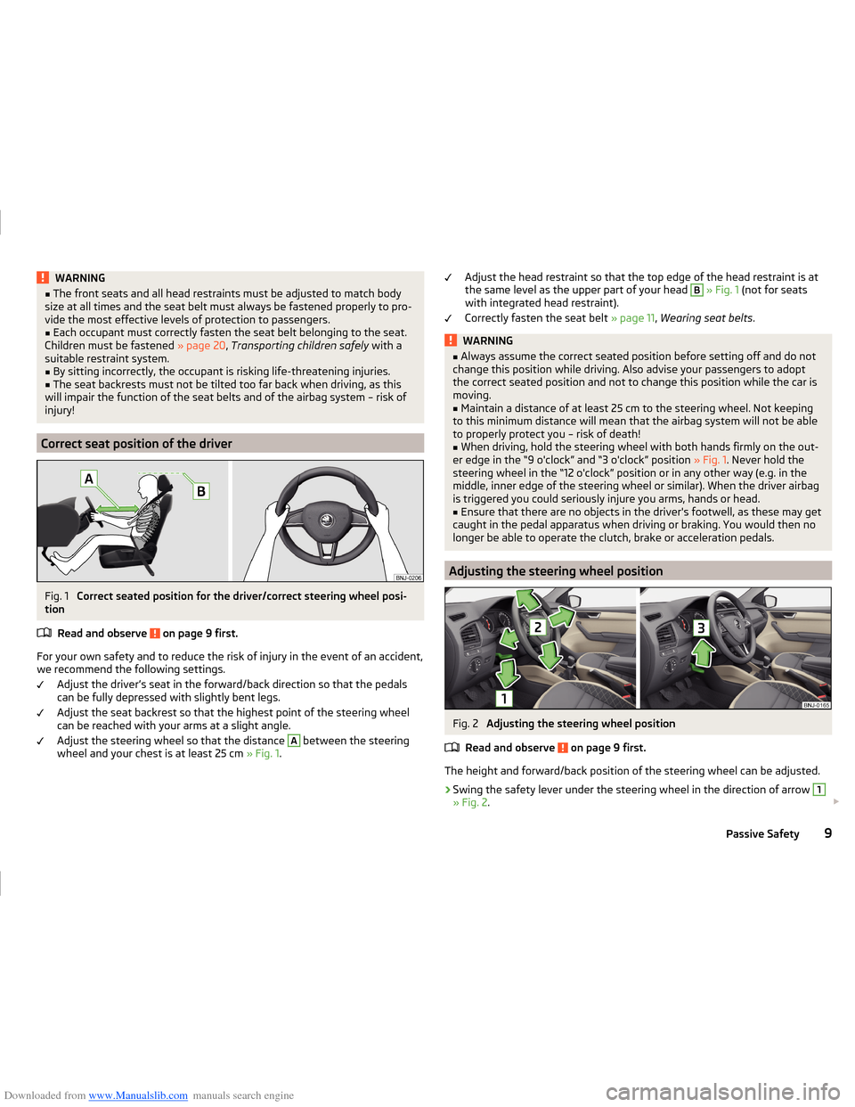
Correct seat position of the driver
Fig. 1
Correct seated position for the driver/correct steering wheel posi-
tion
Read and observe
on page 9 first.
For your own safety and to reduce the risk of injury in the event of an accident,we recommend the following settings.
Adjust the driver’s seat in the forward/back direction so that the pedalscan be fully depressed with slightly bent legs.
Adjust the seat backrest so that the highest point of the steering wheel
can be reached with your arms at a slight angle.
Adjust the steering wheel so that the distance
A
between the steering
wheel and your chest is at least 25 cm » Fig. 1.
Adjust the head restraint so that the top edge of the head restraint is at
the same level as the upper part of your head B » Fig. 1 (not for seats
with integrated head restraint).
Correctly fasten the seat belt » page 11, Wearing seat belts .WARNING■
Always assume the correct seated position before setting off and do not
change this position while driving. Also advise your passengers to adopt
the correct seated position and not to change this position while the car is
moving.■
Maintain a distance of at least 25 cm to the steering wheel. Not keeping
to this minimum distance will mean that the airbag system will not be able
to properly protect you – risk of death!
■
When driving, hold the steering wheel with both hands firmly on the out-
er edge in the “9 o'clock” and “3 o'clock” position » Fig. 1. Never hold the
steering wheel in the “12 o'clock” position or in any other way (e.g. in the middle, inner edge of the steering wheel or similar). When the driver airbag
is triggered you could seriously injure you arms, hands or head.
■
Ensure that there are no objects in the driver's footwell, as these may get
caught in the pedal apparatus when driving or braking. You would then no
longer be able to operate the clutch, brake or acceleration pedals.
Adjusting the steering wheel position
Fig. 2
Adjusting the steering wheel position
Read and observe
on page 9 first.
The height and forward/back position of the steering wheel can be adjusted.
›
Swing the safety lever under the steering wheel in the direction of arrow
1
» Fig. 2 .
9Passive Safety
Page 49 of 216
Downloaded from www.Manualslib.com manuals search engine Service interval display
Introduction
This chapter contains information on the following subjects:
Displaying the distance and days until the next service interval
46
Service messages
46
Resetting the service interval display
46
The service interval display shows the time and mileage to the next service
event.
The information regarding the service intervals can be found in the service
schedule.
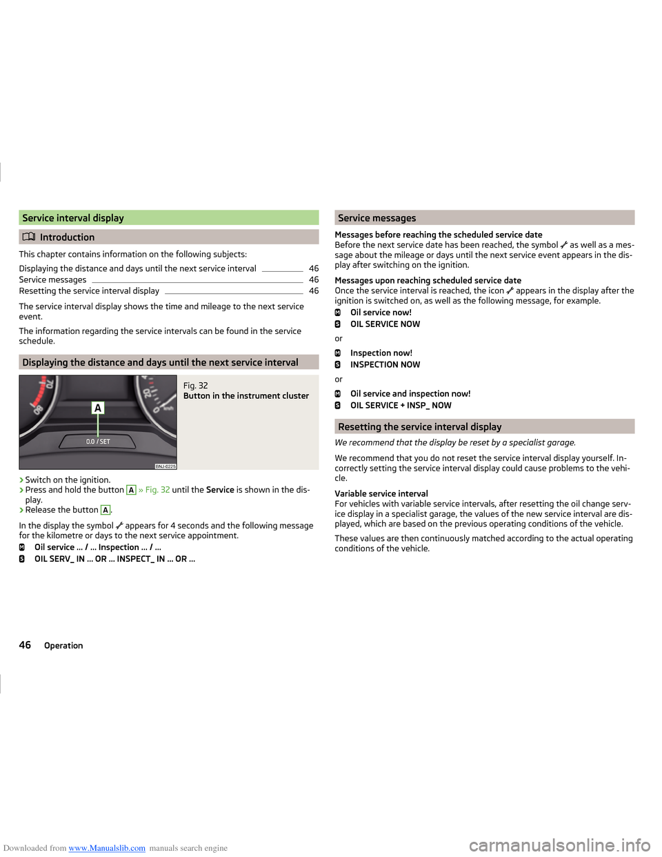
Displaying the distance and days until the next service interval
Fig. 32
Button in the instrument cluster
›
Switch on the ignition.
›
Press and hold the button
A
» Fig. 32 until the Service is shown in the dis-
play.
›
Release the button
A
.
In the display the symbol appears for 4 seconds and the following message
for the kilometre or days to the next service appointment.
Oil service … / … Inspection … / …
OIL SERV_ IN … OR … INSPECT_ IN … OR …
Service messages
Messages before reaching the scheduled service date
Before the next service date has been reached, the symbol
as well as a mes-
sage about the mileage or days until the next service event appears in the dis-
play after switching on the ignition.
Messages upon reaching scheduled service date
Once the service interval is reached, the icon
appears in the display after the
ignition is switched on, as well as the following message, for example.
Oil service now!
OIL SERVICE NOW
or Inspection now!
INSPECTION NOW
or Oil service and inspection now!
OIL SERVICE + INSP_ NOW
Resetting the service interval display
We recommend that the display be reset by a specialist garage.
We recommend that you do not reset the service interval display yourself. In-
correctly setting the service interval display could cause problems to the vehi-
cle.
Variable service interval
For vehicles with variable service intervals, after resetting the oil change serv-
ice display in a specialist garage, the values of the new service interval are dis-
played, which are based on the previous operating conditions of the vehicle.
These values are then continuously matched according to the actual operating
conditions of the vehicle.
46Operation
Page 64 of 216
Downloaded from www.Manualslib.com manuals search engine ›Hold the operating lever in this position for at least 3 seconds after switching
the ignition on.
The deactivation of the function is confirmed by an audible signal.
Activating on vehicles without Infotainment›
Switch off the ignition.
›
Pull the indicator / main beam lever towards the steering wheel, push up and
hold in this position.
›
Switch on the ignition.
›
Hold the operating lever in this position for at least 3 seconds after switching
the ignition on.
The activation of the function is confirmed by an audible signal.
WARNINGWhen the daytime running light is switched on, the parking lights (neither
at the front nor the rear) and the number plate lights are not lit. Therefore
always switch on the low beam when the visibility is poor.
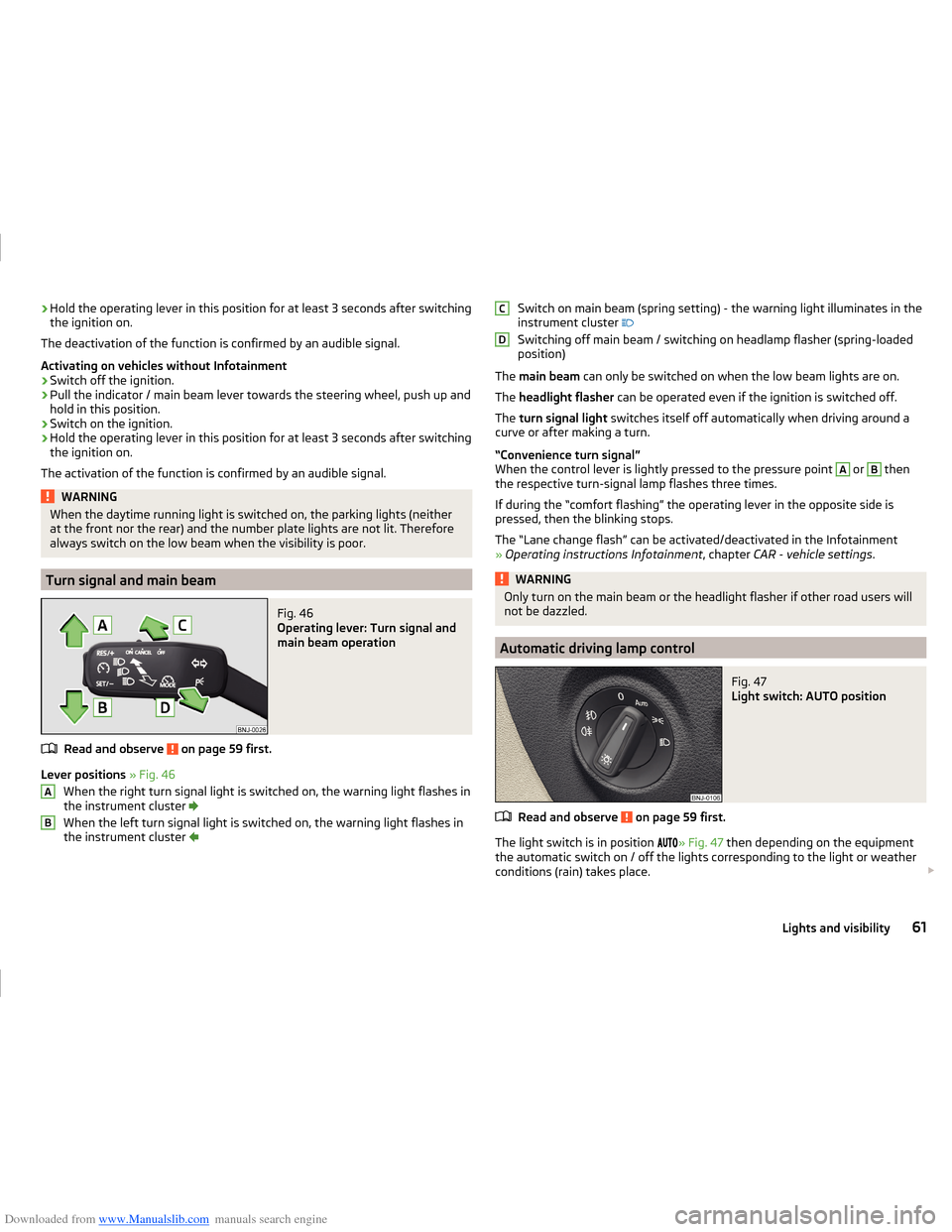
Turn signal and main beam
Fig. 46
Operating lever: Turn signal and
main beam operation
Read and observe on page 59 first.
Lever positions » Fig. 46
When the right turn signal light is switched on, the warning light flashes in
the instrument cluster
When the left turn signal light is switched on, the warning light flashes in
the instrument cluster
ABSwitch on main beam (spring setting) - the warning light illuminates in the
instrument cluster
Switching off main beam / switching on headlamp flasher (spring-loaded
position)
The main beam can only be switched on when the low beam lights are on.
The headlight flasher can be operated even if the ignition is switched off.
The turn signal light switches itself off automatically when driving around a
curve or after making a turn.
“Convenience turn signal”
When the control lever is lightly pressed to the pressure point A
or
B
then
the respective turn-signal lamp flashes three times.
If during the “comfort flashing” the operating lever in the opposite side is
pressed, then the blinking stops.
The “Lane change flash” can be activated/deactivated in the Infotainment
» Operating instructions Infotainment , chapter CAR - vehicle settings .
WARNINGOnly turn on the main beam or the headlight flasher if other road users will
not be dazzled.
Automatic driving lamp control
Fig. 47
Light switch: AUTO position
Read and observe on page 59 first.
The light switch is in position
» Fig. 47 then depending on the equipment
the automatic switch on / off the lights corresponding to the light or weather
conditions (rain) takes place.
CD61Lights and visibility
Page 113 of 216
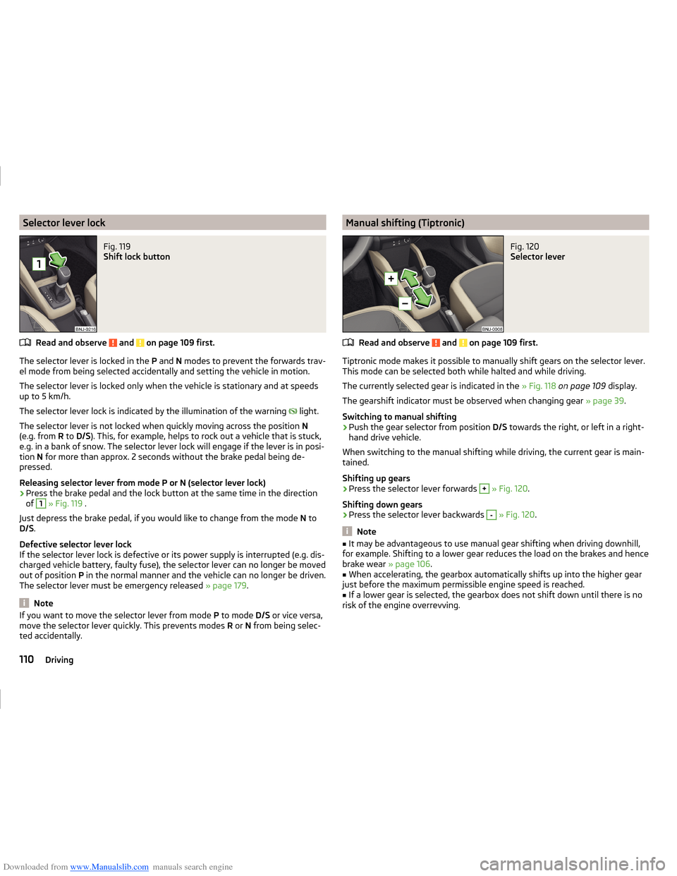
Downloaded from www.Manualslib.com manuals search engine Selector lever lockFig. 119
Shift lock button
Read and observe and on page 109 first.
The selector lever is locked in the P and N modes to prevent the forwards trav-
el mode from being selected accidentally and setting the vehicle in motion.
The selector lever is locked only when the vehicle is stationary and at speeds
up to 5 km/h.
The selector lever lock is indicated by the illumination of the warning light.
The selector lever is not locked when quickly moving across the position N
(e.g. from R to D/S ). This, for example, helps to rock out a vehicle that is stuck,
e.g. in a bank of snow. The selector lever lock will engage if the lever is in posi-
tion N for more than approx. 2 seconds without the brake pedal being de-
pressed.
Releasing selector lever from mode P or N (selector lever lock)
›
Press the brake pedal and the lock button at the same time in the direction
of
1
» Fig. 119 .
Just depress the brake pedal, if you would like to change from the mode N to
D/S .
Defective selector lever lock
If the selector lever lock is defective or its power supply is interrupted (e.g. dis-
charged vehicle battery, faulty fuse), the selector lever can no longer be moved
out of position P in the normal manner and the vehicle can no longer be driven.
The selector lever must be emergency released » page 179.
Note
If you want to move the selector lever from mode P to mode D/S or vice versa,
move the selector lever quickly. This prevents modes R or N from being selec-
ted accidentally.Manual shifting (Tiptronic)Fig. 120
Selector lever
Read and observe and on page 109 first.
Tiptronic mode makes it possible to manually shift gears on the selector lever. This mode can be selected both while halted and while driving.
The currently selected gear is indicated in the » Fig. 118 on page 109 display.
The gearshift indicator must be observed when changing gear » page 39.
Switching to manual shifting
›
Push the gear selector from position D/S towards the right, or left in a right-
hand drive vehicle.
When switching to the manual shifting while driving, the current gear is main-
tained.
Shifting up gears
›
Press the selector lever forwards
+
» Fig. 120 .
Shifting down gears
›
Press the selector lever backwards
-
» Fig. 120 .
Note
■
It may be advantageous to use manual gear shifting when driving downhill,
for example. Shifting to a lower gear reduces the load on the brakes and hence
brake wear » page 106.■
When accelerating, the gearbox automatically shifts up into the higher gear
just before the maximum permissible engine speed is reached.
■
If a lower gear is selected, the gearbox does not shift down until there is no
risk of the engine overrevving.
110Driving
Page 114 of 216
Downloaded from www.Manualslib.com manuals search engine Starting-off and drivingRead and observe
and on page 109 first.
Starting off
›
Start the engine.
›
Firmly depress and hold the brake pedal.
›
Press the lock button in the direction of
1
» Fig. 119 on page 110 and hold.
›
Move the selector lever into the desired position » page 109and then release
the lock button.
›
Release the brake pedal and accelerate.
Stopping (while the car is moving)
›
Fully depress and hold the brake pedal and bring the vehicle to a stop.
›
Keep holding the brake pedal until driving is resumed.
The selector lever position N does not have to be selected when stopping for a
short time, such as at a cross roads.
Kickdown
The kickdown function allows you to achieve maximum acceleration by your vehicle while driving.
When the accelerator pedal is fully depressed, the kickdown function is activa-
ted in any forward driving mode.
The gearbox shifts down one or more gears depending on the vehicle speed
and engine speed, and the vehicle accelerates.
The gearbox does not shift up into the highest gear until the engine has
reached its maximum revolutions for this gear range.
WARNINGRapid acceleration, particularly on slippery roads, can lead to loss of control
of the vehicle – there is a risk of an accident.
Running-in and economical driving
Introduction
This chapter contains information on the following subjects:
Running-in
111
Tips for economical driving
111
DriveGreen function
112The fuel consumption, degree of pollution and vehicle wear depend on driving
style, road condition, weather conditions and the like.
Running-in
Driving in the engine
The engine has to be run in during the first 1 500 kilometres. During this peri-
od, the driving style decides on the quality of the driving-in process.
During the first 1,000 km ,we recommend not driving faster than 3/4 of the
maximum permissible engine speed, not to drive at full throttle and not to use
a trailer.
In the range of 1,000 to 1,500 kilometres, the engine load can be increased up
to the maximum permitted engine speed.
New tyres
New tyres have to be “run in” since they do not offer optimal grip at first.
Drive especially carefully for the first 500 km or so.
New brake pads
New brake pads have to first “grind in” because these do not initially have the
best possible braking effect.
Drive especially carefully for the first 200 km or so.
Tips for economical driving
To achieve the lowest possible fuel consumption, the following instructions
must be observed.
Looking ahead when driving
Avoid unnecessary acceleration and braking.
Change gear in an energy saving and timely manner
Observe the recommended gear » page 39.
Avoid full throttle and high speeds
Fuel consumption can be reduced by half if only three-quarters of the possible
top speed of your vehicle is used.
111Starting-off and driving
Page 135 of 216
Downloaded from www.Manualslib.com manuals search engine CAUTION■If the operating lever B is held firm and not pushed downwards as far as it
can go, it will go back up after the ball head is removed and will not latch into
the ready position. The ball head then needs to be brought into this position
before the next time it is fitted » page 128, Adjusting the ready position .■
Place the tow bar in the standby position, with the key upwards, and store in
the box - otherwise there is a risk of damage to the key!
■
Do not use excessive force when handling the operating lever (e.g. do not
step on it).
Note
Clean any dirt from the ball head before stowing it away in the box with the
vehicle tool kit.
Accessories
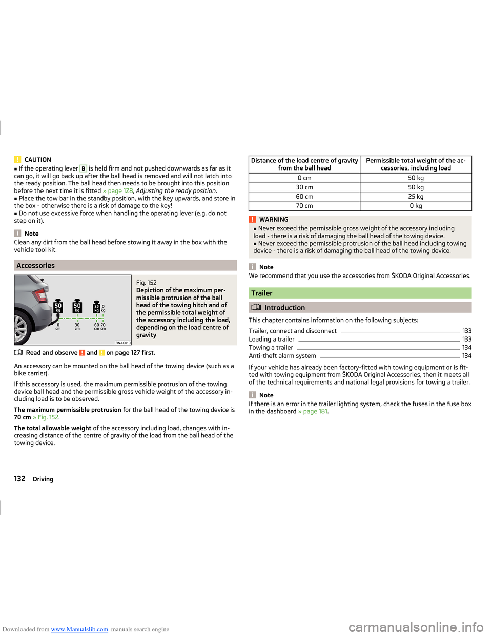
Fig. 152
Depiction of the maximum per-
missible protrusion of the ball
head of the towing hitch and of
the permissible total weight of
the accessory including the load,
depending on the load centre of
gravity
Read and observe and on page 127 first.
An accessory can be mounted on the ball head of the towing device (such as a
bike carrier).
If this accessory is used, the maximum permissible protrusion of the towing
device ball head and the permissible gross vehicle weight of the accessory in-
cluding load is to be observed.
The maximum permissible protrusion for the ball head of the towing device is
70 cm » Fig. 152 .
The total allowable weight of the accessory including load, changes with in-
creasing distance of the centre of gravity of the load from the ball head of the
towing device.
Distance of the load centre of gravity from the ball headPermissible total weight of the ac-cessories, including load0 cm50 kg30 cm50 kg60 cm25 kg70 cm0 kgWARNING■Never exceed the permissible gross weight of the accessory including
load - there is a risk of damaging the ball head of the towing device.■
Never exceed the permissible protrusion of the ball head including towing
device - there is a risk of damaging the ball head of the towing device.
Note
We recommend that you use the accessories from ŠKODA Original Accessories.
Trailer
Introduction
This chapter contains information on the following subjects:
Trailer, connect and disconnect
133
Loading a trailer
133
Towing a trailer
134
Anti-theft alarm system
134
If your vehicle has already been factory-fitted with towing equipment or is fit-
ted with towing equipment from ŠKODA Original Accessories, then it meets all
of the technical requirements and national legal provisions for towing a trailer.
Note
If there is an error in the trailer lighting system, check the fuses in the fuse box
in the dashboard » page 181.132Driving
Page 149 of 216
Downloaded from www.Manualslib.com manuals search engine Alcantara®
Dust and dirt in pores, creases and seams may chafe and damage the surface.
Therefore, they must be removed regularly at short intervals with a cloth or
vacuum cleaner.
Minor changes in colour caused by use are normal.
CAUTION
■ For Alcantara ®
seat covers, do not use any solvents, floor wax, shoe cream,
stain remover, leather cleaners or similar agents.■
Avoid leaving the vehicle in bright sunlight for long periods of time in order
to stop the artificial leather, materials or Alcantara ®
from bleaching. During ex-
tended periods of standing outdoors, protect artificial leather, fabrics or Alcan-
tara ®
by covering.
■
Some clothing materials, such as dark denim, do not have sufficient colour
fastness. This can cause damage or clearly visible discolouration to seat covers
even when treated correctly. This is particularly true for light-coloured uphols-
tery. This is not a defect in the seat cover, but poor colour fastness of the
clothing textiles.
Seat covers
Read and observe
and on page 144 first.
Electrically heated seats
Use a specific cleaning agent such as dry foam or similar to clean the covers.
»
.
Seats without seat heating
Thoroughly vacuum the seat covers with a vacuum cleaner before cleaning.
Clean the seat covers with a damp cloth or cleaning agents particularly formu-
lated for them.
Compressed areas created on the fabrics by everyday use can be removed by
brushing against the nap with a lightly moistened brush.
Always treat all parts of the upholstery so that no visible boundaries are cre-
ated. Then leave the seat to dry completely.
CAUTION
■ Do not clean the covers of electrically heated seats either with water or with
other liquids - there is a risk of damaging the seat heating system.■
Regularly vacuum dust from the seat covers using a vacuum cleaner.
■ Electrically heated seats must not be dried after cleaning by switching on the
heater.■
Do not sit on wet seats - there is a risk of stretching the upholstery.
■
Always clean the seats “from seam to seam”.
Safety belts
Read and observe
and on page 144 first.
Wash dirty seat belts with a mild, soapy solution.
Remove dirt with a soft brush.
WARNING■ The seat belts must not be removed for cleaning.■Never clean the seat belts chemically as chemical cleaning products could
destroy the fabric.■
The seat belts must not be allowed to come into contact with corrosive
liquids (such as acids etc.).
■
Inertia reel belts must be completely dried before being rolled up.
146General Maintenance
Page 155 of 216
Downloaded from www.Manualslib.com manuals search engine Radiator fanRead and observe
and on page 150 first.
The radiator fan is powered by an electric motor. Operation is controlled ac-
cording to the temperature of the coolant.
WARNINGThe fan can intermittently continue to run for approximately 10 minutes af-
ter the ignition is switched off.
Windscreen washer system
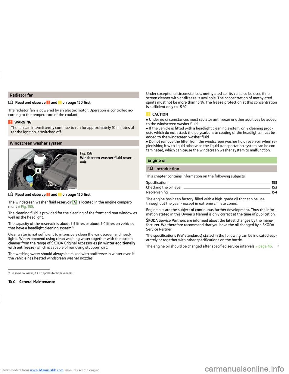
Fig. 158
Windscreen washer fluid reser-
voir
Read and observe and on page 150 first.
The windscreen washer fluid reservoir
A
is located in the engine compart-
ment » Fig. 158 .
The cleaning fluid is provided for the cleaning of the front and rear window as
well as the headlight.
The capacity of the reservoir is about 3.5 litres or about 5.4 litres on vehicles
that have a headlight cleaning system 1)
.
Clear water is not sufficient to intensively clean the windscreen and head-
lights. We recommend using clean washing water together with the screen
cleaner from the range of ŠKODA Original Accessories (in winter additionally
with antifreeze) which is capable of removing stubborn dirt.
The washing water should always be mixed with antifreeze in winter even if
the vehicle has heated windscreen washer nozzles.
Under exceptional circumstances, methylated spirits can also be used if no
screen cleaner with antifreeze is available. The concentration of methylated
spirits must not be more than 15 %. The freeze protection at this concentration
is sufficient only to -5 °C.
CAUTION
■ Under no circumstances must radiator antifreeze or other additives be added
to the windscreen washer fluid.■
If the vehicle is fitted with a headlight cleaning system, only cleaning prod-
ucts which do not attack the polycarbonate coating of the headlights must be
added to the windscreen washer fluid.
■
Do not remove the filter from the windscreen washer fluid reservoir when re-
plenishing it with liquid otherwise the liquid transportation system can be con-
taminated, which can cause the windscreen washer system to malfunction.
Engine oil
Introduction
This chapter contains information on the following subjects:
Specification
153
Checking the oil level
153
Replenishing
154
The engine has been factory-filled with a high-grade oil that can be use
throughout the year - except in extreme climate zones.
Engine oils are the subject of continuous further development. Thus the infor-
mation stated in this Owner's Manual is only correct at the time of publication.
ŠKODA Service Partners are informed about the latest changes by the manu-
facturer. We therefore recommend that you have the oil changed by a ŠKODA
Service Partner.
The specifications (VW standards) stated in the following can be indicated sep-
arately or together with other specifications on the bottle.
The engine oil should be changed after specified service intervals » page 46.
1)
In some countries, 5.4 ltr. applies for both variants.
152General Maintenance
Page 159 of 216
Downloaded from www.Manualslib.com manuals search engine CAUTION■Do not continue your journey if the fluid level has dropped below the “MIN”
marking » Fig. 161 on page 156 , - there is a risk of an accident! Seek help
from a specialist garage.■
Brake fluid damages the paintwork of the vehicle.
Note
■ The brake fluid is changed as part of a prescribed inspection service.■We recommend using oils from the ŠKODA Original Accessories range.
Level check
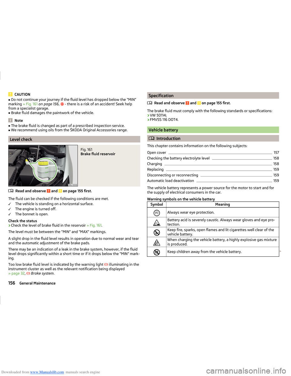
Fig. 161
Brake fluid reservoir
Read and observe and on page 155 first.
The fluid can be checked if the following conditions are met.
The vehicle is standing on a horizontal surface.
The engine is turned off.
The bonnet is open.
Check the status
›
Check the level of brake fluid in the reservoir » Fig. 161.
The level must be between the “MIN” and “MAX” markings.
A slight drop in the fluid level results in operation due to normal wear and tear
and the automatic adjustment of the brake pads.
There may be an indication of a leak in the brake system, however, if the fluid level drops significantly within a short time or if it drops below the “MIN” mark-
ing.
Too low brake fluid level is indicated by the warning light
illuminating in the
instrument cluster as well as the relevant notification being displayed
» page 32 ,
Brake system .
Specification
Read and observe
and on page 155 first.
The brake fluid must comply with the following standards or specifications:› VW 50114;
› FMVSS 116 DOT4.
Vehicle battery
Introduction
This chapter contains information on the following subjects:
Open cover
157
Checking the battery electrolyte level
158
Charging
158
Replacing
159
Disconnecting or reconnecting
159
Automatic load deactivation
159
The vehicle battery represents a power source for the motor to start and for
the supply of electrical consumers in the car.
Warning symbols on the vehicle battery
SymbolMeaningAlways wear eye protection.Battery acid is severely caustic. Always wear gloves and eye pro-
tection.Keep fire, sparks, open flames and lit cigarettes well clear of the
vehicle battery.When charging the vehicle battery, a highly explosive gas mixture
is produced.Keep children away from the vehicle battery. 156General Maintenance