clutch SKODA FABIA 2014 3.G / NJ Operating Instruction Manual
[x] Cancel search | Manufacturer: SKODA, Model Year: 2014, Model line: FABIA, Model: SKODA FABIA 2014 3.G / NJPages: 216, PDF Size: 30.9 MB
Page 10 of 216
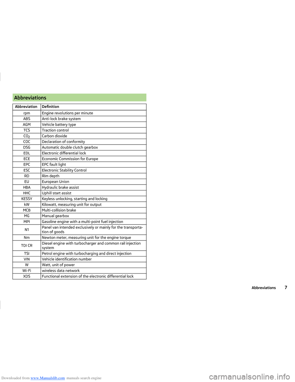
Downloaded from www.Manualslib.com manuals search engine AbbreviationsAbbreviationDefinitionrpmEngine revolutions per minuteABSAnti-lock brake systemAGMVehicle battery typeTCSTraction controlCO2Carbon dioxideCOCDeclaration of conformityDSGAutomatic double clutch gearboxEDLElectronic differential lockECEEconomic Commission for EuropeEPCEPC fault lightESCElectronic Stability ControlRDRim depthEUEuropean UnionHBAHydraulic brake assistHHCUphill start assistKESSYKeyless unlocking, starting and lockingkWKilowatt, measuring unit for outputMCBMulti-collision brakeMGManual gearboxMPIGasoline engine with a multi-point fuel injectionN1Panel van intended exclusively or mainly for the transporta-
tion of goodsNmNewton meter, measuring unit for the engine torqueTDI CRDiesel engine with turbocharger and common rail injection
systemTSIPetrol engine with turbocharging and direct injectionVINVehicle identification numberWWatt, unit of powerWi-Fiwireless data networkXDSFunctional extension of the electronic differential lock7Abbreviations
Page 12 of 216
Downloaded from www.Manualslib.com manuals search engine WARNING■The front seats and all head restraints must be adjusted to match body
size at all times and the seat belt must always be fastened properly to pro-
vide the most effective levels of protection to passengers.■
Each occupant must correctly fasten the seat belt belonging to the seat.
Children must be fastened » page 20, Transporting children safely with a
suitable restraint system.
■
By sitting incorrectly, the occupant is risking life-threatening injuries.
■
The seat backrests must not be tilted too far back when driving, as this
will impair the function of the seat belts and of the airbag system – risk of
injury!
Correct seat position of the driver
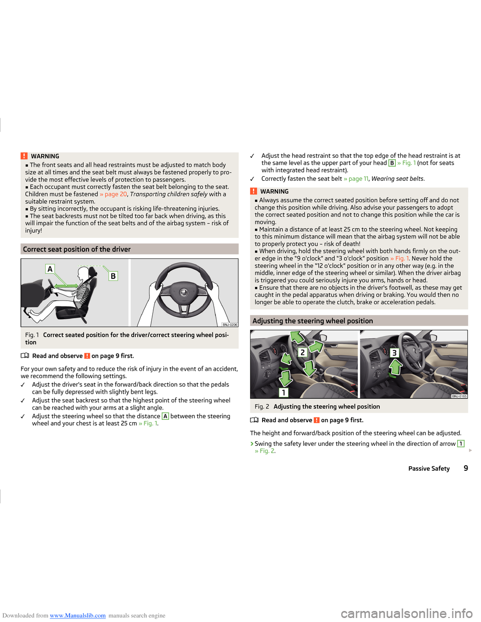
Fig. 1
Correct seated position for the driver/correct steering wheel posi-
tion
Read and observe
on page 9 first.
For your own safety and to reduce the risk of injury in the event of an accident,we recommend the following settings.
Adjust the driver’s seat in the forward/back direction so that the pedalscan be fully depressed with slightly bent legs.
Adjust the seat backrest so that the highest point of the steering wheel
can be reached with your arms at a slight angle.
Adjust the steering wheel so that the distance
A
between the steering
wheel and your chest is at least 25 cm » Fig. 1.
Adjust the head restraint so that the top edge of the head restraint is at
the same level as the upper part of your head B » Fig. 1 (not for seats
with integrated head restraint).
Correctly fasten the seat belt » page 11, Wearing seat belts .WARNING■
Always assume the correct seated position before setting off and do not
change this position while driving. Also advise your passengers to adopt
the correct seated position and not to change this position while the car is
moving.■
Maintain a distance of at least 25 cm to the steering wheel. Not keeping
to this minimum distance will mean that the airbag system will not be able
to properly protect you – risk of death!
■
When driving, hold the steering wheel with both hands firmly on the out-
er edge in the “9 o'clock” and “3 o'clock” position » Fig. 1. Never hold the
steering wheel in the “12 o'clock” position or in any other way (e.g. in the middle, inner edge of the steering wheel or similar). When the driver airbag
is triggered you could seriously injure you arms, hands or head.
■
Ensure that there are no objects in the driver's footwell, as these may get
caught in the pedal apparatus when driving or braking. You would then no
longer be able to operate the clutch, brake or acceleration pedals.
Adjusting the steering wheel position
Fig. 2
Adjusting the steering wheel position
Read and observe
on page 9 first.
The height and forward/back position of the steering wheel can be adjusted.
›
Swing the safety lever under the steering wheel in the direction of arrow
1
» Fig. 2 .
9Passive Safety
Page 77 of 216
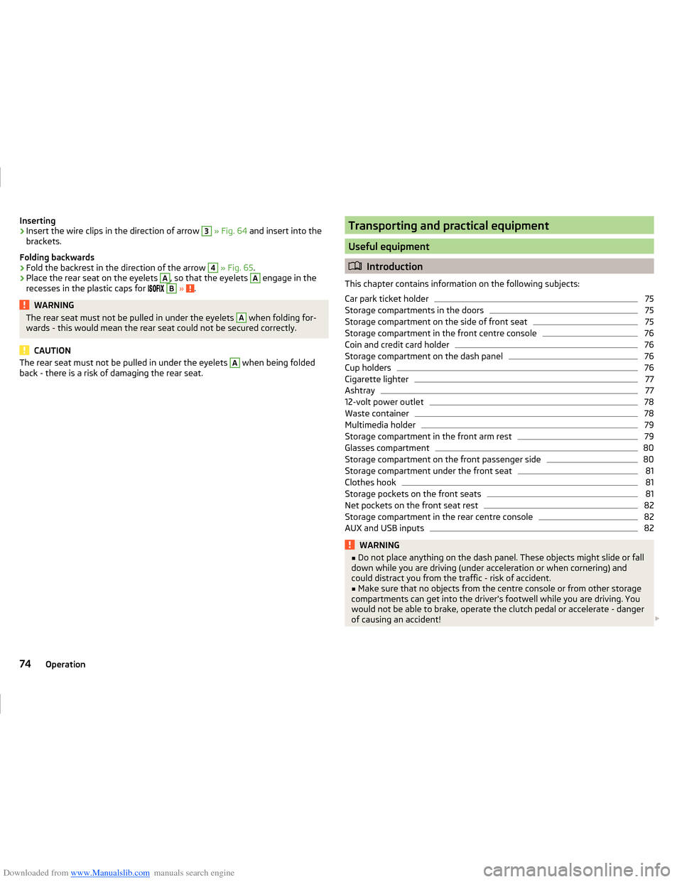
Downloaded from www.Manualslib.com manuals search engine Inserting›Insert the wire clips in the direction of arrow 3 » Fig. 64 and insert into the
brackets.
Folding backwards›
Fold the backrest in the direction of the arrow
4
» Fig. 65 .
›
Place the rear seat on the eyelets
A
, so that the eyelets
A
engage in the
recesses in the plastic caps for
B
» .
WARNINGThe rear seat must not be pulled in under the eyelets A when folding for-
wards - this would mean the rear seat could not be secured correctly.
CAUTION
The rear seat must not be pulled in under the eyelets A when being folded
back - there is a risk of damaging the rear seat.Transporting and practical equipment
Useful equipment
Introduction
This chapter contains information on the following subjects:
Car park ticket holder
75
Storage compartments in the doors
75
Storage compartment on the side of front seat
75
Storage compartment in the front centre console
76
Coin and credit card holder
76
Storage compartment on the dash panel
76
Cup holders
76
Cigarette lighter
77
Ashtray
77
12-volt power outlet
78
Waste container
78
Multimedia holder
79
Storage compartment in the front arm rest
79
Glasses compartment
80
Storage compartment on the front passenger side
80
Storage compartment under the front seat
81
Clothes hook
81
Storage pockets on the front seats
81
Net pockets on the front seat rest
82
Storage compartment in the rear centre console
82
AUX and USB inputs
82WARNING■ Do not place anything on the dash panel. These objects might slide or fall
down while you are driving (under acceleration or when cornering) and
could distract you from the traffic - risk of accident.■
Make sure that no objects from the centre console or from other storage
compartments can get into the driver's footwell while you are driving. You
would not be able to brake, operate the clutch pedal or accelerate - danger
of causing an accident!
74Operation
Page 104 of 216
Downloaded from www.Manualslib.com manuals search engine ›Switch on the ignition
» page 101.
The steering column lock is unlocked.
If the ignition switch cannot be turned on, turn the steering wheel back and forth slightly to unlock the steering lock.
Turn ignition on / off and start the engine
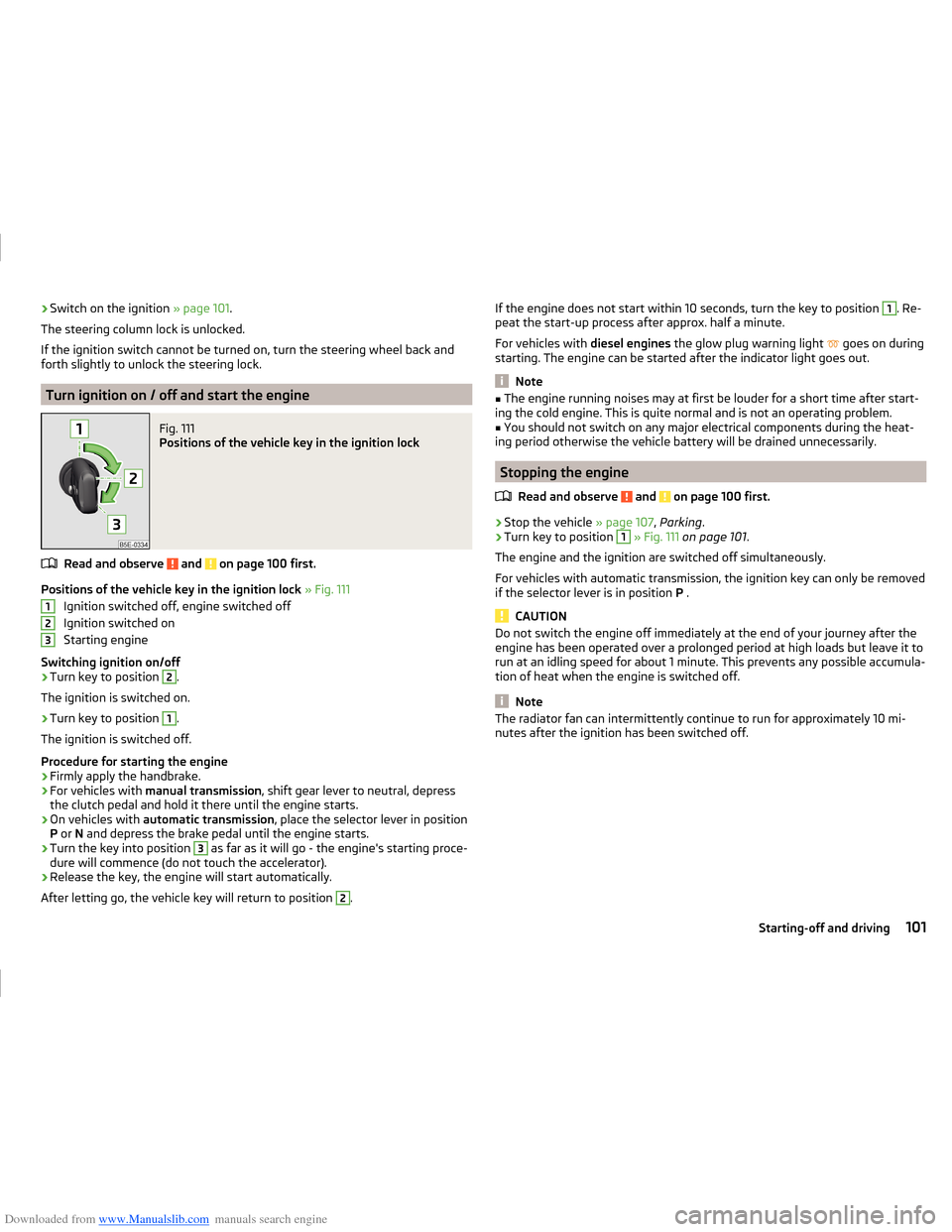
Fig. 111
Positions of the vehicle key in the ignition lock
Read and observe and on page 100 first.
Positions of the vehicle key in the ignition lock » Fig. 111
Ignition switched off, engine switched off
Ignition switched on
Starting engine
Switching ignition on/off
›
Turn key to position
2
.
The ignition is switched on.
›
Turn key to position
1
.
The ignition is switched off.
Procedure for starting the engine
›
Firmly apply the handbrake.
›
For vehicles with manual transmission , shift gear lever to neutral, depress
the clutch pedal and hold it there until the engine starts.
›
On vehicles with automatic transmission , place the selector lever in position
P or N and depress the brake pedal until the engine starts.
›
Turn the key into position
3
as far as it will go - the engine's starting proce-
dure will commence (do not touch the accelerator).
›
Release the key, the engine will start automatically.
After letting go, the vehicle key will return to position
2
.
123If the engine does not start within 10 seconds, turn the key to position 1. Re-
peat the start-up process after approx. half a minute.
For vehicles with diesel engines the glow plug warning light
goes on during
starting. The engine can be started after the indicator light goes out.
Note
■ The engine running noises may at first be louder for a short time after start-
ing the cold engine. This is quite normal and is not an operating problem.■
You should not switch on any major electrical components during the heat-
ing period otherwise the vehicle battery will be drained unnecessarily.
Stopping the engine
Read and observe
and on page 100 first.
›
Stop the vehicle » page 107, Parking .
›
Turn key to position
1
» Fig. 111 on page 101 .
The engine and the ignition are switched off simultaneously.
For vehicles with automatic transmission, the ignition key can only be removed
if the selector lever is in position P .
CAUTION
Do not switch the engine off immediately at the end of your journey after the
engine has been operated over a prolonged period at high loads but leave it to
run at an idling speed for about 1 minute. This prevents any possible accumula-
tion of heat when the engine is switched off.
Note
The radiator fan can intermittently continue to run for approximately 10 mi-
nutes after the ignition has been switched off.101Starting-off and driving
Page 106 of 216
Downloaded from www.Manualslib.com manuals search engine Switch ignition on / offRead and observe
and on page 102 first.
›
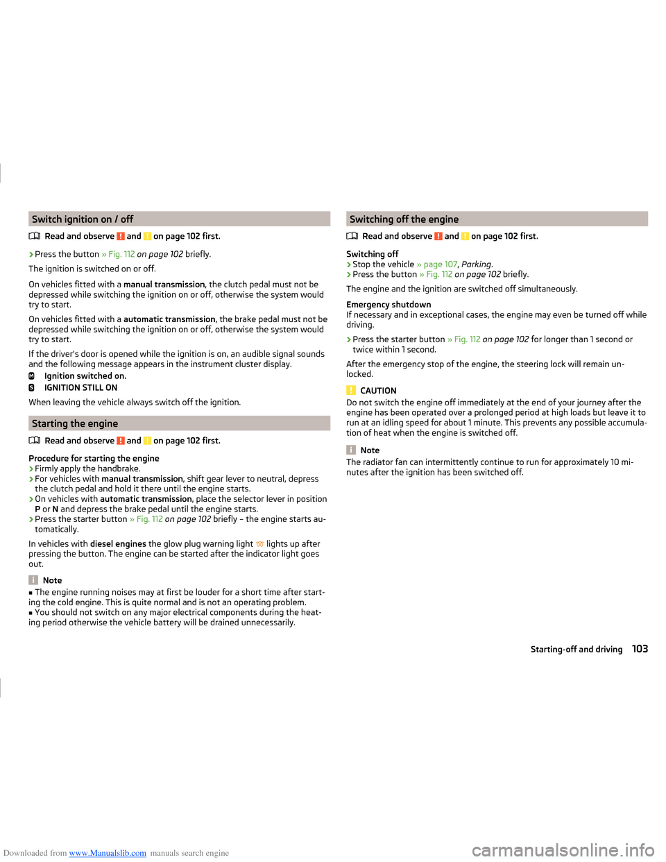
Press the button » Fig. 112 on page 102 briefly.
The ignition is switched on or off.
On vehicles fitted with a manual transmission, the clutch pedal must not be
depressed while switching the ignition on or off, otherwise the system would
try to start.
On vehicles fitted with a automatic transmission, the brake pedal must not be
depressed while switching the ignition on or off, otherwise the system would
try to start.
If the driver's door is opened while the ignition is on, an audible signal sounds
and the following message appears in the instrument cluster display.
Ignition switched on.
IGNITION STILL ON
When leaving the vehicle always switch off the ignition.
Starting the engine
Read and observe
and on page 102 first.
Procedure for starting the engine
›
Firmly apply the handbrake.
›
For vehicles with manual transmission , shift gear lever to neutral, depress
the clutch pedal and hold it there until the engine starts.
›
On vehicles with automatic transmission , place the selector lever in position
P or N and depress the brake pedal until the engine starts.
›
Press the starter button » Fig. 112 on page 102 briefly – the engine starts au-
tomatically.
In vehicles with diesel engines the glow plug warning light
lights up after
pressing the button. The engine can be started after the indicator light goes
out.
Note
■ The engine running noises may at first be louder for a short time after start-
ing the cold engine. This is quite normal and is not an operating problem.■
You should not switch on any major electrical components during the heat-
ing period otherwise the vehicle battery will be drained unnecessarily.
Switching off the engine
Read and observe
and on page 102 first.
Switching off
›
Stop the vehicle » page 107, Parking .
›
Press the button » Fig. 112 on page 102 briefly.
The engine and the ignition are switched off simultaneously.
Emergency shutdown
If necessary and in exceptional cases, the engine may even be turned off while
driving.
›
Press the starter button » Fig. 112 on page 102 for longer than 1 second or
twice within 1 second.
After the emergency stop of the engine, the steering lock will remain un-
locked.
CAUTION
Do not switch the engine off immediately at the end of your journey after the
engine has been operated over a prolonged period at high loads but leave it to
run at an idling speed for about 1 minute. This prevents any possible accumula-
tion of heat when the engine is switched off.
Note
The radiator fan can intermittently continue to run for approximately 10 mi-
nutes after the ignition has been switched off.103Starting-off and driving
Page 107 of 216
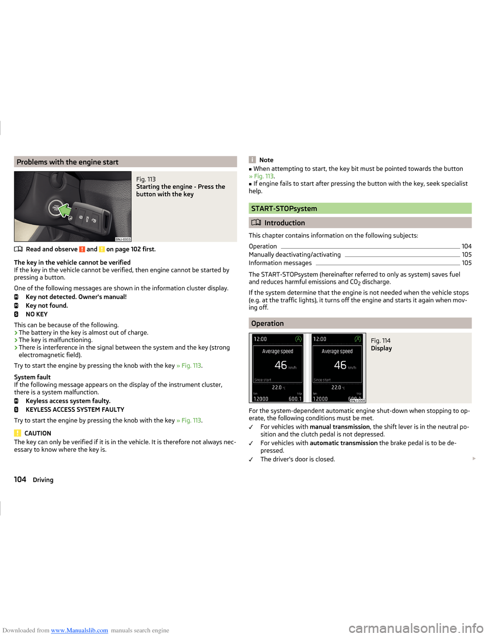
Downloaded from www.Manualslib.com manuals search engine Problems with the engine startFig. 113
Starting the engine - Press the
button with the key
Read and observe and on page 102 first.
The key in the vehicle cannot be verified
If the key in the vehicle cannot be verified, then engine cannot be started by
pressing a button.
One of the following messages are shown in the information cluster display. Key not detected. Owner's manual!
Key not found.
NO KEY
This can be because of the following.
› The battery in the key is almost out of charge.
› The key is malfunctioning.
› There is interference in the signal between the system and the key (strong
electromagnetic field).
Try to start the engine by pressing the knob with the key » Fig. 113.
System fault
If the following message appears on the display of the instrument cluster,
there is a system malfunction.
Keyless access system faulty.
KEYLESS ACCESS SYSTEM FAULTY
Try to start the engine by pressing the knob with the key » Fig. 113.
CAUTION
The key can only be verified if it is in the vehicle. It is therefore not always nec-
essary to know where the key is.Note■ When attempting to start, the key bit must be pointed towards the button
» Fig. 113 .■
If engine fails to start after pressing the button with the key, seek specialist
help.
START-STOPsystem
Introduction
This chapter contains information on the following subjects:
Operation
104
Manually deactivating/activating
105
Information messages
105
The START-STOPsystem (hereinafter referred to only as system) saves fuel
and reduces harmful emissions and CO 2 discharge.
If the system determine that the engine is not needed when the vehicle stops
(e.g. at the traffic lights), it turns off the engine and starts it again when mov-
ing off.
Operation
Fig. 114
Display
For the system-dependent automatic engine shut-down when stopping to op-
erate, the following conditions must be met.
For vehicles with manual transmission , the shift lever is in the neutral po-
sition and the clutch pedal is not depressed.
For vehicles with automatic transmission the brake pedal is to be de-
pressed.
The driver's door is closed.
104Driving
Page 109 of 216
Downloaded from www.Manualslib.com manuals search engine A system error is present. Seek help from a specialist garage.
Brakes and parking
Introduction
This chapter contains information on the following subjects:
Information for braking
106
Handbrake
107
Parking
107WARNING■ Greater physical effort is required for braking when the engine is switch-
ed off – risk of accident.■
The clutch pedal must be depressed when braking on a vehicle with man-
ual transmission, when the vehicle is in gear and at low revs. Otherwise,
the functionality of the brake system may be impaired – risk of accident!
■
When leaving the vehicle never leave persons leave unattended in the
vehicle who could release the brake. The vehicle might then move off – risk
of accident.
■
Observe the recommendations on the new brake pads » page 111.
CAUTION
Never let the brakes slip with light pressure on the pedal if braking is not nec-
essary. This causes the brakes to overheat and can also result in a longer brak-
ing distance and excessive wear.
Information for braking
Read and observe
and on page 106 first.
Wear-and-tear
The wear of the brake pads is dependent on the operating conditions and driv-
ing style.
The brake pads wear more quickly if a lot of journeys are completed in towns
and over short distances or if a very sporty style of driving is adopted.
Under these severe conditions , the thickness of the brake pads must also be
checked by a specialist garage between services.
Wet roads or road salt
The performance of the brakes can be delayed as the brake discs and brake
pads may be moist or have a coating of ice or layer of salt on them in winter.
The brakes are cleaned and dried by applying the brakes several times »
.
Corrosion
Corrosion on the brake discs and dirt on the brake pads occur if the vehicle has
been parked for a long period and if you do not make much use of the braking
system. The brakes are cleaned by applying the brakes several times »
.
Long or steep slopes
Before travelling a long distance with a steep gradient, reduce speed and shift
into the next lowest gear. As a result, the braking effect of the engine will be
used, reducing the load on the brakes. Any additional braking should be com-
pleted intermittently, not continuously.
Emergency brake display
If the brakes are applied in full and the control unit for the braking system con-
siders the situation to be dangerous for the following traffic, the brake light
flashes automatically.
After the speed was reduced below around 10 km/h or the vehicle was stop-
ped, the brake light stops flashing and the hazard warning light system
switches on. The hazard warning light system is switched off automatically af- ter accelerating or driving off again.
Fault in the brake system
If it is found that the braking distance has suddenly become longer and that
the brake pedal can be depressed further, there may be a fault in the brake
system.
Visit a specialist garage immediately and adjust your style of driving appropri-
ately as you will not know how great the damage is.
Low brake fluid level
An insufficient level of brake fluid may result in problems in the brake system.
The fluid level is monitored electronically » page 32,
Brake system
.
Brake booster
The brake booster increases the pressure generated with the brake pedal. The brake booster only operates when the engine is running.
106Driving
Page 111 of 216
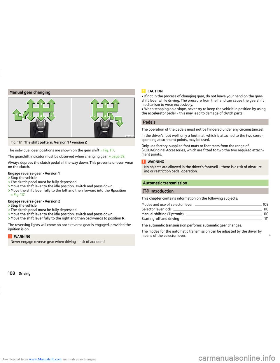
Downloaded from www.Manualslib.com manuals search engine Manual gear changingFig. 117
The shift pattern: Version 1 / version 2
The individual gear positions are shown on the gear shift » Fig. 117.
The gearshift indicator must be observed when changing gear » page 39.
Always depress the clutch pedal all the way down. This prevents uneven wear
on the clutch.
Engage reverse gear - Version 1
›
Stop the vehicle.
›
The clutch pedal must be fully depressed.
›
Move the shift lever to the idle position, switch and press down.
›
Move the shift lever fully to the left and then forward into the Rposition
» Fig. 117 .
Engage reverse gear - Version 2
›
Stop the vehicle.
›
The clutch pedal must be fully depressed.
›
Move the shift lever to the idle position, switch and press down.
›
Move the shift lever fully to the right and then backwards to position R.
The reversing lights will come on once reverse gear is engaged, provided the
ignition is on.
WARNINGNever engage reverse gear when driving – risk of accident!CAUTION■ If not in the process of changing gear, do not leave your hand on the gear-
shift lever while driving. The pressure from the hand can cause the gearshift
mechanism to wear excessively.■
When stopping on a slope, never try to keep the vehicle in position by using
the accelerator pedal – this may lead to damage of clutch parts.
Pedals
The operation of the pedals must not be hindered under any circumstances!
In the driver's foot well, only a foot mat, which is attached to the two corre-
sponding attachment points, may be used.
Only use factory-supplied foot mats or foot mats from the range of
ŠKODAOriginal Accessories, which are fitted to two the two required attach-
ment points.
WARNINGNo objects are allowed in the driver's footwell – there is a risk of obstruct-
ing or restriction pedal operation.
Automatic transmission
Introduction
This chapter contains information on the following subjects:
Modes and use of selector lever
109
Selector lever lock
110
Manual shifting (Tiptronic)
110
Starting-off and driving
111
The automatic transmission performs automatic gear changes.
The modes for the automatic transmission can be adjusted by the driver by
means of the selector lever.
108Driving
Page 122 of 216
Downloaded from www.Manualslib.com manuals search engine The Cruise Control System (CCS) maintains a set speed without you having to
actuate the accelerator pedal.
The status where the CCS maintains the speed is referred to hereinafter as the
control .WARNING■
The CCS only serves as an assistance and does not relieve the driver of
the responsibility for the vehicle operation.■
Always adjust the speed and driving style to the current visibility, weath-
er, road and traffic conditions.
■
After pressing the clutch pedal, no interrupted control occurs! For exam-
ple, if a different gear is engaged and the clutch pedal is released, control is
continued.
Functioning
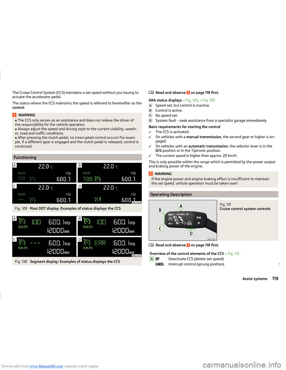
Fig. 129
Maxi DOT display: Examples of status displays the CCS
Fig. 130
Segment display: Examples of status displays the CCS
Read and observe on page 119 first.
GRA status displays » Fig. 129 , » Fig. 130
Speed set, but control is inactive.
Control is active.
No speed set.
System fault - seek assistance from a specialist garage immediately.
Basic requirements for starting the control The CCS is activated.
On vehicles with a manual transmission , the second gear or higher is en-
gaged.
On vehicles with an automatic transmission , the selector lever is in the
D/S position or in the Tiptronic position.
The current speed is higher than approx. 20 km/h.
This is only possible within the range which is permitted by the power output
and braking power of the engine.
WARNINGIf the engine power and engine braking effect is insufficient to maintain
the set speed, vehicle operation must be taken over!
Operating Description
Fig. 131
Cruise control system controls
Read and observe on page 119 first.
Overview of the control elements of the CCS » Fig. 131ADeactivate CCS (delete set speed) Interrupt control (sprung position) 119Assist systems
Page 179 of 216
Downloaded from www.Manualslib.com manuals search engine Vehicles with automatic transmission may be towed with a tow bar or a tow
rope or with the front wheels raised. If the vehicle is raised at rear, the auto-
matic gearbox is damaged!
Driver of the tow vehicle›
Engage the clutch gently when starting off or depress the accelerator partic-
ularly gently if the vehicle is fitted with an automatic gearbox.
›
Only then, approach correctly when the rope is taut.
The maximum towing speed is 50 km/h.
Driver of the towed vehicle
›
Switch on the ignition so that the steering wheel is not locked and so that
the turn signal lights, windscreen wipers and windscreen washer system can
be used.
›
Take the vehicle out of gear or move the selector lever into position N if the
vehicle is fitted with an automatic gearbox.
Please note that the brake servo unit and power steering only operate if the
engine is running. If the engine is not running, significantly more physical force
is required to depress the brake pedal and steer the vehicle.
If using a tow rope, ensure that it is always kept taught.
Both drivers should be familiar with the potential issues of towing a vehicle.
Unskilled drivers should not attempt to tow another vehicle or to be towed.
The vehicle must be transported on a special breakdown vehicle or trailer if it
is not possible to tow the vehicle in the way described or if the towing dis-
tance is greater than 50 km.
WARNING■ When towing, respect the national legal provisions, especially those
which relate to the identification of the towing vehicle and the vehicle be-
ing towed.■
Exercise increased caution when towing.
■
Spiral tow ropes must not be used for towing » Fig. 180 -
, the towing
eye may unscrew out of the vehicle - risk of accident.
■
The tow rope should not be twisted - risk of accident.
CAUTION■ Do not start engine by towing - there is a risk of damaging the engine parts.
The battery from another vehicle can be used as a jump-start aid » page 174,
Jump-starting .■
If the gearbox no longer contains any oil because of a defect, your vehicle
must only be towed with the drive wheels raised clear of the ground or on a
special breakdown vehicle or trailer.
■
To protect both vehicles when tow-starting or towing, the tow rope should
be elastic. Thus one should only use plastic fibre rope or a rope made out of a
similarly elastic material.
■
There is always a risk of excessive stresses and damage resulting at the
points to which you attach the tow rope or tow bar when you attempt to tow a
vehicle which is not standing on a paved road.
■
Attach the tow rope or the tow bar to the towing eyes » page 176 or
» page 177 to the detachable ball head of the towing equipment » page 127 .
Note
We recommend using a tow rope from ŠKODA Original Accessories available
from a ŠKODA Partner.
Front towing eye
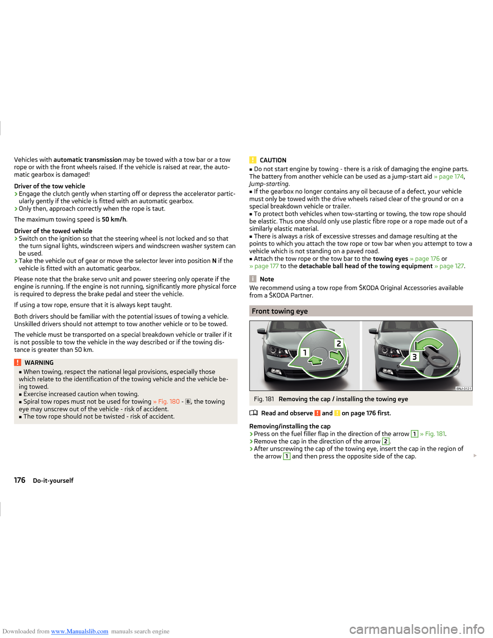
Fig. 181
Removing the cap / installing the towing eye
Read and observe
and on page 176 first.
Removing/installing the cap
›
Press on the fuel filler flap in the direction of the arrow
1
» Fig. 181 .
›
Remove the cap in the direction of the arrow
2
.
›
After unscrewing the cap of the towing eye, insert the cap in the region of
the arrow
1
and then press the opposite side of the cap.
176Do-it-yourself