warning light SKODA FABIA 2014 3.G / NJ Operating Instruction Manual
[x] Cancel search | Manufacturer: SKODA, Model Year: 2014, Model line: FABIA, Model: SKODA FABIA 2014 3.G / NJPages: 216, PDF Size: 30.9 MB
Page 5 of 216
Downloaded from www.Manualslib.com manuals search engine Table of Contents
Board literature4
Notes
5
Structure and more information about the
Operating Instructions
6
Abbreviations
Safety
Passive Safety
8
General information
8
Correct and safe seated position
8
Seat belts
11
Wearing seat belts
11
Inertia reel and belt pre-tensioners
13
Airbag system
14
Description of the airbag system
14
Airbag overview
15
Deactivating airbags
18
Transporting children safely
20
Child seat
20
Fastening systems
22
Operation
Cockpit
26
Overview
25
Instruments and warning lights
27
Instrument cluster
27
Warning lights
31
Information system
39
Driver information system
39
Driving data (Multifunction display)
40
MAXI DOT display
42Service interval display46SmartGate47
Unlocking and opening
49
Unlocking and locking
49
Anti-theft alarm system
54
Tailgate
55
Window operations
56
Lights and visibility
59
Lights
59
Interior lights
64
Visibility
65
Windscreen wipers and washers
66
Rear mirror
68
Seats and headrests
70
Seats and headrests
70
Seat features
71
Transporting and practical equipment
74
Useful equipment
74
Luggage compartment
83
Variable loading floor in the luggage
compartment
88
Bicycle carrier in the luggage compartment
90
Roof rack
93
Heating and air conditioning
94
Heating, ventilation, cooling
94
Driving
Starting-off and driving
100
Starting and stopping the engine using the
key
100
Starting and stopping the engine at the push
of the button
102
START-STOPsystem
104
Brakes and parking
106
Manual gear shifting and pedals
107Automatic transmission108Running-in and economical driving111
Avoiding damage to your vehicle
113
Assist systems
114
Braking and stabilisation systems
114
Parking assistance (ParkPilot)
116
Speed control system
118
Speed limiter
120
Front Assistant
122
Fatigue detection
125
Tyre pressure monitoring
125
Hitch and trailer
127
Hitch
127
Trailer
132
General Maintenance
Care and maintenance
136
Services, modifications and technical
alterations
136
Washing vehicle
139
Cleaning vehicle exterior
140
Interior care
144
Inspecting and replenishing
147
Fuel
147
Engine compartment
149
Engine oil
152
Coolant
154
Brake fluid
155
Vehicle battery
156
Wheels
160
Tyres and rims
160
Winter use
1642Table of Contents
Page 12 of 216
Downloaded from www.Manualslib.com manuals search engine WARNING■The front seats and all head restraints must be adjusted to match body
size at all times and the seat belt must always be fastened properly to pro-
vide the most effective levels of protection to passengers.■
Each occupant must correctly fasten the seat belt belonging to the seat.
Children must be fastened » page 20, Transporting children safely with a
suitable restraint system.
■
By sitting incorrectly, the occupant is risking life-threatening injuries.
■
The seat backrests must not be tilted too far back when driving, as this
will impair the function of the seat belts and of the airbag system – risk of
injury!
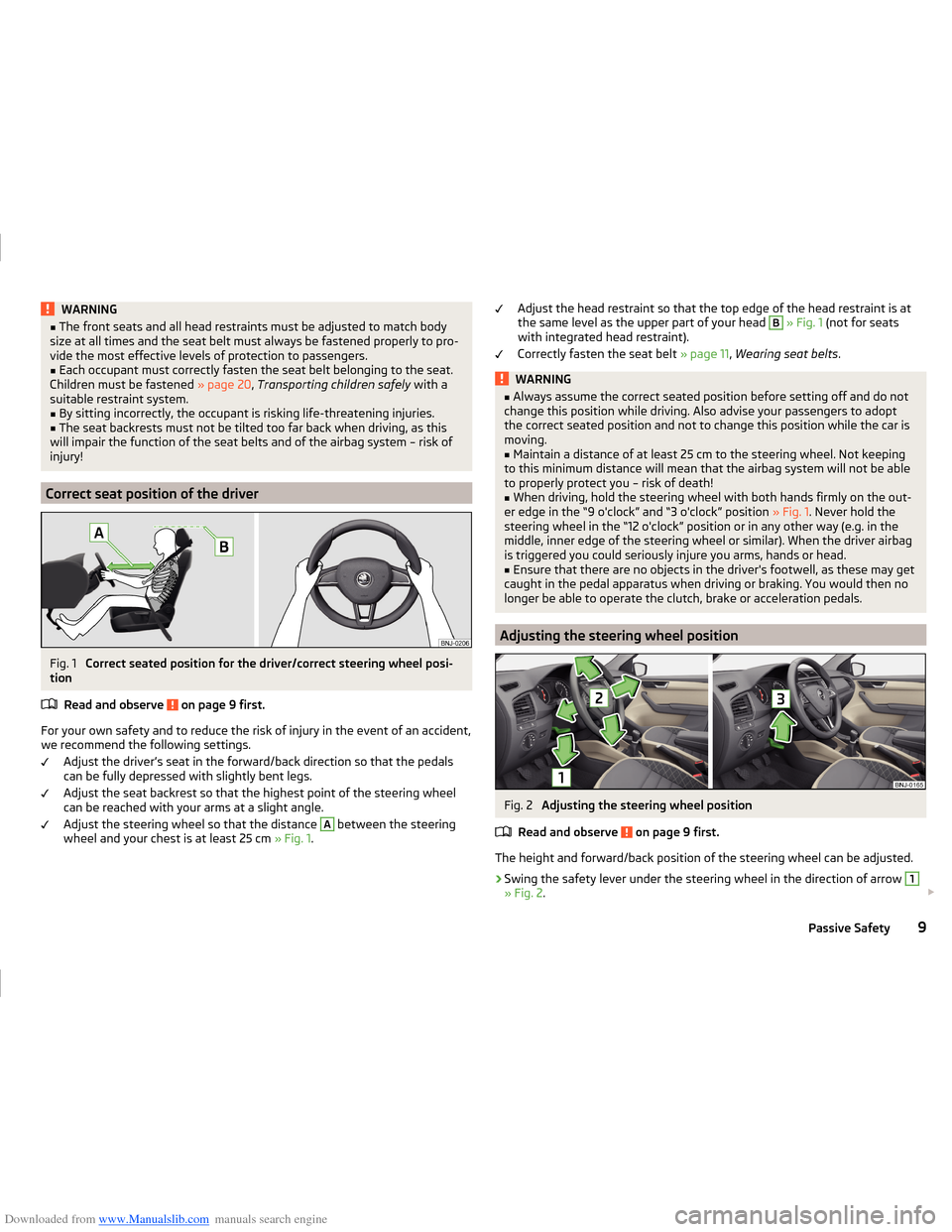
Correct seat position of the driver
Fig. 1
Correct seated position for the driver/correct steering wheel posi-
tion
Read and observe
on page 9 first.
For your own safety and to reduce the risk of injury in the event of an accident,we recommend the following settings.
Adjust the driver’s seat in the forward/back direction so that the pedalscan be fully depressed with slightly bent legs.
Adjust the seat backrest so that the highest point of the steering wheel
can be reached with your arms at a slight angle.
Adjust the steering wheel so that the distance
A
between the steering
wheel and your chest is at least 25 cm » Fig. 1.
Adjust the head restraint so that the top edge of the head restraint is at
the same level as the upper part of your head B » Fig. 1 (not for seats
with integrated head restraint).
Correctly fasten the seat belt » page 11, Wearing seat belts .WARNING■
Always assume the correct seated position before setting off and do not
change this position while driving. Also advise your passengers to adopt
the correct seated position and not to change this position while the car is
moving.■
Maintain a distance of at least 25 cm to the steering wheel. Not keeping
to this minimum distance will mean that the airbag system will not be able
to properly protect you – risk of death!
■
When driving, hold the steering wheel with both hands firmly on the out-
er edge in the “9 o'clock” and “3 o'clock” position » Fig. 1. Never hold the
steering wheel in the “12 o'clock” position or in any other way (e.g. in the middle, inner edge of the steering wheel or similar). When the driver airbag
is triggered you could seriously injure you arms, hands or head.
■
Ensure that there are no objects in the driver's footwell, as these may get
caught in the pedal apparatus when driving or braking. You would then no
longer be able to operate the clutch, brake or acceleration pedals.
Adjusting the steering wheel position
Fig. 2
Adjusting the steering wheel position
Read and observe
on page 9 first.
The height and forward/back position of the steering wheel can be adjusted.
›
Swing the safety lever under the steering wheel in the direction of arrow
1
» Fig. 2 .
9Passive Safety
Page 17 of 216
Downloaded from www.Manualslib.com manuals search engine Belt tensioners
Safety for the driver and front passenger wearing their seat belts is enhanced
by the belt tensioners fitted to the inertia reels of the front three-point seat
belts.
If there is a collision the seat belts are tightened by the belt tensioner so that
unwanted body motion is prevented.
The three-point seat belts are automatically tensioned in the event of a frontal
collision of a certain severity.
The front seat belts are automatically tensioned in the event of a side collision
of a certain severity.
Belt tensioners are not activated in the event of minor frontal, side or rear-
end collisions, in the case of a roll-over and also not in accidents in which no
major forces are produced.WARNING■ Any work on the belt tensioner system including removal and installation
of system components because of other repair work, must only be carried
out by a specialist garage.■
The protective function of the system is only adequate for a single acci-
dent. If the belt tensioners have been deployed, it is then necessary to re-
place the entire system.
Note
■ The belt tensioners can also be deployed if the seat belts are not fastened.■Smoke is generated when the belt tensioners are deployed. This is not an in-
dication of a fire in the vehicle.■
When disposing of the vehicle or parts of the belt tensioner system, comply
with national legal requirements.
Airbag system
Description of the airbag system
Introduction
This chapter contains information on the following subjects:
System description
15
Airbag deployment
15
The airbag system supplements the fastened seat belts and provides addition-
al occupant protection in severe frontal and side collisions.
The functional status of the airbag system is indicated by the indicator light
in the instrument cluster » page 34.
WARNING■
An airbag can only offer you optimal protection in combination with a
fastened seat belt .■
The airbag is not a substitute for the seat belt, but instead forms part of
the complete passive vehicle safety concept.
■
To ensure passengers are protected with the greatest possible effect
when the airbag is deployed, the front seats must be correctly adjusted to
match body size » page 8, Correct and safe seated position .
■
If you do not fasten the seat belts when driving, lean too far forward or
adopt an incorrect seated position, you are exposing yourself to increased
risk of injury in the event of an accident.
WARNINGInformation on the use of the airbag system■If there is a fault, have the airbag system checked immediately by a spe-
cialist garage. Otherwise, there is a risk of the airbag not being activated in
the event of an accident.■
No modifications of any kind must be made to parts of the airbag system.
■
Any work on the airbag system including the installation and removal of
system components due to other repair work (e.g. removal of the steering
wheel) must only be carried out by a specialist garage.
■
Never make any changes to the front bumper or the bodywork.
14Safety
Page 18 of 216
Downloaded from www.Manualslib.com manuals search engine WARNING (Continued)■Do not manipulate individual parts of the airbag system, as this might re-
sult in the airbag being deployed.■
The protective function of the airbag system is sufficient for only one ac-
cident. The airbag system must then be replaced if the airbag has been de-
ployed.
System description
Read and observe
on page 14 first.
The inflation of the airbag is carried out in a fraction of a second.
When the airbags are deployed, they fill with gas and inflate.
A grey white or red, non-harmful gas is released when the airbag is inflated.
This is perfectly normal and is not an indication of a fire in the vehicle.
Depending on the vehicle equipment, the airbag system consists of the
following parts.
› Front airbag for the driver and the front passenger
» page 16.
› Side airbags
» page 17.
› Head airbags
» page 18.
› Airbag indicator light in the instrument cluster
» page 34.
› Key switch for the front passenger airbag
» page 19.
› Warning light for the front passenger airbag in the middle of the dash panel
» page 19 .
Note
When disposing of the vehicle or parts of the airbag system, comply with na-
tional legal requirements.
Airbag deployment
Read and observe
on page 14 first.
The airbag system is only functional when the ignition is switched on.
Triggering conditions
It is not possible to generally determine which deployment conditions apply to
the airbag system in every situation. An important role is played by factors
such as the type of object that the vehicle hits (hard/soft), the impact angle, vehicle speed, etc.
A decisive factor for the deployment of the airbags is the deceleration which
occurs. If the vehicle deceleration which occurs and is measured during the
collision remains below the prescribed reference values specified in the control
unit, the airbags are not deployed although the vehicle may well suffer severe
damage to the bodywork as a consequence of the accident.
The following airbags will be deployed in the event of a severe frontal
collision.
› Driver’s front airbag.
› Front passenger airbag.
The following airbags will be deployed in the event of a severe side collision.
› Front side airbag on the side of the accident.
› Head airbags on the side of the accident.
When an airbag is deployed, the following events occur. › The interior light comes on (if the automatic operation of the interior light is
switched on - switch ).
› The ignition is switched on.
› All the doors are unlocked.
› The fuel supply to the engine is interrupted.
When there is no air bag deployment?
With minor frontal and side collisions, rear collision, overturning of the vehicle
or vehicle roll-over there is no airbag deployment.
Airbag overview
Introduction
This chapter contains information on the following subjects:
Front airbags
16
Side airbags
17
Head airbags
1815Airbag system
Page 21 of 216
Downloaded from www.Manualslib.com manuals search engine Head airbagsFig. 10
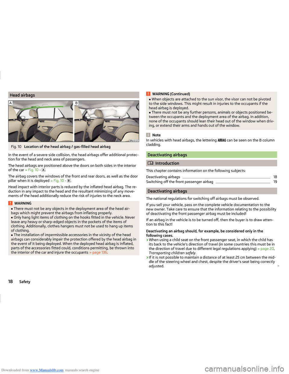
Location of the head airbag / gas-filled head airbag
In the event of a severe side collision, the head airbags offer additional protec-
tion for the head and neck area of passengers.
The head airbags are positioned above the doors on both sides in the interior
of the car » Fig. 10 -
.
The airbag covers the windows of the front and rear doors, as well as the door
pillar when it is deployed » Fig. 10 -
.
Head impact with interior parts is reduced by the inflated head airbag. The re-
duction in any impact to the head and the resultant minimizing of any move-
ments of the head additionally reduce the risk of injuries to the neck area.
WARNING■ There must not be any objects in the deployment area of the head air-
bags which might prevent the airbags from inflating properly.■
Only hang light items of clothing on the hooks fitted in the vehicle. Never
leave any heavy or sharp-edged objects in the pockets of the items of
clothing. Additionally, clothes hangers must not be used to hang up items
of clothing.
■
The installation of impermissible accessories in the vicinity of the head
airbags can considerably impair the protection offered by the head airbag in
the event of it being deployed. When the deployed head airbag is inflated,
parts of the accessories fitted could, conditions permitting, be thrown into
the interior of the car and injure the occupants » page 136.
WARNING (Continued)■
When objects are attached to the sun visor, the visor can not be pivoted
to the side windows. This might result in injuries to the occupants if the
head airbag is deployed.■
There must not be any further persons, animals or objects positioned be-
tween the occupants and the deployment area of the airbag. In addition,
none of the occupants should lean their head out of the window when driv-
ing, or extend their arms and hands out of the window.
Note
In vehicles with head airbags, the lettering can be seen on the B column
cladding.
Deactivating airbags
Introduction
This chapter contains information on the following subjects:
Deactivating airbags
18
Switching off the front passenger airbag
19
Deactivating airbags
The national regulations for switching off airbags must be observed.
If you sell your vehicle, pass on the complete vehicle documentation to the
new owner. Take care to ensure that the information relating to the possibility
of deactivating the front passenger airbag must be included!
If an airbag in the vehicle is to be turned off, then the buyer is to draw atten-
tion to this fact!
Deactivating an airbag should, for example, be considered only in the
following cases.
› When using a child seat on the front passenger seat, in which the child has
its back to the vehicle's direction of travel (in some countries this must be in
the direction of travel due to different legal regulations applying) » page 20,
Transporting children safely .
› If it is not possible to maintain a distance of at least 25 cm between the mid-
dle of the steering wheel and chest, despite the driver's seat being correctly
adjusted.
18Safety
Page 22 of 216
Downloaded from www.Manualslib.com manuals search engine ›If special attachments are required in the area of the steering wheel because
of a physical disability.
› If other seats have been installed (e.g. orthopaedic seats without side air-
bags).
The front passenger airbag can be switched off with the key-operated switch
» Fig. 11 on page 19 -
.
We recommend that you ask a ŠKODA Service Partner to switch off any other
airbags.
Deactivation indicator
Display of the airbag deactivation » page 34,
Airbag system .
Note
A ŠKODA Service Partner will be able to inform you which airbags in your vehi-
cle can/must be deactivated.
Switching off the front passenger airbag
Fig. 11
Key-operated switch for the front passenger airbag / warning light
for front seat passenger airbag deactivation
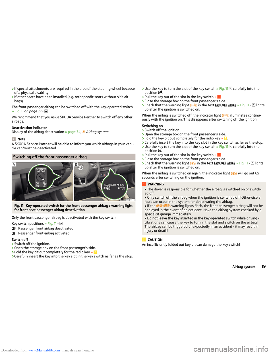
Only the front passenger airbag is deactivated with the key switch.
Key switch positions » Fig. 11 -
Passenger front airbag deactivated
Passenger front airbag activated
Switch off
›
Switch off the ignition.
›
Open the storage box on the front passenger's side.
›
Fold the key bit out completely for the radio key » .
›
Carefully insert the key into the key slot in the key switch as far as the stop.
›Use the key to turn the slot of the key switch
» Fig. 11 carefully into the
position .›
Pull the key out of the slot in the key switch » .
›
Close the storage box on the front passenger's side.
›
Check that the warning light
in the text
» Fig. 11 -
lights
up after the ignition is switched on.
When the airbag is switched off, the indicator light
illuminates continu-
ously with the ignition on. This disappears after switching off the ignition.
Switching on
›
Switch off the ignition.
›
Open the storage box on the front passenger's side.
›
Fold the key bit out completely for the radio key » .
›
Carefully insert the key into the key slot in the key switch as far as the stop.
›
Use the key to turn the slot of the key switch » Fig. 11
carefully into the
position .
›
Pull the key out of the slot in the key switch
» .
›
Close the storage box on the front passenger's side.
›
Check that the warning light
in the text
» Fig. 11 -
lights
up after the ignition is switched on.
When the airbag is switched on again, the indicator light will go out 65
seconds after switching on the ignition.
WARNING■ The driver is responsible for whether the airbag is switched on or switch-
ed off.■
Only switch off the airbag when the ignition is switched off! Otherwise a
fault can occur in the system for deactivating the airbag.
■
If the
warning lights flash, the front passenger airbag will not be
deployed in the event of an accident! Have the airbag system checked by a
specialist garage immediately.
■
Do not leave the key inserted in the key-operated switch while driving -
vibrations can cause the key to turn in the slot and switch on the airbag!
The airbag can be triggered unexpectedly in an accident - it may result in
injury or death!
CAUTION
An insufficiently folded out key bit can damage the key switch!19Airbag system
Page 29 of 216
Downloaded from www.Manualslib.com manuals search engine Operation
Cockpit
OverviewElectric windows
57
Door opening lever
50
Electric exterior mirror adjustment
69
Air outlet vent
95
Parking ticket holder
75
Operating lever:
› Turn signal light, headlight and parking light, headlight
flasher
61
› Speed regulating system
118
›Speed limiter
120
Steering wheel:
› With horn
› With driver’s front airbag
16
›With buttons for the operation of the information system
39
›With buttons for the Infotainment Control
» Infotainment
Manual , chapter Device Operation
Instrument cluster
27
Operating lever: › Windscreen wiper and wash system
66
›Information system
39
Depending on equipment fitted:
› Storage compartment
76
›Infotainment
» User manual for Infotainment
Air outlets in the central part of the dash panel
95
Bar with keys depending on the equipment fitted: ›
Left seat heating
71
›
Rear window heater
65
›
Central locking system
53
›
Hazard warning light system button
63
›
Warning light for the front seat passenger
airbag
19
›
Right seat heating
71
Interior rear-view mirror
6812345678910111213Memory card slot (in the front passenger storage compartment)
» User manual Infotainment
Front passenger airbag16
Storage compartment on the front passenger side
80
Key switch for switching off the front passenger airbag (in front
passenger storage compartment)
19
Air outlet vent
95
Power window in the front passenger door
58
Door opening lever
50
Bar with keys depending on the equipment fitted:
›
START STOP
104
›
Stability Control (ESC deactivation / activation of the ASR)
114
›
Parking aid
116
›
Tyre Press. Loss Indicator
125
Light switch
60
Bonnet release lever
151
Regulator for headlamp beam adjustment for the headlights
60
Lever for adjusting the steering wheel
9
Ignition lock
101
Fuse box
181
Pedals
108
Cup holder:
76
› with ashtray
77
›with multimedia support
79
Coin and credit card holder
76
Handbrake lever
107
Depending on equipment fitted:
› Gear shift lever (manual gearbox)
108
›Selector lever (automatic gearbox)
109
Storage compartment
76
USB / AUX input
» Infotainment Manual , chapter USB/AUX In-
puts
14151617181920212223242526272829303132333426Operation
Page 30 of 216
Downloaded from www.Manualslib.com manuals search engine Depending on equipment fitted:› 12 volt power socket78
›
Cigarette lighter
77
Depending on equipment fitted:
› Operating controls for the heating
96
›Operating controls for the air conditioning system
97
›Operating controls for Climatronic
97
Note
The layout of the controls on right-hand drive vehicles differs partially from
that shown in » Fig. 18. The symbols on the controls and switches are the
same as for left-hand drive models.3536Instruments and warning lights
Instrument cluster
Introduction
This chapter contains information on the following subjects:
Overview
28
Revolution counter
28
Display
29
Coolant temperature gauge
29
Fuel gauge
30
Counter for distance driven
30
31
The instrument cluster gives the driver basic information such as the current
speed, engine speed, the state of some vehicle systems and the like.
If there is a fault in the instrument cluster, the following message will appear
in the display.
Error: instrument cluster. Workshop!
COMBINED INSTRUM_WORKSHOP
Seek help from a specialist garage.
WARNINGConcentrate fully at all times on your driving! As the driver, you are fully re-
sponsible for road safety.
Note
If the message SAFE CP appears in the instrument cluster display, the compo-
nent protection for the instrument cluster is active. Further information
» page 138 , Component protection .27Instruments and warning lights
Page 31 of 216
Downloaded from www.Manualslib.com manuals search engine OverviewFig. 19
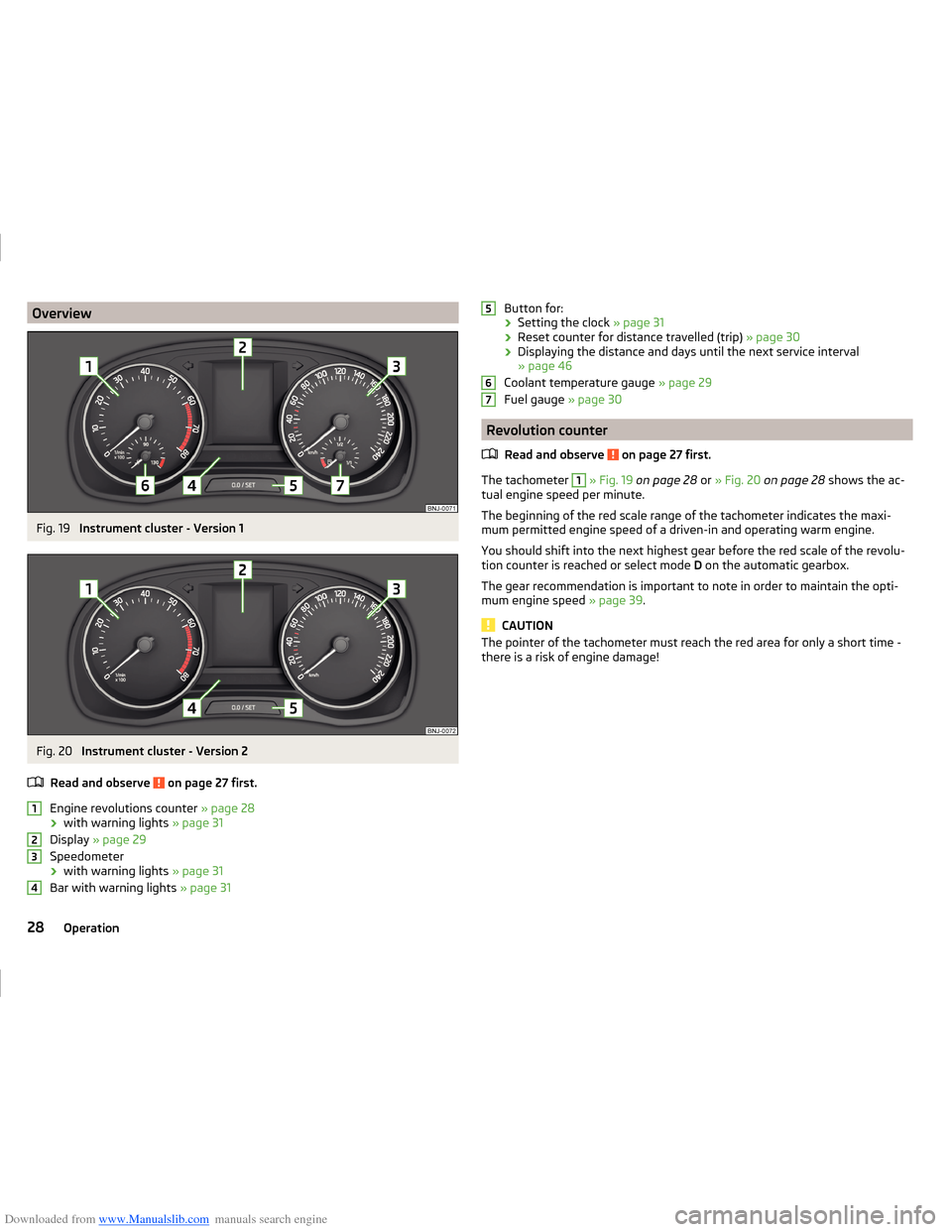
Instrument cluster - Version 1
Fig. 20
Instrument cluster - Version 2
Read and observe
on page 27 first.
Engine revolutions counter » page 28
› with warning lights
» page 31
Display » page 29
Speedometer › with warning lights
» page 31
Bar with warning lights » page 31
1234Button for:
› Setting the clock
» page 31
› Reset counter for distance travelled (trip)
» page 30
› Displaying the distance and days until the next service interval
» page 46
Coolant temperature gauge » page 29
Fuel gauge » page 30
Revolution counter
Read and observe
on page 27 first.
The tachometer
1
» Fig. 19 on page 28 or » Fig. 20 on page 28 shows the ac-
tual engine speed per minute.
The beginning of the red scale range of the tachometer indicates the maxi-
mum permitted engine speed of a driven-in and operating warm engine.
You should shift into the next highest gear before the red scale of the revolu- tion counter is reached or select mode D on the automatic gearbox.
The gear recommendation is important to note in order to maintain the opti-
mum engine speed » page 39.
CAUTION
The pointer of the tachometer must reach the red area for only a short time -
there is a risk of engine damage!56728Operation
Page 32 of 216
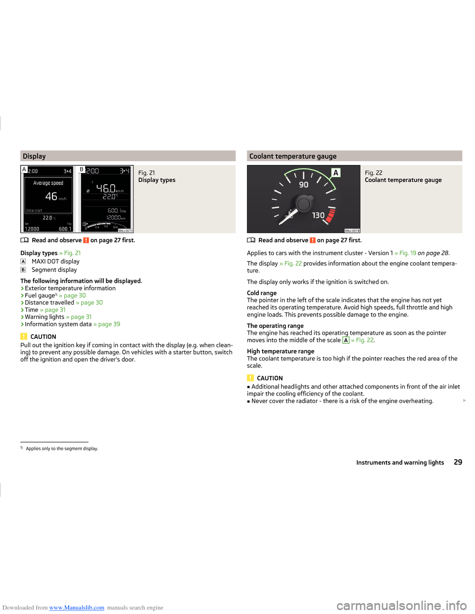
Downloaded from www.Manualslib.com manuals search engine DisplayFig. 21
Display types
Read and observe on page 27 first.
Display types » Fig. 21
MAXI DOT display
Segment display
The following information will be displayed.
› Exterior temperature information
› Fuel gauge 1)
» page 30
› Distance travelled
» page 30
› Time
» page 31
› Warning lights
» page 31
› Information system data
» page 39
CAUTION
Pull out the ignition key if coming in contact with the display (e.g. when clean-
ing) to prevent any possible damage. On vehicles with a starter button, switch
off the ignition and open the driver's door.Coolant temperature gaugeFig. 22
Coolant temperature gauge
Read and observe on page 27 first.
Applies to cars with the instrument cluster - Version 1 » Fig. 19 on page 28 .
The display » Fig. 22 provides information about the engine coolant tempera-
ture.
The display only works if the ignition is switched on.
Cold range
The pointer in the left of the scale indicates that the engine has not yet
reached its operating temperature. Avoid high speeds, full throttle and high
engine loads. This prevents possible damage to the engine.
The operating range
The engine has reached its operating temperature as soon as the pointer
moves into the middle of the scale
A
» Fig. 22 .
High temperature range
The coolant temperature is too high if the pointer reaches the red area of the
scale.
CAUTION
■ Additional headlights and other attached components in front of the air inlet
impair the cooling efficiency of the coolant.■
Never cover the radiator - there is a risk of the engine overheating.
1)
Applies only to the segment display.
29Instruments and warning lights