headlights SKODA FABIA 2014 3.G / NJ Owner's Manual
[x] Cancel search | Manufacturer: SKODA, Model Year: 2014, Model line: FABIA, Model: SKODA FABIA 2014 3.G / NJPages: 216, PDF Size: 30.7 MB
Page 31 of 216
Operation
Cockpit
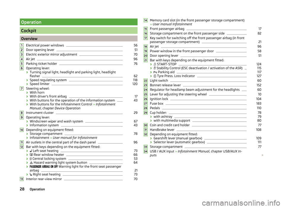
OverviewElectrical power windows
56
Door opening lever
51
Electric exterior mirror adjustment
70
Air jet
96
Parking ticket holder
76
Operating lever:
› Turning signal light, headlight and parking light, headlight
flasher
62
› Speed regulating system
118
›Speed limiter
120
Steering wheel:
› With horn
› With driver’s front airbag
17
›With buttons for the operation of the information system
43
›With buttons for the Infotainment Control
» Infotainment
Manual , chapter Device Operation
Instrument cluster
29
Operating lever: › Windscreen wiper and wash system
67
›Information system
43
Depending on equipment fitted:
› Storage compartment
78
›Infotainment
» User manual for Infotainment
Air outlets in the central part of the dash panel
96
Bar with keys depending on the equipment fitted: ›
Left seat heating
73
›
Rear window heater
66
›
Central locking system
53
›
Hazard warning light system button
64
›
Warning light for the front seat passenger
airbag
21
›
Right seat heating
73
Interior rear-view mirror
7012345678910111213Memory card slot (in the front passenger storage compartment)
» User manual Infotainment
Front passenger airbag17
Storage compartment on the front passenger side
82
Key switch for switching off the front passenger airbag (in front
passenger storage compartment)
21
Air jet
96
Power window in the front passenger door
58
Door opening lever
51
Bar with keys depending on the equipment fitted:
›
START-STOP
124
›
Stability Control (ESC deactivation / activation of the ASR)
115
›
Parking aid
117
›
Tyre Press. Loss Indicator
127
Light switch
60
Bonnet release lever
152
Regulator for headlamp beam adjustment for the headlights
60
Lever for adjusting the steering wheel
10
Ignition lock
104
Fuse box
183
Pedals
110
Cup holder:
78
› with ashtray
79
›with multimedia support
80
Coin and credit card holder
77
Handbrake lever
108
Depending on equipment fitted:
› Gearshift lever (manual gearbox)
109
›Selector lever (automatic gearbox)
111
Storage compartment
77
USB / AUX input
» Infotainment Manual , chapter USB/AUX In-
puts
14151617181920212223242526272829303132333428Operation
Page 35 of 216
The operating range
The engine has reached its operating temperature as soon as the pointer
moves into the middle of the scale A
» Fig. 23 . At very high ambient tempera-
tures or under heavy engine loads, the pointer may move even further to the
right.
High temperature range
The coolant temperature is too high if the pointer reaches the red area of the
scale.
Further information » page 40.
CAUTION
■
Additional headlights and other attached components in front of the air inlet
impair the cooling efficiency of the coolant.■
Never cover the radiator - there is a risk of the engine overheating.
Fuel gauge
Fig. 24
Fuel gauge: Version 1/version 2
Read and observe
on page 29 first.
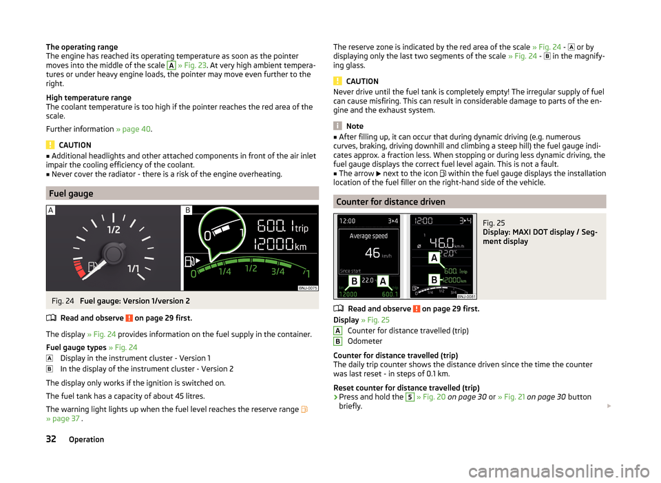
The display » Fig. 24 provides information on the fuel supply in the container.
Fuel gauge types » Fig. 24
Display in the instrument cluster - Version 1
In the display of the instrument cluster - Version 2
The display only works if the ignition is switched on.
The fuel tank has a capacity of about 45 litres.
The warning light lights up when the fuel level reaches the reserve range
» page 37 .
The reserve zone is indicated by the red area of the scale » Fig. 24 - or by
displaying only the last two segments of the scale » Fig. 24 - in the magnify-
ing glass.
CAUTION
Never drive until the fuel tank is completely empty! The irregular supply of fuel
can cause misfiring. This can result in considerable damage to parts of the en-
gine and the exhaust system.
Note
■ After filling up, it can occur that during dynamic driving (e.g. numerous
curves, braking, driving downhill and climbing a steep hill) the fuel gauge indi-
cates approx. a fraction less. When stopping or during less dynamic driving, the
fuel gauge displays the correct fuel level again. This is not a fault.■
The arrow
next to the icon
within the fuel gauge displays the installation
location of the fuel filler on the right-hand side of the vehicle.
Counter for distance driven
Fig. 25
Display: MAXI DOT display / Seg-
ment display
Read and observe on page 29 first.
Display » Fig. 25
Counter for distance travelled (trip)
Odometer
Counter for distance travelled (trip)
The daily trip counter shows the distance driven since the time the counter
was last reset - in steps of 0.1 km.
Reset counter for distance travelled (trip)
›
Press and hold the
5
» Fig. 20 on page 30 or » Fig. 21 on page 30 button
briefly.
AB32Operation
Page 43 of 216
CAUTIONIf in addition to the symbol the symbol lights up while driving, stop
driving - there is a risk of engine damage! Switch off the engine and seek as-
sistance from a specialist garage.
Coolant
Read and observe
on page 39 first.
Coolant level too low
If the coolant level is too low, the warning icon
lights up and the following
message appears in the instrument cluster display.
Please check engine coolant! Owner's Manual!
ENGINE COOLANT PLEASE CHECK
› Stop the vehicle, switch off the engine and check the coolant level
» page 156 .
› If the coolant level is too low, top up coolant
» page 156.
If the warning icon
does not illuminate after adding coolant and switching
on the engine, you may continue your journey.
If the coolant is within the specified range and the warning icon is still
lit
after switching on the ignition, then there may be a malfunction of the cooling
fan.
› Switch off the ignition.
› Check the fuse for the radiator fan, replace if necessary
» page 185, Fuses in
the engine compartment .
If the coolant level and fan fuse are OK and the Warning icon
lights up again
after switching on the ignition, do not continue driving!
Seek help from a specialist garage.
Coolant temperature too high
If the coolant temperature is too high, the warning icon
lights up and the
following message appears in the instrument cluster display.
Engine overheated. Stop! Owner's Manual!
ENGINE OVERHEAT STOP
› Stop the vehicle and turn off the engine.
› Switch on the ignition and wait until the coolant temperature returns to the
operating range » page 31.
› Continue your journey only after the warning icon
has disappeared.
WARNING■
Carefully open the coolant expansion bottle. If the engine is hot, the cool-
ing system is pressurized - risk of scalding! It is therefore best to allow the
engine to cool down before removing the cap.■
Do not touch the radiator fan. The radiator fan may switch on automati-
cally even if the ignition is off - danger of injury!
CAUTION
■ Additional headlights and other attached components in front of the air inlet
impair the cooling efficiency of the coolant.■
Never cover the radiator - there is a risk of the engine overheater.
Engine oil pressure
Read and observe
on page 39 first.
When the warning icon is
lit , the engine oil pressure is too low.
The following message is shown in the information cluster display. Oil pressure: Stop! Owner's Manual!
STOP VEHICLE OIL PRESSURE
›
Stop the vehicle, switch off the engine, and check the engine oil level
» page 154 .
›
If the oil pressure is too low, top up the engine oil » page 155.
If the oil level is within the specified range and the warning icon
turns on
again after the engine is started,
do not continue driving! Switch off the en-
gine and seek assistance from a specialist garage.
CAUTION
Do not continue your journey if for some reason it is not possible to top up
the engine oil! Switch off the engine and seek assistance from a specialist ga-
rage.
Engine oil level
Read and observe
on page 39 first.
Engine oil level too low
If the warning icons and
are
lit, the engine oil level is too low.
40Operation
Page 63 of 216
Lights and visibility
Lights
Introduction
This chapter contains information on the following subjects:
Operating the lights
60
Daylight running lights (DAY LIGHT)
61
Turn signal and main beam
62
Automatic driving lamp control
62
Fog lights
63
Fog lights with the CORNER function
63
Rear fog light
63
COMING HOME / LEAVING HOME
63
Hazard warning light system
64
Parking lights
65
Driving abroad
65
The lights work only with the ignition on, unless otherwise stated.
The layout of the controls on right-hand drive vehicles differs partially from
that shown in » Fig. 41 on page 60 . The symbols which mark the positions of
the controls are identical.
Keep the headlights lenses clean. The following guidelines must be observed
» page 144 , Headlight glasses .
WARNING■
The activation of the lights should only be undertaken in accordance with
national legal requirements.■
The driver is always responsible for the correct settings and use of the
lights.
WARNING (Continued)■ The automatic driving lamp control only operates as a support and
does not release the driver from his responsibility to check the lights and, if
necessary, to switch on the light depending on the prevailing light condi-
tions. The light sensor cannot, for example, detect rain or snow. Under
these conditions we recommend switching on the low beam or fog lights!■
Never drive with only the parking lights on! The parking lights are not
bright enough to light up the road sufficiently in front of you or to be seen
by other oncoming traffic. Therefore always switch on the low beam when
it is dark or if visibility is poor.
Note
■ The headlights may mist up temporarily. When the driving lights are switched
on, the light outlet areas are free from condensation after a short time, al-
though the headlight lenses may still be misted up around the edge. This mist
has no influence on the life of the lighting system.■
The instruments are also illuminated when the parking light, low or high
beam light is switched on. The brightness of the instrument lighting can be ac-
tivated or deactivated in the Infotainment » Operating instructions for Info-
tainment , chapter Vehicle settings (CAR button) .
Operating the lights
Fig. 41
Light switch and control dial for
headlight range adjustment
Read and observe on page 60 first.
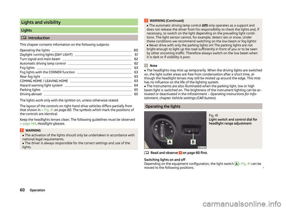
Switching lights on and off
Depending on the equipment configuration, the light switch
A
» Fig. 41 can be
moved to the following positions.
60Operation
Page 68 of 216
Parking lightsRead and observe
on page 60 first.
The parking light is designed for temporary lighting of the parked vehicle.
Switching on
the parking light
›
Switch off the ignition.
›
Place the control lever into position
A
or
B
as far as it can go » Fig. 42 on
page 62 - the parking light on the right/left-hand side of the vehicle is
switched on.
If the right or left turn signal light has been switched on and the ignition is
switched off, the parking light is not automatically switched on.
Switching on the parking lights on both sides
›
Turn the light switch
A
to position
» Fig. 41 on page 60 and lock the vehi-
cle.
After pulling out the ignition key and opening the driver's door, an audible
warning sounds. After a few seconds or after closing the driver's door, the au-
dible alarm is turned off, but the parking lights will remain switched on.
CAUTION
Turning on the parking light means the battery is heavily loaded, especially
over short distances.
Driving abroad
Read and observe
on page 60 first.
The low beam is set asymmetrically. It illuminates the side of the road on
which the vehicle is being driven to a greater extent.
When driving in countries with opposing traffic system (traffic on the left/
right), asymmetric headlight adjustment can dazzle oncoming traffic. To pre-
vent oncoming traffic from being dazzled, the headlights must be adjusted by
a specialist garage.
Note
For more information on adjusting the headlights, consult a specialist garage.Interior lights
Introduction
This chapter contains information on the following subjects:
Front interior light
65
Rear interior light
66
Note
The light turns off automatically 10 minutes after switching off the ignition or
opening a door unless otherwise specified
Front interior light
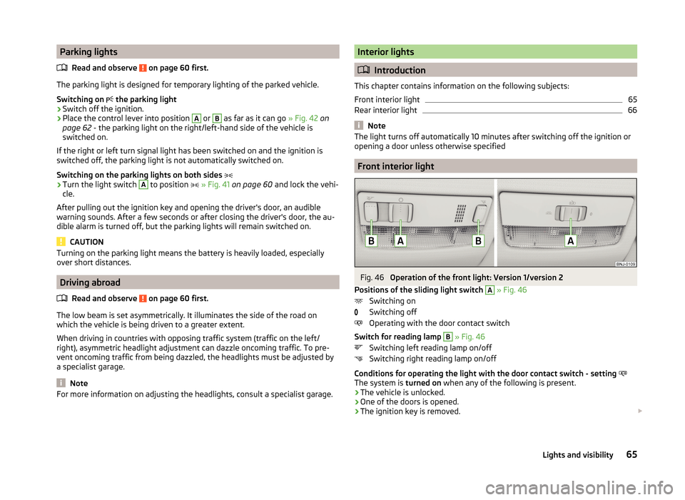
Fig. 46
Operation of the front light: Version 1/version 2
Positions of the sliding light switch
A
» Fig. 46
Switching on
Switching off
Operating with the door contact switch
Switch for reading lamp
B
» Fig. 46
Switching left reading lamp on/off
Switching right reading lamp on/off
Conditions for operating the light with the door contact switch - setting
The system is turned on when any of the following is present.
› The vehicle is unlocked.
› One of the doors is opened.
› The ignition key is removed.
65Lights and visibility
Page 72 of 216
Automatic wiping/washing for the windscreen
The wash system operates immediately, the windscreen wipers wipe some-
what later. The wash system and the windscreen wiper operate simultaneous-
ly at a speed of more than 120 km/h.
Letting go of the operating lever will cause the windscreen wash system to
stop and the wipers to continue for another 1 to 3 wiper strokes (depending on
the spraying duration).
Automatic wiping/washing for the rear window
The wash system operates immediately, the wiper wipes somewhat later.
Letting go of the operating lever will cause the windscreen wash system to
stop and the wiper to continue for another 2 to 3 wiper strokes (depending on
the spraying duration). The operating lever remains in position 6
.
Winter setting of the windscreen wiper
If the windscreen wipers are in rest position, they cannot be folded out from
the windscreen. For this reason we recommend adjusting the windscreen wip-
ers in winter so that they can be folded out from the windscreen easily.
› Switch on the windscreen wipers.
› Switch off the ignition.
The windscreen wipers remain in the position in which they were when
switching off the ignition.
The service position can also be used as a winter position » page 181, Replac-
ing the windscreen wiper blades .
Note
■
If the operating lever is in the position 2 or 3 and the speed of the vehicle
drops below 4 km/h, the wiping speed is switched to a lower wiping level. The
original setting is restored step by step when the speed of the vehicle exceeds
8 km/h.■
The rear window is wiped once automatically if the windscreen wipers are on
when reverse gear is selected. The function can be activated/deactivated in
the Infotainment system » Infotainment user manual , chapter Vehicle settings
(CAR button) .
Headlight cleaning system
Read and observe
and on page 68 first.
After the ignition is switched on the headlights are always cleaned at the first
and after every tenth spray of the windscreen (setting
5
» Fig. 51 on page 68 ),
when the low beam is switched on.
You should remove stubborn dirt (such as insect residues) from the headlight
lenses at regular intervals, for example when refuelling. The following guide-
lines must be observed » page 144, Headlight glasses .
To ensure the proper operation of the cleaning system during the winter, any
snow should be removed from the washer nozzle fixtures and ice should be
cleared with a de-icing spray.
CAUTION
Never remove the nozzles from the headlight cleaning system by hand – risk of
damage.
Note
The headlamp cleaning system works at an ambient temperature of about -12 °
C to + 39 ° C.
Rear mirror
Introduction
This chapter contains information on the following subjects:
Interior mirror
70
Exterior mirrors
70WARNING■ Make sure that the mirror is not covered by ice, snow, condensation or
other objects.■
Convex (curved outward) or aspherical exterior mirrors increase the field
of vision. They do, however, make objects appear smaller in the mirror.
These mirrors are therefore only of limited use for estimating distances to
the following vehicles.
■
Whenever possible use the interior mirror for estimating the distances to
the following vehicles.
69Lights and visibility
Page 137 of 216

Distance of the load center of gravityfrom the ball headPermissible total weight of the ac-cessories, including load0 cm50 kg30 cm50 kg60 cm25 kg70 cm0 kgWARNING■Never exceed the permissible gross weight of the accessory including
load - there is a risk of damaging the ball head of the towing device.■
Never exceed the permissible protrusion of the ball head including towing
device - there is a risk of damaging the ball head of the towing device.
Note
We recommend that you use the accessories from ŠKODA Original Accessories.
Trailer
Introduction
This chapter contains information on the following subjects:
Trailer, connect and disconnect
134
Loading a trailer
135
Towing a trailer
135
Anti-theft alarm system
136
If your vehicle has already been factory-fitted with towing equipment or is fit-
ted with towing equipment from ŠKODA Original Accessories, then it meets all
of the technical requirements and national legal provisions for towing a trailer.
Note
If there is an error in the trailer lighting system, check the fuses in the fuse box
in the dashboard » page 183.Trailer, connect and disconnectFig. 141
13-pin socket, and safety eye
Coupling
›
Fit the ball rod.
›
Lift off protective cap
3
» Fig. 129 on page 129 upwards.
›
Place the trailer onto the ball head.
›
Insert the trailer cable into the 13-pin socket
A
» Fig. 141.
If the trailer that is to be towed has a 7-pin connector, you can make an elec-
trical connection using a suitable adapter from ŠKODA Original Accessories.
›
Hook the breakaway cable of the trailer to the security lock slot
B
.
The breakaway cable of the trailer has to sag when mounted into the security
lock slot for all trailer positions relative to the vehicle (sharp curves, reverse
driving and the like.)
Detaching
›
Unhook the breakaway cable of the trailer from the securing eyelet
B
» Fig. 141 .
›
Pull the trailer cable out of the 13-pin socket.
›
Remove the trailer from the ball head.
›
Place cap
3
onto the ball head » Fig. 129 on page 129 .
Exterior mirrors
You have to have additional exterior mirrors fitted if you are not able to see
the traffic behind the trailer with the standard rear-view mirrors. National legal
requirements must be observed.
Headlights
The front of the vehicle can be lifted when a trailer is being towed and the
headlights can dazzle other road users.
Adjust the headlight setting on the headlight range control » page 60, Operat-
ing the lights .
134Driving
Page 147 of 216

■Never remove snow or ice from glass parts using warm or hot water – there
is a risk of cracking in glass.■
Make sure that when removing snow and ice from the windows, the labels
attached to the vehicle by the factory are not damaged.
CAUTION
Information for cleaning windows■Do not clean the inside of the windows with sharp-edged objects or corro-
sive and acidic cleaning agents – there is a risk of damaging the heating ele-
ments or window aerial.■
When drying the windows after washing the vehicle, do not use window
leathers that have been used to polish the bodywork. Residues of preserva-
tives in the chamois leather can smear the windows and reduce visibility.
Headlight glasses
Read and observe
and on page 142 first.
Clean the plastic headlight lenses with clean, warm water and soap.
CAUTION
■The headlights are never to be wiped dry - there is a risk of damaging the
protective lacquer and the headlight glass subsequently developing cracks.■
Do not use sharp objects to clean the glasses - there is a risk of damaging
the protective lacquer and the headlight glasses subsequently developing
cracks.
■
Do not use any aggressive cleaning or chemical solvent products to clean the
headlights – risk of damaging the headlight lenses.
Door closing cylinder
Read and observe
and on page 142 first.
Specific products must be used for de-icing door lock cylinders.
CAUTION
Make sure that as little water as possible gets into the locking cylinder when
washing the vehicle - there is a risk of freezing the lock cylinder!Cavity protection
Read and observe
and on page 142 first.
All the cavities of your vehicle which are at risk from corrosion are protected
for life by a layer of protective wax applied in the factory.
Wax protection does not require to be inspected or re-treated.
If any small amount of wax flow out of the cavities at high temperatures, these
must be removed with a plastic scraper and the stains cleaned using a petrole-
um cleaner.
WARNINGSafety regulations should be observed when using petroleum cleaner to re-
move wax – there is a risk of fire.
Jack
Read and observe
and on page 142 first.
The jack is maintenance-free.
If necessary, the moving parts of the jack should be lubricated with a suitable
lubricant.
Wheels
Read and observe
and on page 142 first.
Wheel rims
Also thoroughly wash the wheel rims when washing the vehicle on a regular
basis.
Regularly remove salt and brake dust otherwise the rim material will be at-
tacked.
Light alloy wheels
After washing thoroughly and treat the wheel rims with a protective product
for light alloy wheels.
For the treatment of wheel rims do not use products which may cause damage
to the paint on the rims.
144General Maintenance
Page 156 of 216
Radiator fanRead and observe
and on page 151 first.
The radiator fan is powered by an electric motor. Operation is controlled ac-
cording to the temperature of the coolant.
WARNINGThe fan can intermittently continue to run for approximately 10 minutes af-
ter the ignition is switched off.
Windscreen washer system
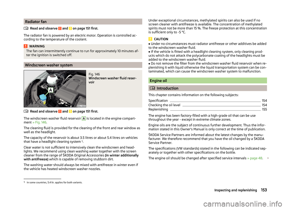
Fig. 146
Windscreen washer fluid reser-
voir
Read and observe and on page 151 first.
The windscreen washer fluid reservoir
A
is located in the engine compart-
ment » Fig. 146 .
The cleaning fluid is provided for the cleaning of the front and rear window as
well as the headlight.
The capacity of the reservoir is about 3.5 litres or about 5.4 litres on vehicles
that have a headlight cleaning system 1)
.
Clear water is not sufficient to intensively clean the windscreen and head-
lights. We recommend using clean washing water together with the screen
cleaner from the range of ŠKODA Original Accessories (in winter additionally
with antifreeze) which is capable of removing stubborn dirt.
The washing water should always be mixed with antifreeze in winter even if
the vehicle has heated windscreen washer nozzles.
Under exceptional circumstances, methylated spirits can also be used if no
screen cleaner with antifreeze is available. The concentration of methylated
spirits must not be more than 15 %. The freeze protection at this concentration
is sufficient only to -5 °C.
CAUTION
■ Under no circumstances must radiator antifreeze or other additives be added
to the windscreen washer fluid.■
If the vehicle is fitted with a headlight cleaning system, only cleaning prod-
ucts which do not attack the polycarbonate coating of the headlights must be
added to the windscreen washer fluid.
■
Do not remove the filter from the windscreen washer fluid reservoir when re-
plenishing it with liquid otherwise the liquid transportation system can be con-
taminated, which can cause the windscreen washer system to malfunction.
Engine oil
Introduction
This chapter contains information on the following subjects:
Specification
154
Checking the oil level
154
Replenishing
155
The engine has been factory-filled with a high-grade oil that can be use
throughout the year - except in extreme climate zones.
Engine oils are the subject of continuous further development. Thus the infor-
mation stated in this Owner's Manual is only correct at the time of publication.
ŠKODA Service Partners are informed about the latest changes by the manu-
facturer. We therefore recommend that you have the oil changed by a ŠKODA
Service Partner.
The specifications (VW standards) stated in the following can be indicated sep-
arately or together with other specifications on the bottle.
The engine oil should be changed after specified service intervals » page 48.
1)
In some countries, 5.4 ltr. applies for both variants.
153Inspecting and replenishing
Page 158 of 216
CAUTION■The oil level must never be above the range A » Fig. 147 - risk of damage to
the motor as well as the exhaust system!■
If for some reason, it is not possible to top up the engine oil under the cur-
rent circumstances,
do not continue driving! Switch off the engine and seek
assistance from a specialist garage.
■
If the oil level is above the range
A
,
do not continue to drive! Switch off
the engine and seek assistance from a specialist garage.
Replenishing
Read and observe
and on page 154 first.
›
Unscrew the cap of the engine oil filler opening » Fig. 145 on page 152 .
›
Replenish the oil in portions of 0.5 litres in accordance with the correct speci-
fications » page 154 .
›
Check the oil level » page 154.
›
Screw the lid of the engine oil filler closed carefully.
›
Pull the dipstick out as far as the stop.
Coolant
Introduction
This chapter contains information on the following subjects:
Checking the coolant level
156
Replenishing
156
The coolant provides cooling for the motor.
It consists of water and coolant additive with additives that protect the cooling
system against corrosion and prevents furring.
The coolant additive level in the coolant must amount to at least 40%.
The coolant additive may be increased to a maximum of 60%.
The correct mixing ratio of water and coolant additive is to be checked if nec-
essary by a specialist garage or is to be restored if necessary.
The description of the coolant is shown in the coolant expansion reservoir
» Fig. 148 on page 156 .
WARNINGThe engine compartment of your car is a hazardous area. While working in
the engine compartment, be sure to observe the following warnings
» page 150 .■
The coolant is harmful to health.
■
Avoid contact with the coolant.
■
Coolant vapours are harmful to health.
■
Never open the end cover of the coolant expansion reservoir while the
engine is still warm. The cooling system is pressurized!
■
When opening the end cover of the coolant expansion reservoir, cover it
with a cloth to protect your face, hands and arms from hot steam or hot
coolant.
■
If any coolant splashes into your eyes, immediately rinse out your eyes
with clear water and contact a doctor as soon as possible.
■
Always keep the coolant in the original container safe from people who
are not completely independent, especially children - there is a danger of
poisoning!
■
Consult a doctor immediately if coolant is swallowed.
■
Never spill operating fluids over the hot engine - risk of fire.
CAUTION
■ Do not continue if for some reason it is not possible to fill with coolant un-
der the current circumstances! Switch off the engine and seek assistance from
a specialist garage.■
With an empty expansion tank top up coolant. The system could ventilate -
there is a risk of engine damage,
not continue! Switch off the engine and
seek assistance from a specialist garage.
■
The amount of coolant additive in the coolant must never be allowed to fall
below 40 %.
■
Over 60 % coolant additive in the coolant reduces the antifreeze protection
and coolant effectiveness.
■
A coolant additive that does not comply with the correct specification can
significantly reduce the corrosion protection of the cooling system.
■
Any faults resulting from corrosion may cause a loss of coolant and can con-
sequently result in major engine damage!
■
Do not fill the coolant above the mark
A
» Fig. 148 on page 156 .
■
If an error occurs, leading to the engine overheating, the help of a professio-
nal garage is to be sought - there is a risk of serious engine damage occurring.
■
Additional headlights and other attached components in front of the air inlet
impair the cooling efficiency of the coolant.
■
Never cover the radiator - there is a risk of the engine overheating.
155Inspecting and replenishing