trailer SKODA FABIA 2016 3.G / NJ User Guide
[x] Cancel search | Manufacturer: SKODA, Model Year: 2016, Model line: FABIA, Model: SKODA FABIA 2016 3.G / NJPages: 196, PDF Size: 31.86 MB
Page 116 of 196

Overtaking and towingRead and observe
on page 110 first.
When overtaking
When your vehicle is being controlled at a speed that is lower than the set
speed and the turn signal is operated, ACC assesses this situation as meaning
that the driver wishes to overtake. The ACC automatically accelerates the vehi-
cle, thereby reducing the proximity to a vehicle ahead.
If your vehicle changes to the overtaking lane and no vehicle is detected
ahead, ACC accelerates until the set speed is reached and then keeps it con-
stant.
Acceleration can be cancelled at any time by touch on the brake pedal or
pressing the button on the lever
» Fig. 142 on page 111 .
Towing a trailer
When towing, or if another accessory is connected to the trailer socket, ACC control is set with a lower rate. The manner of driving should therefore be
adapted to this limitation.
Malfunctions
Read and observe
on page 110 first.
If, for some unknown reason, ACC is not available, the warning light appears
in the display of the instrument cluster and an appropriate message is shown.
Sensor covered / dirty
If the sensor is dirty or covered, a message indicating that there is no sensor
view appears. Clean the sensor cover or remove the obstacles » Fig. 125 on
page 100 .
ACC not available
If the ACC is currently unavailable, a message concerning the unavailability ap-
pears. Stop the vehicle, switch off the engine and then start it again. If ACC
continues to be unavailable, seek the assistance of a specialist garage.
ACC fault
With an ACC fault, an error message appears. Seek help from a specialist ga-
rage.
Front Assist
Introduction
This chapter contains information on the following subjects:
Operation
114
Distance warning
115
Warning and automatic braking
115
Deactivation/activation
116
Malfunctions
116
The Front Assist (hereinafter referred to as "system") warns you of the danger
of a collision with a vehicle or another obstacle in front of the vehicle, and tries
to avoid a collision or mitigate its consequences by automatically applying the
brakes where necessary.
The area in front of the vehicle is monitored by a radar sensor » page 100.
WARNING■
The general information relating to the use of assistance systems must
be observed » page 100, in section Introduction .■
The system does not respond to crossing or oncoming objects.
CAUTION
In case of failure of more than one brake light on the vehicle or on the electri-
cally connected trailer, the system becomes unavailable.
Operation
Read and observe
and on page 114 first.
The system support is provided in the following manner.▶ Alerts you about a dangerous proximity to the vehicle ahead.
▶ Warns you of an impending collision.
▶ Assists with a brake action triggered by the driver.
▶ If the driver fails to respond to a detected danger, an automatic braking ac-
tion is performed.
The system can work only if the following basic conditions are met. The system is activated.
TCS is activated » page 102.
The vehicle is travelling forwards at a speed of more than approx. 5 km/h.
114Driving
Page 121 of 196

Towing device and trailer
Hitch
Introduction
This chapter contains information on the following subjects:
Description
119
Adjusting the ready position
120
Check the setting of the standby position
120
Assembling the bar ball - Step 1
120
Assembling the bar ball - Step 2
121
Check proper fitting
121
Removing the bar ball - Step 1
122
Removing the bar ball - Step 2
122
Vertical load with mounted accessories
123
The maximum trailer nose weight when towing a trailer is 50 kg. Other data
(e.g. shown onthe nameplate of the hitch) on provides information about the
test values of the device .
WARNING■ Check that the ball head is seated correctly and is secured in the mount-
ing recess before starting any journey.■
When the knee-joint bar is not used and properly secured in the receiving
shaft, it is damaged or incomplete, this must not be used - there is a risk of
an accident.
■
Do not modify or adapt the towing equipment in any way.
■
Keep the mounting recess of the towing equipment clean at all times.
Such dirt prevents the ball head from being attached securely.
DescriptionFig. 150
Carrier for the towing device / tow bar
Read and observe
on page 119 first.
The knee-joint bar is detachable and is located in the storage compartment for
the spare / emergency wheel.
Support for the towing device and tow bar » Fig. 150
Cover for the mounting recess
Mounting recess
Dust cap
Ball head
Operating lever
Lock cap
Release pin
Key
Locking ball
123456789119Towing device and trailer
Page 123 of 196

Fig. 155
Insert ball rod / trigger bolt in the extended state
Read and observe
on page 119 first.
The tow bar must be set to the standby position » page 120.
Preparing installation
›
Remove the cover cap
A
in the direction of arrow
1
» Fig. 154 using the on-
board tool clamp for pulling off the wheel trims.
›
Remove cover cap
B
in the direction of arrow
2
» .
Fitting
›
Grip the tow bar from underneath » Fig. 155 and insert into the mounting re-
cess in arrow direction
3
until you hear it click into place » .
The operating lever
C
automatically turns upwards in the direction of arrow
4
and the release pin
D
pops out (both its red and green parts are visible)
» .
If the operating lever
C
does not turn automatically, or if the release pin
D
does not pop out, remove the tow bar from the mounting recess by turning the
operating lever
C
downwards as far as it can go. Clean the contact surfaces
on the tow bar and the mounting recess.
WARNING■ Carefully remove the cap for the mounting recess B - there is a risk of
hand injury.■
Keep your hands outside the operating lever's range of motion when at-
taching the ball head – there is a risk of finger injury.
■
Never attempt to pull the operating lever upwards forcibly to turn the
key. Doing so would mean the ball head is not attached correctly.
Assembling the bar ball - Step 2Fig. 156
Secure the lock and remove key / place cap on lock
Read and observe
on page 119 first.
›
Turn the key
A
in the direction of arrow
1
so that the green marking points
upwards » Fig. 156 .
›
Remove the key in the direction of the arrow
2
.
›
Fit and press in the cap
B
on the hand-wheel lock in the direction of the ar-
row
3
.
›
Check the ball head for secure mounting » page 121, Check proper fitting .
Check proper fitting
Fig. 157
Correctly secured ball head
Read and observe on page 119 first.
Correctly secured ball rod » Fig. 157
The ball head does not come out of the mounting recess even after heavy
“shaking”.
Operating lever
A
is located as far up as possible.
121Towing device and trailer
Page 124 of 196

The release pin B is completely exposed (both its red and green parts are
visible).
The key is removed and the cap C
attached to the lock.
Removing the bar ball - Step 1
Fig. 158
Remove the cap from the lock
Fig. 159
Insert the key into the lock / unlock the lock
Read and observe
on page 119 first.
No trailer or other accessory is connected to the tow bar. We recommend put- ting the protective cover onto the ball head before removing the tow bar.
›
Remove the cover
A
from the lock in the direction of the arrow
1
» Fig. 158 .
›
Insert the key
B
into the lock in the direction of arrow
2
, so that its green
marker points upward » Fig. 159.
›
Turn the key in the direction of arrow
3
so that the red marking points up-
wards.
Removing the bar ball - Step 2Fig. 160
Release tow bar
Read and observe on page 119 first.
Removing
›
Grasp the ball head from underneath » Fig. 160 .
›
Push in the release bolt
A
in the direction of arrow
1
until it stops and si-
multaneously press the operating lever
B
in the direction of arrow
2
until it
stops.
The ball head is released in this position and falls freely into the hand. If it
does not fall freely into the hand, use your other hand to push it upwards.
Subsequent steps
›
Insert the cover
B
» Fig. 154 on page 120 in the opposite direction to arrow
2
.
›
Fix the cap
A
» Fig. 154 on page 120 aligning it with “check mark” in the low-
er bumper area.
›
Push the cap in first on the left and right and then at the top.
If the operating lever
B
is held firm and not pushed downwards as far as it
can go, it will go back up after the ball head is removed and will not latch into
the ready position. The knee-joint bar will then need to be brought into this
position before the next time it is installed » page 120, Adjusting the ready po-
sition .
The knee-joint bar must be cleaned before storing in the box with the vehicle
tool always.
WARNINGNever allow the ball head to remain unsecured in the boot. This could
cause damage to the boot upon sudden braking, and could put the safety
of the occupants at risk! 122Driving
Page 125 of 196

CAUTION■Place the tow bar in the standby position, with the key upwards, and store in
the box - otherwise there is a risk of damage to the key!■
Do not use excessive force when handling the operating lever (e.g. do not
step on it).
Vertical load with mounted accessories
Fig. 161
Representation of the maximum
length of the mounted accesso-
ries and the permissible total
weight of the accessory depend-
ing on the load centre of gravity
Read and observe on page 119 first.
When using the accessories (e.g. bicycle carrier), the maximum length and the
permissible total weight including load must be considered.
The maximum length of the mounted accessories (from the ball of the towing
device) is 70 cm » Fig. 161 .
The total permitted weight of the accessories including load changes with in-
creasing distance of the load centre of gravity from the ball head of the towing
device.
Distance of the load centre of gravity from the ball headPermissible total weight of the ac-cessories, including load0 cm50 kg30 cm50 kg60 cm25 kg70 cm0 kg
CAUTION
Never exceed the permissible total weight of the accessories incl. load and
maximum length of the accessories - risk of damage to the towing device.NoteWe recommend that you use the accessories from ŠKODA Original Accessories.
Using hitch
Trailer (accessory) connect and disconnect
Fig. 162
Housing of the 13 pin socket,
safety eyelet
Connect and disconnect
›
Install the ball bar and the remove the protective cap
3
» Fig. 150 on page 119
lose weight.
›
Place the trailer (the accessory) onto the tow ball.
›
Plug the trailer cable into 13-pin socket
A
» Fig. 162 . (If the trailer / accesso-
ries have a 7-pin connector, use a corresponding reduction piece from the
ŠKODA Original Accessories).
›
Suspend the breakaway cable of the trailer at the safety eyelet
B
(the
breakaway cable must sag in all trailer settings in view of the vehicle).
Uncoupling takes place in reverse order.
Exterior mirrors
You should have additional exterior mirrors fitted if you are not able to see the
traffic behind the trailer using the standard rear-view mirrors.
Headlights
The front of the vehicle may lift up when a trailer (accessory) is being towed
and the headlights may dazzle other road users. Set the range of the head-
lights » page 53 , Operating the lights .
Power supply of the trailer / accessory power system
In the electrical connection between the vehicle and trailer (accessory), the
trailer (accessories) is supplied with power from the vehicle (with ignition
switched on and off).
123Towing device and trailer
Page 126 of 196
With the engine switched off, the vehicle battery is discharged by the connec-
ted consumers.
At low charge state of the vehicle battery, the power supply to the trailer (ac-
cessories) is interrupted.WARNING■ An improperly connected electrical installation of the trailer (accessories)
may result in an accident or serious injury from electrical shock.■
Do not make any adjustments to the electrical installation of the vehicle
and the trailer (accessories) - risk of an accident or serious injury from elec-
trical shock.
■
After the electrical connection between the vehicle and trailer (accessory)
the trailer / accessory lights should be checked for function.
■
Never use the securing eye to tow - The is a risk of accident!
CAUTION
■ An improperly connected electrical installation of the trailer (accessories) can
lead to the inoperability of the vehicle electronics.■
The total power consumption of all the connected loads to the trailer power
supply must not exceed 350 watts, otherwise there is a risk of damage to the
electrical system of the vehicle.
Loading a trailer
Correct the tyre inflation pressure on the vehicle for “full load” » page 146.
Distribution of the cargo
Distribute the cargo in the trailer in such a way that heavy items are located as
close to the trailer axle as possible. Secure the load from slipping.
The distribution of the weight is very poor if your vehicle is unladen and the
trailer is laden. Nevertheless, maintain a particularly low speed if you cannot
avoid driving with this combination.WARNINGAn unsecured load can adversely affect stability and driving safety signifi-
cantly - there is a risk of accident!
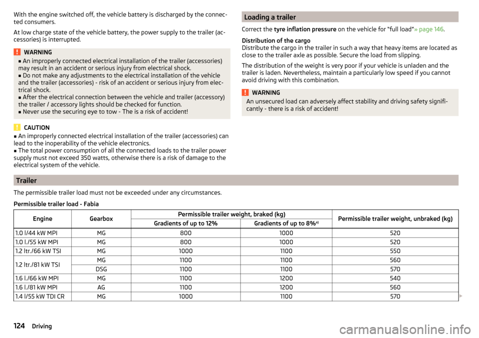
Trailer
The permissible trailer load must not be exceeded under any circumstances.Permissible trailer load - FabiaEngineGearboxPermissible trailer weight, braked (kg)Permissible trailer weight, unbraked (kg)Gradients of up to 12%Gradients of up to 8% a)1.0 l/44 kW MPIMG80010005201.0 l./55 kW MPIMG80010005201.2 ltr./66 kW TSIMG100011005501.2 ltr./81 kW TSIMG11001100560DSG110011005701.6 l./66 kW MPIMG110012005401.6 l./81 kW MPIAG110012005601.4 l/55 kW TDI CRMG10001100570
124Driving
Page 127 of 196
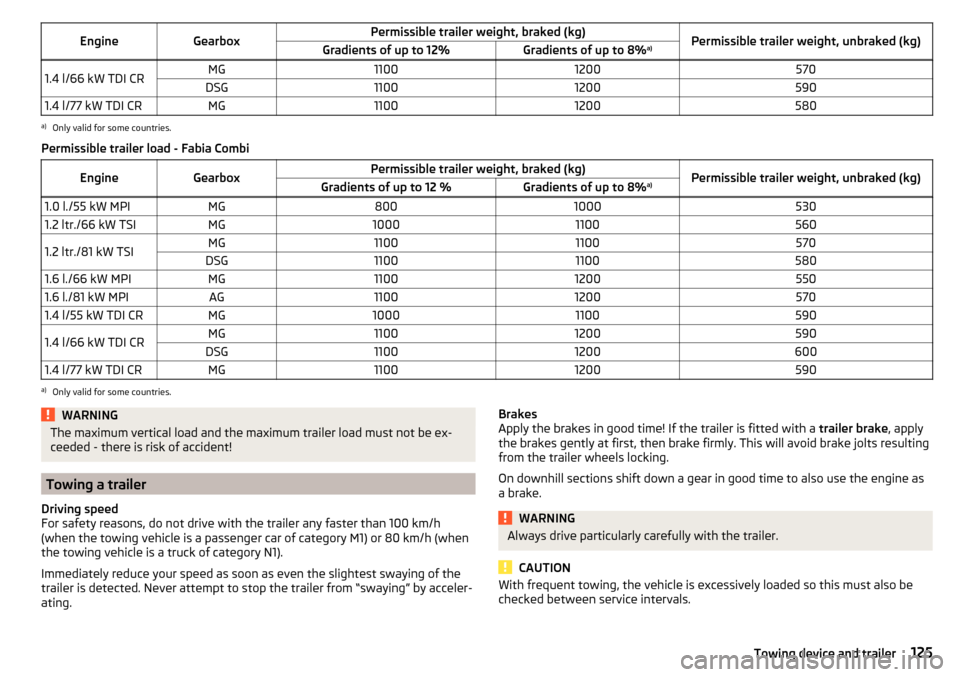
EngineGearboxPermissible trailer weight, braked (kg)Permissible trailer weight, unbraked (kg)Gradients of up to 12%Gradients of up to 8%a)1.4 l/66 kW TDI CRMG11001200570DSG110012005901.4 l/77 kW TDI CRMG11001200580a)
Only valid for some countries.
Permissible trailer load - Fabia Combi
EngineGearboxPermissible trailer weight, braked (kg)Permissible trailer weight, unbraked (kg)Gradients of up to 12 %Gradients of up to 8% a)1.0 l./55 kW MPIMG80010005301.2 ltr./66 kW TSIMG100011005601.2 ltr./81 kW TSIMG11001100570DSG110011005801.6 l./66 kW MPIMG110012005501.6 l./81 kW MPIAG110012005701.4 l/55 kW TDI CRMG100011005901.4 l/66 kW TDI CRMG11001200590DSG110012006001.4 l/77 kW TDI CRMG11001200590a)
Only valid for some countries.
WARNINGThe maximum vertical load and the maximum trailer load must not be ex-
ceeded - there is risk of accident!
Towing a trailer
Driving speed
For safety reasons, do not drive with the trailer any faster than 100 km/h
(when the towing vehicle is a passenger car of category M1) or 80 km/h (when
the towing vehicle is a truck of category N1).
Immediately reduce your speed as soon as even the slightest swaying of the
trailer is detected. Never attempt to stop the trailer from “swaying” by acceler-
ating.
Brakes
Apply the brakes in good time! If the trailer is fitted with a trailer brake, apply
the brakes gently at first, then brake firmly. This will avoid brake jolts resulting
from the trailer wheels locking.
On downhill sections shift down a gear in good time to also use the engine as
a brake.WARNINGAlways drive particularly carefully with the trailer.
CAUTION
With frequent towing, the vehicle is excessively loaded so this must also be
checked between service intervals.125Towing device and trailer
Page 128 of 196
Anti-theft alarm system
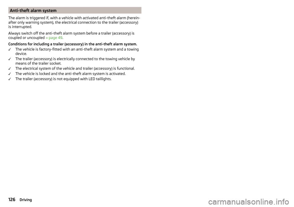
The alarm is triggered if, with a vehicle with activated anti-theft alarm (herein-
after only warning system), the electrical connection to the trailer (accessory)
is interrupted.
Always switch off the anti-theft alarm system before a trailer (accessory) is
coupled or uncoupled » page 49.
Conditions for including a trailer (accessory) in the anti-theft alarm system. The vehicle is factory-fitted with an anti-theft alarm system and a towing
device.
The trailer (accessory) is electrically connected to the towing vehicle by
means of the trailer socket.
The electrical system of the vehicle and trailer (accessory) is functional.
The vehicle is locked and the anti-theft alarm system is activated.
The trailer (accessory) is not equipped with LED taillights.126Driving
Page 131 of 196
WARNING■No changes may be made to airbag system components, the front bump-
er and the bodywork.■
Any work on the airbag system including the installation and removal of
system components due to other repair work (e.g. removal of the steering
wheel) must only be carried out by a specialist garage.
■
Do not manipulate individual parts of the airbag system, as this might re-
sult in the airbag being deployed.
■
If the airbag has been deployed, the airbag system must be replaced.
WARNINGThe airbag system operates using pressure sensors located in the front
doors. For this reason, no adjustments may be carried out to the doors or
door panels (e.g. installation of additional loudspeakers). Resulting damage
can impair the functioning of the airbag system - risk of accidents and fatal
injuries! The following guidelines must therefore be observed.■
Any work on the front doors and their door panels must be carried out by
a specialist garage.
■
Never drive the vehicle with the inner door panels removed or with open-
ings in the panelling.
Acceptance and recycling of used vehicles
Read and observe
on page 127 first.
All new ŠKODA vehicles are 95% recyclable.
Service intervals
Introduction
This chapter contains information on the following subjects:
Overview of service intervals
130
Fixed service intervals QI1 - QI4
130
Variable service interval QI6
130
Digital Service Plan
131
The service interval display in the display of the instrument cluster will remind
you to carry out every service stipulated by the manufacturer at the right time
in order to prevent you from forgetting any » page 41.
The completion of services can be verified through the printed verification
from the digital service schedule and the respective receipts.
The specified service intervals are tailored to normal operating conditions.
In the case of aggravated operating conditions, it will be necessary to have
some service work carried out before the date of the next regular service or
between the specified service intervals. This applies mainly to the cleaning or
the replacement of the air filter insert in regions with heavy dust pollution as
well as checking and replacing the toothed belt, but also to vehicles with die-
sel particle filters, which can put greater strain on the engine oil.
The following is taken to mean aggravated operating conditions: ▶ Fuel containing sulphur.
▶ Frequent short trips.
▶ Longer periods of engine idling (e.g. taxis).
▶ Operation in areas with heavy dust pollution.
▶ Frequent trailer operation.
▶ Predominantly stop-and-go traffic as is e.g. often the case in city driving.
▶ Operation predominantly during winter.
You will be told at the specialist garage whether the operating conditions of your vehicle may make it necessary for service work to be carried out between
the normal service intervals.
Different service charges may apply according to the particular scope of work
required, the vehicle type and specification, and your vehicle’s condition.
Note
■ The customer is responsible for covering the cost of all services including
changing or replenishing the oil, even during the warranty period, unless sta-
ted otherwise in the ŠKODA AUTO warranty terms or other agreements.■
You will be informed about the service checks and actions at each service by
the specialist garage.
129Care and maintenance
Page 153 of 196
CAUTIONScrew the jack back to its starting position prior to putting it back in its box -
risk of damage to the box.
Note
The declaration of conformity is included with the jack or the log folder.
Changing a wheel
Preliminary work
For safety's sake, the following instructions must be observed before
changing a wheel on the road.
›
Park the vehicle as far as possible away from the traffic flow - choose a place
with a flat and firm surface.
›
Switch off the engine.
›
For vehicles with manual transmission select1, gear .
›
For vehicles with automatic transmission , place the selector lever in the P
position.
›
Firmly apply the handbrake.
›
Switch on the hazard warning lights and set up the warning triangle at the
prescribed distance.
›
Have all the occupants get out . The passengers should not stand on the
road while the wheel is being changed (they should remain behind a crash
barrier, for instance).
›
Uncouple any trailers.
Changing a wheel
›
Take out the emergency or spare wheel » page 152.
›
Remove the full wheel trim » page 152or caps» page 152 .
›
Loosen the wheel bolts » page 153 » .
›
Jack up the vehicle » page 153 until the wheel that needs changing is clear of
the ground.
›
Unscrew the wheel bolts and place them on a clean surface (cloth, paper,
etc.).
›
Remove the wheel carefully.
›
Attach the spare wheel and slightly screw on the wheel bolts.
›
Lower the vehicle.
›
Tighten the wheel bolts opposite each other using the wheel wrench (“pull- ing crossways”) » page 153.
›Replace the wheel trim
» page 152and caps» page 152 .
When fitting unidirectional tyres, ensure that the direction of rotation is cor-
rect » page 145 .
All bolts must be clean and must turn easily. If screws are corroded and diffi-
cult to move, these must be replaced.WARNING■ Undo the wheel bolts just a little (about one turn), provided the vehicle
has not yet been jacked up. Otherwise the wheel could come loose and fall
off – risk of injury.■
Under no circumstances must the bolts be greased or oiled - cause an ac-
cident.
Subsequent steps
After changing the wheel, the following work should be carried out.
›
Stow the replaced wheel in the well under the floor covering of the luggage
compartment and secure it with a nut.
›
Stow the tool kit in the space provided and secure using the strap.
›
Check tyre pressure on the mounted wheel and adjust if necessary and, with
vehicles with tyre pressure monitoring, save the tyre pressure values in the
system » page 117 .
›
Have the tightening torque of the wheel bolts checked as soon as possible.
The prescribed tightening torque is 120 Nm.
Change the damaged wheel or consult a specialist garage about repair possi-
bilities.
WARNINGTightening torque which is too high can damage the threads and this can
result in permanent deformation of the contact surfaces on the rim. Where
tightening torque is too low, the wheels may become loose while driving -
risk of accident. Therefore drive cautiously and only at a moderate speed
until the tightening torque has been checked.151Emergency equipment, and self-help