trailer SKODA FABIA 2016 3.G / NJ Owner's Guide
[x] Cancel search | Manufacturer: SKODA, Model Year: 2016, Model line: FABIA, Model: SKODA FABIA 2016 3.G / NJPages: 196, PDF Size: 31.86 MB
Page 157 of 196
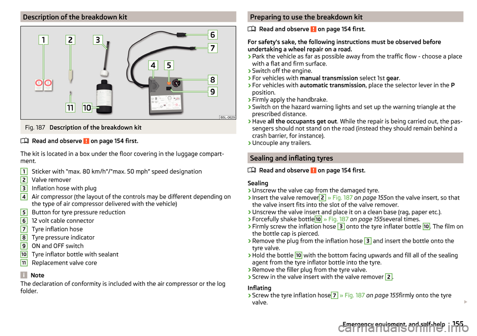
Description of the breakdown kitFig. 187
Description of the breakdown kit
Read and observe
on page 154 first.
The kit is located in a box under the floor covering in the luggage compart-
ment.
Sticker with “max. 80 km/h”/“max. 50 mph” speed designation
Valve remover
Inflation hose with plug
Air compressor (the layout of the controls may be different depending on
the type of air compressor delivered with the vehicle)
Button for tyre pressure reduction
12 volt cable connector
Tyre inflation hose
Tyre pressure indicator
ON and OFF switch
Tyre inflator bottle with sealant
Replacement valve core
Note
The declaration of conformity is included with the air compressor or the log
folder.1234567891011Preparing to use the breakdown kit
Read and observe
on page 154 first.
For safety's sake, the following instructions must be observed before
undertaking a wheel repair on a road.
›
Park the vehicle as far as possible away from the traffic flow - choose a place
with a flat and firm surface.
›
Switch off the engine.
›
For vehicles with manual transmission select 1st gear.
›
For vehicles with automatic transmission , place the selector lever in the P
position.
›
Firmly apply the handbrake.
›
Switch on the hazard warning lights and set up the warning triangle at the
prescribed distance.
›
Have all the occupants get out . While the repair is being carried out, the pas-
sengers should not stand on the road (instead they should remain behind a
crash barrier, for instance).
›
Uncouple any trailers.
Sealing and inflating tyres
Read and observe
on page 154 first.
Sealing
›
Unscrew the valve cap from the damaged tyre.
›
Insert the valve remover
2
» Fig. 187 on page 155 on the valve insert, so that
the valve insert fits into the slot of the valve remover.
›
Unscrew the valve insert and place it on a clean base (rag, paper etc.).
›
Forcefully shake bottle
10
» Fig. 187 on page 155 several times.
›
Firmly screw the inflation hose
3
onto the tyre inflater bottle
10
. The film on
the bottle cap is pierced.
›
Remove the plug from the inflation hose
3
and insert the bottle onto the
tyre valve.
›
Hold the bottle
10
with the bottom facing upwards and fill all of the sealing
agent from the tyre inflator bottle into the tyre.
›
Remove the filler plug from the tyre valve.
›
Screw in the valve insert with the valve remover
2
.
Inflating
›
Screw the tyre inflation hose
7
» Fig. 187 on page 155 firmly onto the tyre
valve.
155Emergency equipment, and self-help
Page 159 of 196
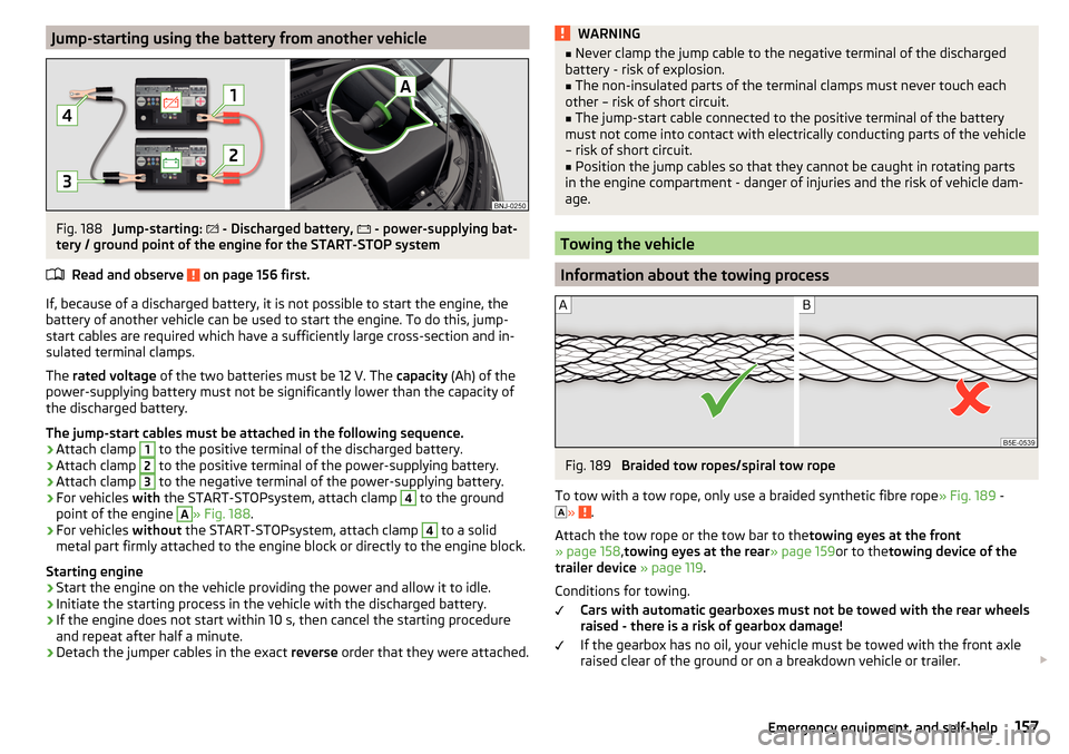
Jump-starting using the battery from another vehicleFig. 188
Jump-starting:
- Discharged battery,
- power-supplying bat-
tery / ground point of the engine for the START-STOP system
Read and observe
on page 156 first.
If, because of a discharged battery, it is not possible to start the engine, the
battery of another vehicle can be used to start the engine. To do this, jump-
start cables are required which have a sufficiently large cross-section and in-
sulated terminal clamps.
The rated voltage of the two batteries must be 12 V. The capacity (Ah) of the
power-supplying battery must not be significantly lower than the capacity of
the discharged battery.
The jump-start cables must be attached in the following sequence.
›
Attach clamp
1
to the positive terminal of the discharged battery.
›
Attach clamp
2
to the positive terminal of the power-supplying battery.
›
Attach clamp
3
to the negative terminal of the power-supplying battery.
›
For vehicles with the START-STOPsystem, attach clamp
4
to the ground
point of the engine
A
» Fig. 188 .
›
For vehicles without the START-STOPsystem, attach clamp
4
to a solid
metal part firmly attached to the engine block or directly to the engine block.
Starting engine
›
Start the engine on the vehicle providing the power and allow it to idle.
›
Initiate the starting process in the vehicle with the discharged battery.
›
If the engine does not start within 10 s, then cancel the starting procedure
and repeat after half a minute.
›
Detach the jumper cables in the exact reverse order that they were attached.
WARNING■
Never clamp the jump cable to the negative terminal of the discharged
battery - risk of explosion.■
The non-insulated parts of the terminal clamps must never touch each
other – risk of short circuit.
■
The jump-start cable connected to the positive terminal of the battery
must not come into contact with electrically conducting parts of the vehicle
– risk of short circuit.
■
Position the jump cables so that they cannot be caught in rotating parts
in the engine compartment - danger of injuries and the risk of vehicle dam-
age.
Towing the vehicle
Information about the towing process
Fig. 189
Braided tow ropes/spiral tow rope
To tow with a tow rope, only use a braided synthetic fibre rope » Fig. 189 -
»
.
Attach the tow rope or the tow bar to the towing eyes at the front
» page 158 ,towing eyes at the rear » page 159or to thetowing device of the
trailer device » page 119 .
Conditions for towing. Cars with automatic gearboxes must not be towed with the rear wheels
raised - there is a risk of gearbox damage!
If the gearbox has no oil, your vehicle must be towed with the front axle
raised clear of the ground or on a breakdown vehicle or trailer.
157Emergency equipment, and self-help
Page 160 of 196
The maximum towing speed is 50 km/h.
The vehicle must be transported on a special breakdown vehicle or trailer
if it is not possible to tow the vehicle in the way described or if the towing
distance is greater than 50 km.
Driver of the tow vehicle›
On vehicles with manual transmission , engage gear slowly when starting.
›
On vehicles with automatic transmission , accelerate with particular care.
›
Only then, approach correctly when the rope is taut.
Driver of the towed vehicle
›
If possible, the vehicle should be towed with the engine running. The brake
booster and power steering only operate if the engine is running, otherwise
much greater force has to be applied to the brake pedal and more power has
to be expended for steering.
›
If it is not possible to start the engine, switch on the ignition so that the
steering wheel does not lock and so that the turn signal lights, windscreen
wipers and windscreen washer system can be used.
›
Take the vehicle out of gear or move the selector lever into position N if the
vehicle is fitted with an automatic gearbox.
›
Keep the tow rope taut at all times during the towing procedure.
WARNING■ Spiral tow ropes must not be used for towing » Fig. 189- , the towing
eye may unscrew out of the vehicle - There is a risk of an accident.■
The tow rope should not be twisted - risk of accident.
CAUTION
■ Do not tow-start the engine – There is a risk of damaging the engine. The
battery from another vehicle can be used as a jump-start aid » page 156, Jump-
starting .■
For off-road towing manoeuvres, there is a risk to both vehicles that the fas-
teners may become overloaded and damaged.
Note
We recommend that you use a tow rope from ŠKODA Original Accessories.Front towing eyeFig. 190
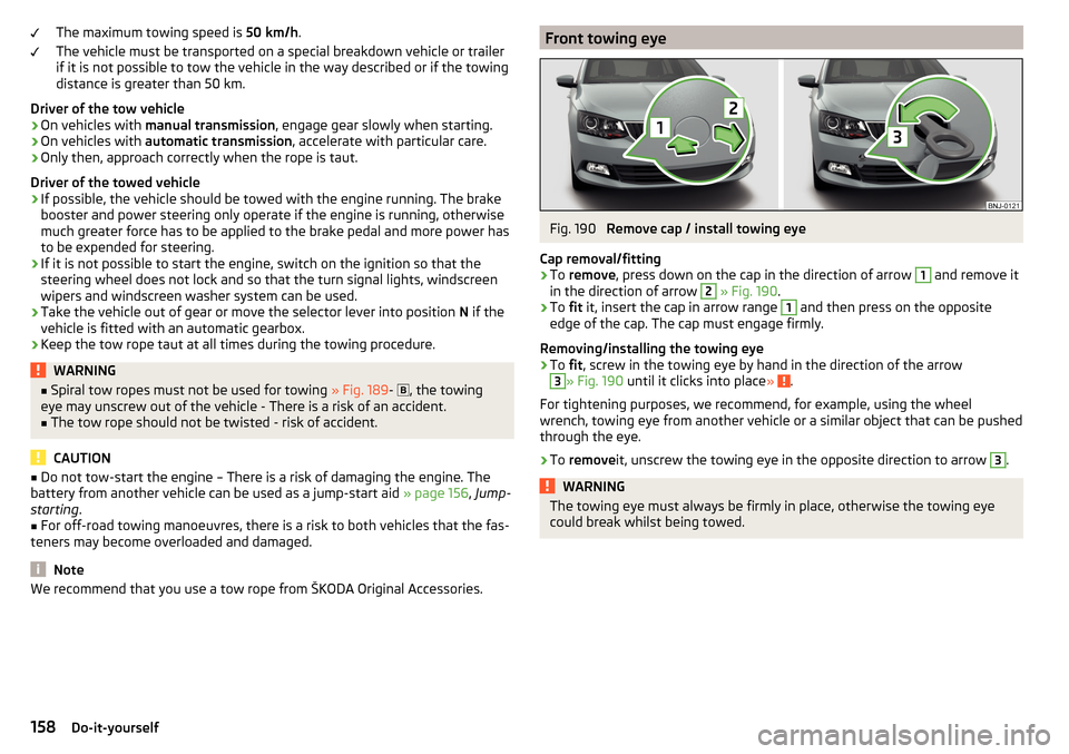
Remove cap / install towing eye
Cap removal/fitting
›
To remove , press down on the cap in the direction of arrow
1
and remove it
in the direction of arrow
2
» Fig. 190 .
›
To fit it, insert the cap in arrow range
1
and then press on the opposite
edge of the cap. The cap must engage firmly.
Removing/installing the towing eye
›
To fit, screw in the towing eye by hand in the direction of the arrow
3
» Fig. 190 until it clicks into place » .
For tightening purposes, we recommend, for example, using the wheel
wrench, towing eye from another vehicle or a similar object that can be pushed through the eye.
›
To remove it, unscrew the towing eye in the opposite direction to arrow
3
.
WARNINGThe towing eye must always be firmly in place, otherwise the towing eye
could break whilst being towed.158Do-it-yourself
Page 161 of 196
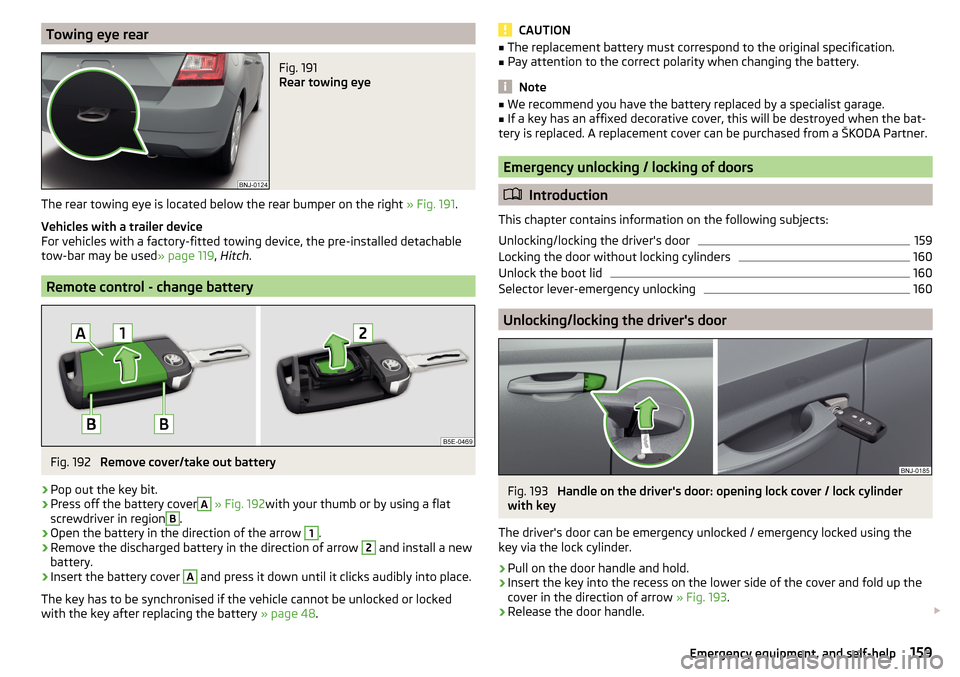
Towing eye rearFig. 191
Rear towing eye
The rear towing eye is located below the rear bumper on the right » Fig. 191.
Vehicles with a trailer device
For vehicles with a factory-fitted towing device, the pre-installed detachable
tow-bar may be used » page 119, Hitch .
Remote control - change battery
Fig. 192
Remove cover/take out battery
›
Pop out the key bit.
›
Press off the battery cover
A
» Fig. 192 with your thumb or by using a flat
screwdriver in region
B
.
›
Open the battery in the direction of the arrow
1
.
›
Remove the discharged battery in the direction of arrow
2
and install a new
battery.
›
Insert the battery cover
A
and press it down until it clicks audibly into place.
The key has to be synchronised if the vehicle cannot be unlocked or locked
with the key after replacing the battery » page 48.
CAUTION■
The replacement battery must correspond to the original specification.■Pay attention to the correct polarity when changing the battery.
Note
■We recommend you have the battery replaced by a specialist garage.■If a key has an affixed decorative cover, this will be destroyed when the bat-
tery is replaced. A replacement cover can be purchased from a ŠKODA Partner.
Emergency unlocking / locking of doors
Introduction
This chapter contains information on the following subjects:
Unlocking/locking the driver's door
159
Locking the door without locking cylinders
160
Unlock the boot lid
160
Selector lever-emergency unlocking
160
Unlocking/locking the driver's door
Fig. 193
Handle on the driver's door: opening lock cover / lock cylinder
with key
The driver's door can be emergency unlocked / emergency locked using the key via the lock cylinder.
›
Pull on the door handle and hold.
›
Insert the key into the recess on the lower side of the cover and fold up the
cover in the direction of arrow » Fig. 193.
›
Release the door handle.
159Emergency equipment, and self-help
Page 166 of 196
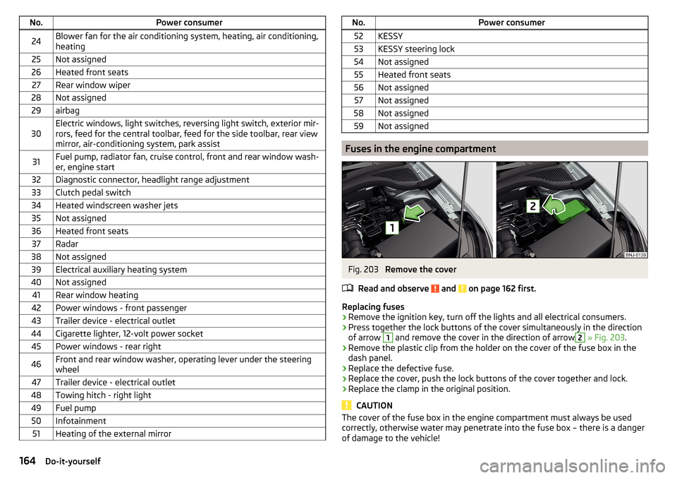
No.Power consumer24Blower fan for the air conditioning system, heating, air conditioning,
heating25Not assigned26Heated front seats27Rear window wiper28Not assigned29airbag30Electric windows, light switches, reversing light switch, exterior mir-
rors, feed for the central toolbar, feed for the side toolbar, rear view
mirror, air-conditioning system, park assist31Fuel pump, radiator fan, cruise control, front and rear window wash-
er, engine start32Diagnostic connector, headlight range adjustment33Clutch pedal switch34Heated windscreen washer jets35Not assigned36Heated front seats37Radar38Not assigned39Electrical auxiliary heating system40Not assigned41Rear window heating42Power windows - front passenger43Trailer device - electrical outlet44Cigarette lighter, 12-volt power socket45Power windows - rear right46Front and rear window washer, operating lever under the steering
wheel47Trailer device - electrical outlet48Towing hitch - right light49Fuel pump50Infotainment51Heating of the external mirrorNo.Power consumer52KESSY53KESSY steering lock54Not assigned55Heated front seats56Not assigned57Not assigned58Not assigned59Not assigned
Fuses in the engine compartment
Fig. 203
Remove the cover
Read and observe
and on page 162 first.
Replacing fuses
›
Remove the ignition key, turn off the lights and all electrical consumers.
›
Press together the lock buttons of the cover simultaneously in the direction
of arrow
1
and remove the cover in the direction of arrow
2
» Fig. 203 .
›
Remove the plastic clip from the holder on the cover of the fuse box in the
dash panel.
›
Replace the defective fuse.
›
Replace the cover, push the lock buttons of the cover together and lock.
›
Replace the clamp in the original position.
CAUTION
The cover of the fuse box in the engine compartment must always be used
correctly, otherwise water may penetrate into the fuse box – there is a danger
of damage to the vehicle!164Do-it-yourself
Page 175 of 196

Technical data
Technical data
Basic vehicle data
Introduction
This chapter contains information on the following subjects:
Vehicle data
173
Operating weight
174
Payload
175
measurement of fuel consumption and CO 2 emissions according to ECE
Regulations and EU Directives
175
Dimensions
176
Departure angle
177
The details given in the vehicle's technical documentation always take prece-
dence over the details in the Owner's Manual.
The performance values listed were determined without performance-reduc- ing equipment, e.g. air conditioning system.
The specified values have been determined in accordance with rules and under
conditions set out by legal or technical requirements for determining opera-
tional and technical data for motor vehicles.
The listed values are for the basic model without optional equipment.
Vehicle dataFig. 220
Vehicle data sticker/type plate
Vehicle data sticker
The vehicle data sticker » Fig. 220 -
is located on the base of the luggage
compartment and is also stuck into the Owner's Manual.
The vehicle data sticker contains the following data. Vehicle identification number (VIN)
Vehicle type
Gearbox code / paint number / interior equipment / engine output / engine code
Partial vehicle description
Approved tyre diameter in inches 1)
The approved tyres and rim sizes for your vehicle are listed in the vehicle's
technical documentation (the so called COC document) and this also states the
declaration of conformity.
Type plate
The type plate » Fig. 220 -
is located at the bottom of the B-pillar on the
right-hand driver's side.
The type plate contains the following data. Vehicle manufacturers
Vehicle identification number (VIN)
Maximum permissible gross weight
Maximum permissible towed weight (towing vehicle and trailer)
1234567891)
Only valid for some countries.
173Technical data
Page 176 of 196

Maximum permissible front axle load
Maximum permissible rear axle load
Vehicle identification number (VIN)
The vehicle identification number - VIN (vehicle body number) is stamped on
the right hand suspension strut dome in the engine compartment. This num-
ber is also located on a sign on the lower left hand edge below the windscreen
(together with a VIN bar code), together with a nameplate.
The VIN number can also be displayed in Infotainment » Owner´s Manual Info-
tainment .
Engine number
The engine number (three-digit code letter and serial number) is stamped onto
the engine block.
Supplementary Information (applies to Russia)
The full type approval number of the means of transport is indicated in the
registration documents, field 17.
Maximum permissible trailer weight
The listed maximum permissible trailer weight is only valid for altitudes up to
1000 m above sea level.
The engine output falls as altitude increases, as does the ability to climb.
Therefore, for every additional 1,000 m in height (or part), the maximum per-
missible towed weight must be reduced by 10 %.
The towed weight comprises the actual weights of the (loaded) towing vehicle and the (loaded) trailer.WARNINGDo not exceed the specified maximum permissible weights – risk of an acci-
dent and damage.
Operating weight
This value is only a guide value and corresponds to the lowest possible operat-
ing weight without any equipment added that would also increase the weight
(e.g. air conditioning, emergency or spare wheel etc.). It also includes a weight
allowance for the driver (75 kg), the weight of the operating fluids, the tool kit
and a fuel tank filled to 90 % capacity.
1011Operating weight - FabiaEngineGearboxOperating weight (kg)1.0 l/44 kW MPIMG10551.0 l/55 kW MPIMG (EU6)1055MG (EU4)10501.2 l./66 kW TSIMG11091.2 ltr./81 kW TSIMG1129DSG11541.6 l./66 kW MPIMG10861.6 l./81 kW MPIAG11261.4 l/55 kW TDI CRMG11561.4 l/66 kW TDI CRMG1156DSG11861.4 l/77 kW TDI CRMG1165
Operating weight - Fabia Combi
EngineGearboxOperating weight (kg)1.0 l/55 kW MPIMG (EU6)1079MG (EU4)10741.2 ltr./66 kW TSIMG11331.2 ltr./81 kW TSIMG1153DSG11781.6 l./66 kW MPIMG11101.6 l./81 kW MPIAG11501.4 l/55 kW TDI CRMG11801.4 l/66 kW TDI CRMG1180DSG12101.4 l/77 kW TDI CRMG1189
Note
If required, you can find out the precise weight of your vehicle by contacting a
specialist garage.174Technical data
Page 177 of 196

Payload
It is possible to calculate the approximate loading capacity from the difference
between the permissible total weight and the operating weight.
The payload consists of the following weights.
▶ The weight of the passengers.
▶ The weight of all items of luggage and other loads.
▶ The weight of the roof, including the roof rack system.
▶ The weight of the equipment that is excluded from the operating weight.
▶ Trailer drawbar load when towing a trailer (max. 50 kg).
measurement of fuel consumption and CO
2 emissions according to
ECE Regulations and EU Directives
The data on fuel consumption and CO 2 emissions were not available at the
time of going to press.
The data on fuel consumption and CO 2 emissions are given on the ŠKODA
websites or in the sales and technical vehicle documentation.
The measurement of the intra-urban cycle begins with a cold start of the en-
gine. Urban driving is then simulated.
In the extra-urban driving cycle, the vehicle is accelerated and decelerated in
all gears, corresponding to daily routine driving conditions. The driving speed
varies between 0 and 120 km/h.
The calculation of the combined fuel consumption considers a weighting of
about 37 % for the intra-urban cycle and 63 % for the extra-urban cycle.
Note
■ The emission and fuel consumption figures given on the ŠKODA websites or
in the commercial and technical vehicle documentation have been established
in accordance with rules and under conditions that are set out by statutory or
technical rules for the determination of operational and technical data of mo-
tor vehicles.■
Depending on the extent of the equipment, the driving style, traffic condi-
tions, weather influences and vehicle condition, consumption values can in
practice result in fuel economy figures in the use of the vehicle that differ from
the fuel consumption values listed on the ŠKODA websites or in the commer-
cial and technical vehicle documentation.
175Technical data
Page 184 of 196

Index
A
ABS Operation
101
Warning light31
ACC
110
Acceptance and recycling of used vehicles129
Accessories127
Adaptive cruise control automatic stop-start
111
Operation110
Set/change the desired speed112
special driving conditions113
Start control112
Stop/resume control112
Warning light30, 36
Adaptive Cruise Control110
Malfunctions114
Operation overview111
Overtaking114
Radar sensor100
Set the clearance level113
Trailer towing114
Adjusting Steering wheel
11
Adjusting the seats
10
Advance warning / Emergency braking36
Advice on tyre/wheel usage145
Air-conditioning system Air outlet vents
88
air bag16
airbag warning light
31
Airbag Adjustments and impairments to the airbag system
128
Deactivation18
Deployment17
Airbag system16
Air conditioning85
Climatronic87
Manual air conditioning86
Recirculated air mode88
Air outlet vents88
Alarm49
Trailer126
All-year tyres148
Anti-lock braking system (ABS)101
Anti-theft alarm system49
Trailer126
Anti-theft wheel bolts 153
Armrest Front
63
Ashtray69
Assembling the bar ball, Step 1
120
bar ball, Step 2121
Assist systems100
Auto Check Control37
Automatic drive Selector lever
96
Automatic driving light control55
automatic gearbox Tiptronic
97
Automatic gearbox Kickdown
98
Malfunction33
Selector lever-emergency unlocking160
Selector lever lock97
Starting-off and driving98
Warning light33
Automatic shutdown of consumers142
Automatic transmission96
Selector lever lock97
AUX67
Avoiding damage to your vehicle99
B
ball bar ready position
120
Ball head Check fitting
121
Ready position120
Battery Change in key
159
Belts13
Belt tensioners15
bike carriers82
Bluetooth See Owner´s Manual -Infotainment
6
Bonnet Closing
138
Opening138
Boot Cargo element
80
Class N1 vehicles80
Hooks77
see boot lid50
Boot lid Automatic locking
50
Open/Close50
Brake Assist (HBA)102
Brake booster93
Brake fluid142
Check142
specification142
Brake pads new
93
Brake pedal (automatic gearbox) Warning light
33
Brakes Brake booster
93
Brake fluid142
Braking and stabilisation systems101
Handbrake94
182Index
Page 186 of 196
DeactivationAirbag18
Delayed locking of the boot lid See boot lid
50
Departure angle177
Diesel136
Diesel fuel136
Diesel particle filter (DPF)35
Digital Clock37
Digital Service Plan131
Dipped beam53
Dipstick140
display cardinal points
36
Display Coolant temperature
28
Fuel level28
Gear changes37
In the instrument cluster36
MAXI DOT40
Service intervals41
Disposal Acceptance and recycling of used vehicles
129
Distance warning115
Warning light36
Door Child safety lock
48
Emergency locking160
Emergency locking of the driver's door159
Opening/Closing47
door alarm36
Drive Driving through water
99
DriveGreen98
driving emissions
175
fuel consumption175
Driving Maximum speed178
through water99
E
Economical driving
98
EDL102
Electric power windows Malfunctions
52
Electric windows50
Electric Windows Button in driver’s door’
51
Electronic differential lock (EDL, XDS)102
Electronic immobilizer90
Emergency Hazard warning light system
56
Jump-starting156, 157
Selector lever-unlocking160
Starting / stopping the engine with the push of a button
91
Starting the engine / stopping with the push of a button
92
Towing the vehicle157
Towing the vehicle using the trailer device159
Tyre repair154
Unlocking/locking the door159
Unlocking / locking the door160
Emergency equipment Fire extinguisher
150
First aid kit149
Jack150
Reflective vest149
Vehicle tool kit150
Warning triangle149
Emergency spare Removing / stowing
152
Emission control system31
Emissions175
Engine Information messages34
Running in98
Engine compartment137
Brake fluid142
Coolant140
Engine oil139
Overview138
Vehicle battery142
Windscreen washer fluid139
Engine drag torque control (MSR)101
Engine number173
engine oil specification
139
Engine oil139
Check140
Oil changing139
Refilling140
Warning light34
EPC31
ESC Operation
101
Warning light30
Extended warranty5
F
Fastening elements
76
Fatigue detection116
Films132
Fire extinguisher150
First aid kit149
Flashing54
Flexible storage compartment80
Fog lights Warning light
33
Fog lights/rear fog light55
Fog lights with the CORNER function56
Footmats95
see Footmats95
184Index