mirror SKODA FABIA 2016 3.G / NJ Owner's Manual
[x] Cancel search | Manufacturer: SKODA, Model Year: 2016, Model line: FABIA, Model: SKODA FABIA 2016 3.G / NJPages: 196, PDF Size: 31.86 MB
Page 4 of 196
Table of Contents
Materials defect liability and ŠKODA warranty
for new cars4
On-board literature
6
Notes
7
Structure of the Owner's Manual and further
information
8
Abbreviations
Safety
Passive Safety
10
General information
10
Correct and safe seated position
10
Seat belts
13
Wearing seat belts
13
Inertia reel and belt pre-tensioners
15
Airbag system
16
Description of the airbag system
16
Airbag deactivation
18
Transporting children safely
20
Child seat
20
Fastening systems
23
Operation
cockpit
26
Overview
25
Instruments and warning lights
27
Instrument cluster
27
Warning lights
28
Information system
36
Driver information system
36
Operation of the information system
38Driving data (Multifunction display)38MAXI DOT display40
Service interval display
41
SmartGate
42
Unlocking and opening
44
Unlocking and locking
44
Anti-theft alarm system
49
Tailgate
50
window operation
50
Lights and visibility
53
Lights
53
Interior lighting
57
Visibility
58
Windscreen wipers and washers
59
Rear view mirror
61
Seats and headrests
62
Front seats
62
Rear seats
63
Headrests
64
Front seat heater
65
Useful features
66
Interior fittings
66
Tablet holder
73
Transport of cargo
75
Luggage compartment and transporting
objects
75
Variable loading floor in the luggage
compartment
81
Bicycle carrier in the luggage compartment
82
Transportation on the roof rack
84
Heating and ventilation
85
Heating, manual air conditioning system,
Climatronic
85Driving
Starting-off and driving90
Starting and stopping the engine
90
START-STOPsystem
92
Brakes and Parking
93
Manual gear shifting and pedals
95
Automatic transmission
96
Running in and economical driving
98
Avoiding damage to your vehicle
99
Assist systems
100
General information
100
Braking and stabilisation systems
101
Parking aid (ParkPilot)
103
Reversing camera
105
Cruise Control System
107
Speed limiter
108
Adaptive Cruise Control (ACC)
110
Front Assist
114
Fatigue detection
116
Tyre pressure monitoring
117
Towing device and trailer
119
Hitch
119
Using hitch
123
General Maintenance
Care and maintenance
127
Service work, adjustments and technical
alterations
127
Service intervals
129
Cleaning and care
131
Inspecting and replenishing
135
Fuel
135
Engine compartment
137
Engine oil
139
Coolant
1402Table of Contents
Page 12 of 196
Safety
Passive Safety
General information
Introduction
This chapter contains information on the following subjects:
Before every journey
10
Driving safety
10
In this section of the instructions you will find important information on the
subject of passive safety. We have combined everything here which you
should be familiar with, for example, regarding seat belts, airbags, safety of children and anything similar.
Other important safety information can also be found in the subsequent sec-
tions of this Owner's Manual. Therefore, the Owner’s Manual should always be
kept in the vehicle.
Before every journey
For your own safety and the safety of the people travelling with you, please
pay attention to the following points before setting off.
▶ Check the lights and turn signal lights are functioning correctly.
▶ Check the wiper function and the wiper blades for wear. Check the wind-
screen washer fluid level.
▶ Ensure that all of the windows offer good visibility to the outside.
▶ Adjust the rear-view mirror so that vision to the rear is guaranteed. Ensure
that the mirrors are not covered.
▶ Check the tyre inflation pressure.
▶ Check the engine oil, brake fluid and coolant levels.
▶ Secure all items of luggage.
▶ Do not exceed the permissible axle loads and permissible gross weight of the
vehicle – risk of accident.
▶ Close all doors and the engine compartment and luggage compartment lid.
▶ Ensure that no objects can obstruct the pedals.
▶
Protect children using a suitable child seat » page 20, Transporting children
safely .
▶ Adopt the correct seated position. Tell your passengers to assume the cor-
rect seated position » page 10, Correct and safe seated position .
Driving safety
For safety in traffic, the following precautions must be observed. ▶ Do not become distracted from concentrating on the traffic situation, (e.g. by
your passengers or mobile phone calls).
▶ Never drive when your driving ability is impaired, (e.g. due to medication, al-
cohol, drugs or similar).
▶ Keep to the traffic regulations and the permissible speed limit.
▶ Always adjust the driving speed to the road, traffic and weather conditions.
▶ Take regular breaks on long journeys (at least every two hours).
Correct and safe seated position
Introduction
This chapter contains information on the following subjects:
The correct seating position for the driver
11
Adjusting the steering wheel position
11
Correct seating position for the front passenger
12
Correct seating position for the passengers in the rear seats
12
Always assume the correct seated position before setting off and do not
change this position while driving. Also advise your passengers to adopt the
correct seated position and not to change this position while the car is moving.
The following list contains instructions for the Passenger which, if not ob-
served, may cause serious injuries or death. ▶ Do not lean against the dash panel.
▶ Do not put your feet on the dash panel.
The following list contains instructions for all Passengers which, if not ob-
served, may cause serious injuries or death.
▶ Do not sit only on the front edge of the seat.
▶ Do not sit facing to one side.
▶ Do not lean out of the window.
▶ Do not put your limbs out of the window.
▶ Do not put your feet on the seat upholstery.
10Safety
Page 28 of 196
Operation
cockpit
OverviewElectric windows
51
Door opening lever
47
Electric exterior mirror adjustment
61
Air outlet vents
88
Ticket holder
66
Operating lever (depending on equipment):
▶ Direction and high beam
54
▶Speed regulating system
107
▶Speed limiter
108
Steering wheel with horn / with driver's front airbag
16
Buttons for operating the information system
36
Instrument cluster
27
Operating lever:
▶ Windscreen wipers and washers
59
▶Information system
36
Depending on equipment fitted:
▶ Storage compartment
68
▶Infotainment » User Owner's Manual for Infotainment
Bar with keys depending on the equipment fitted:
▶ Left seat heating
65
▶
Rear window heating
58
▶
Central locking system
46
▶
Hazard lights
56
▶
Warning light for the front passenger airbag
19
▶
Right seat heating
65
Interior rear-view mirror
61
Memory card slot (in the front passenger storage compartment)
» Infotainment Owner's Manual
Front passenger airbag
16
Storage compartment on the front passenger side
71
Key switch for switching off the front passenger airbag (in front
passenger storage compartment)
191234567891011121314151617Electric window in the front passenger door51
Storage compartment
67
Bar with keys depending on the equipment fitted:
▶ START STOP
92
▶
Traction control (TCS)
102
▶
Parking aid
103
▶
Tyre Press. Loss Indicator
117
Light switch
53
Bonnet release lever
138
Regulator for headlamp beam adjustment for the headlights
53
Operating lever for adaptive cruise control
111
Steering wheel locking lever
11
Depending on equipment fitted:
▶ Ignition lock
91
▶Starter button
91
Cup holder
68
Coin and card holders
67
Handbrake lever
94
Depending on equipment fitted:
▶ Gearshift lever (manual gearbox)
95
▶Selector lever (automatic gearbox)
96
Storage compartment
67
USB input / AUX input
67
Depending on equipment fitted:
▶ 12-Volt power socket
70
▶Cigarette lighter
69
Controls for heating / air conditioning
85
Note
The layout of the controls on right-hand drive vehicles differs partially from
that shown in this layout » Fig. 16.181920212223242526272829303132333426Operation
Page 57 of 196
WARNINGOnly turn on the main beam or the headlight flasher if other road users will
not be dazzled.
Automatic driving light control
Fig. 42
Light switch: AUTO position
Read and observe on page 53 first.
The light switch is in position
» Fig. 42 then depending on the equipment
the automatic switch on / off the lights corresponding to the light or weather
conditions (rain) takes place.
If the light switch is in position
, the lettering
illuminates next to the
light switch. If the light is switched on automatically, the symbol
also illumi-
nates next to the light switch.
Automatic driving light control in the rain (hereafter referred to as function)
The dipped beam is switched on automatically if the following conditions are
met.
The parking aid is activated.
The light switch is in the position
.
The windscreen wipers are on for more than 15 s.
The light turns off automatically about 4 minutes after turning off the wipers.
Setting, activation/deactivation
The following functions can be set or activated/deactivated in Infotainment
» Owner's Manual .
▶ Sensitivity adjustment of the sensor for determining the lighting conditions
for automatic driving light control
▶ Automatic driving-light control during rain
CAUTIONPoorer visibility is detected by a sensor mounted below the windscreen in the
holder of the inside mirror or in the control panel. Do not cover the sensor - the
system can be affected.
Fog lights/rear fog light
Fig. 43
Light switch - Switch front/rear
fog light
Read and observe on page 53 first.
Switching on the fog lights / rear fog lights is possible if the following condi-
tions apply.
The lights switch is in position
,
or
» Fig. 43 .
›
Toswitch on thefog lights ,turn the light switch to position
1
; the warning
light
illuminates in the instrument cluster.
›
To turn on therear fog light , pull the light switch to position
2
, the indicator
light
will light up in the instrument cluster.
If the vehicle is not fitted with fog lights,therear fog light is switched on by
pulling out the light switch to the only possible setting.
The fog lights/rear fog light are switched offin the reverse order.
Note
While driving with an accessory connected to the trailer socket (e.g. trailer,
bike carrier) only the equipment is illuminated by the fog light. The towing de-
vice must be installed at the factory or from the ŠKODA original accessories.55Lights and visibility
Page 58 of 196
Fog lights with the CORNER functionRead and observe
on page 53 first.
The CORNER function automatically switches on the fog lights on the respec-tive side of the vehicle (e.g. when cornering), if the following conditions are
met.
The turn signal is switched on or the front wheels are turned sharply 1)
.
The vehicle speed is below 40 km/h.
The low beam is switched on.
The fog lights are not switched on.
The two fog lights are switched on when you shift into the reverse gear.
COMING HOME / LEAVING HOME
Read and observe
on page 53 first.
The function COMING HOME ensures that the vehicle's environment is illumi-
nated after switching off the ignition and opening the driver's door.
The function LEAVING HOME ensures that the vehicle's environment is illumi-
nated after unlocking the vehicle with the radio remote control unit.
The function switches the light on only if there is poorer visibility and the light
switch is in the position .
The two functions can be activated/deactivated and set in Infotainment
» Owner's Manual Infotainment .
CAUTION
■
Poorer visibility is detected by a sensor mounted below the windscreen in
the holder of the inside mirror or in the control panel. Do not cover the sensor -
the system can be affected.■
If this option is always enabled, then the battery is heavily loaded.
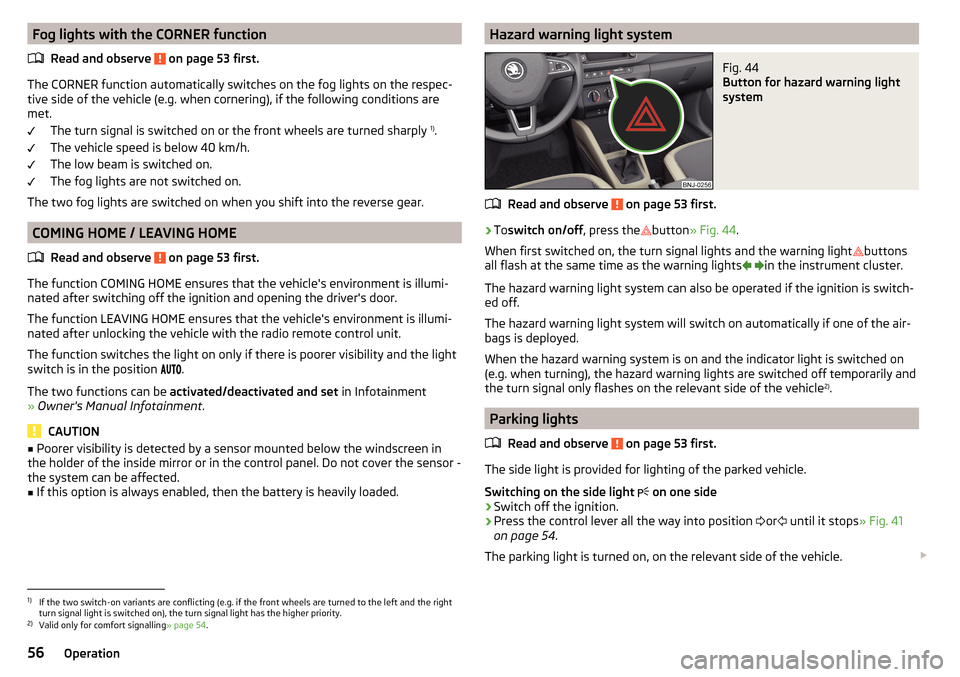
Hazard warning light systemFig. 44
Button for hazard warning light
system
Read and observe on page 53 first.
›
To switch on/off , press the
button
» Fig. 44 .
When first switched on, the turn signal lights and the warning light buttons
all flash at the same time as the warning lights
in the instrument cluster.
The hazard warning light system can also be operated if the ignition is switch-
ed off.
The hazard warning light system will switch on automatically if one of the air-
bags is deployed.
When the hazard warning system is on and the indicator light is switched on
(e.g. when turning), the hazard warning lights are switched off temporarily and
the turn signal only flashes on the relevant side of the vehicle 2)
.
Parking lights
Read and observe
on page 53 first.
The side light is provided for lighting of the parked vehicle.
Switching on the side light on one side
›
Switch off the ignition.
›
Press the control lever all the way into position
or
until it stops
» Fig. 41
on page 54 .
The parking light is turned on, on the relevant side of the vehicle.
1)
If the two switch-on variants are conflicting (e.g. if the front wheels are turned to the left and the right
turn signal light is switched on), the turn signal light has the higher priority.
2)
Valid only for comfort signalling » page 54.
56Operation
Page 61 of 196
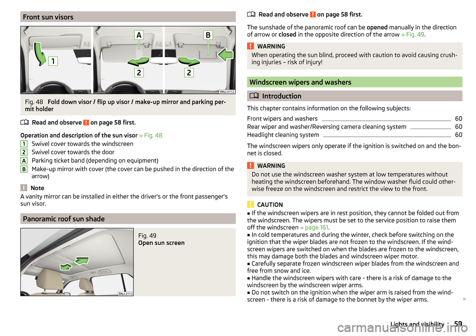
Front sun visorsFig. 48
Fold down visor / flip up visor / make-up mirror and parking per-
mit holder
Read and observe
on page 58 first.
Operation and description of the sun visor » Fig. 48
Swivel cover towards the windscreen
Swivel cover towards the door
Parking ticket band (depending on equipment)
Make-up mirror with cover (the cover can be pushed in the direction of the
arrow)
Note
A vanity mirror can be installed in either the driver's or the front passenger's
sun visor.
Panoramic roof sun shade
Fig. 49
Open sun screen
12ABRead and observe on page 58 first.
The sunshade of the panoramic roof can be opened manually in the direction
of arrow or closed in the opposite direction of the arrow » Fig. 49.
WARNINGWhen operating the sun blind, proceed with caution to avoid causing crush-
ing injuries – risk of injury!
Windscreen wipers and washers
Introduction
This chapter contains information on the following subjects:
Front wipers and washers
60
Rear wiper and washer/Reversing camera cleaning system
60
Headlight cleaning system
60
The windscreen wipers only operate if the ignition is switched on and the bon-
net is closed.
WARNINGDo not use the windscreen washer system at low temperatures without
heating the windscreen beforehand. The window washer fluid could other-
wise freeze on the windscreen and restrict the view to the front.
CAUTION
■ If the windscreen wipers are in rest position, they cannot be folded out from
the windscreen. The wipers must be set to the service position to raise them
off the windscreen » page 161.■
In cold temperatures and during the winter, check before switching on the
ignition that the wiper blades are not frozen to the windscreen. If the wind-
screen wipers are switched on when the blades are frozen to the windscreen,
this may damage both the blades and windscreen wiper motor.
■
Carefully separate frozen windscreen wiper blades from the windscreen and
free from snow and ice.
■
Handle the windscreen wipers with care - there is a risk of damage to the
windscreen by the windscreen wiper arms.
■
Do not switch on the ignition when the wiper arm is raised from the wind-
screen - there is a risk of damage to the bonnet by the wiper arms.
59Lights and visibility
Page 63 of 196
Rear view mirror
Introduction
This chapter contains information on the following subjects:
Interior mirror dimming
61
Mirrors
61WARNINGExterior mirrors increase the field of view, however, they make objects ap-
pear smaller and further away. Therefore, use the interior mirror whenever
possible for assessing the distances to the vehicles following behind.
Interior mirror dimming
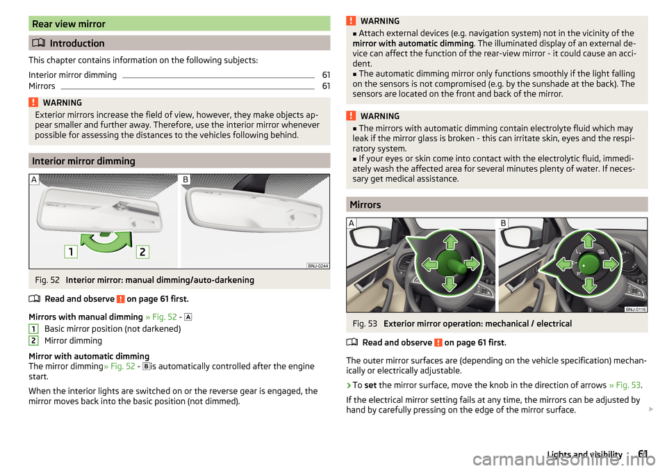
Fig. 52
Interior mirror: manual dimming/auto-darkening
Read and observe
on page 61 first.
Mirrors with manual dimming » Fig. 52 -
Basic mirror position (not darkened)
Mirror dimming
Mirror with automatic dimming
The mirror dimming » Fig. 52 -
is automatically controlled after the engine
start.
When the interior lights are switched on or the reverse gear is engaged, the
mirror moves back into the basic position (not dimmed).
12WARNING■ Attach external devices (e.g. navigation system) not in the vicinity of the
mirror with automatic dimming . The illuminated display of an external de-
vice can affect the function of the rear-view mirror - it could cause an acci-
dent.■
The automatic dimming mirror only functions smoothly if the light falling
on the sensors is not compromised (e.g. by the sunshade at the back). The
sensors are located on the front and back of the mirror.
WARNING■ The mirrors with automatic dimming contain electrolyte fluid which may
leak if the mirror glass is broken - this can irritate skin, eyes and the respi-
ratory system.■
If your eyes or skin come into contact with the electrolytic fluid, immedi-
ately wash the affected area for several minutes plenty of water. If neces-
sary get medical assistance.
Mirrors
Fig. 53
Exterior mirror operation: mechanical / electrical
Read and observe
on page 61 first.
The outer mirror surfaces are (depending on the vehicle specification) mechan-
ically or electrically adjustable.
›
To set the mirror surface, move the knob in the direction of arrows » Fig. 53.
If the electrical mirror setting fails at any time, the mirrors can be adjusted by
hand by carefully pressing on the edge of the mirror surface.
61Lights and visibility
Page 64 of 196
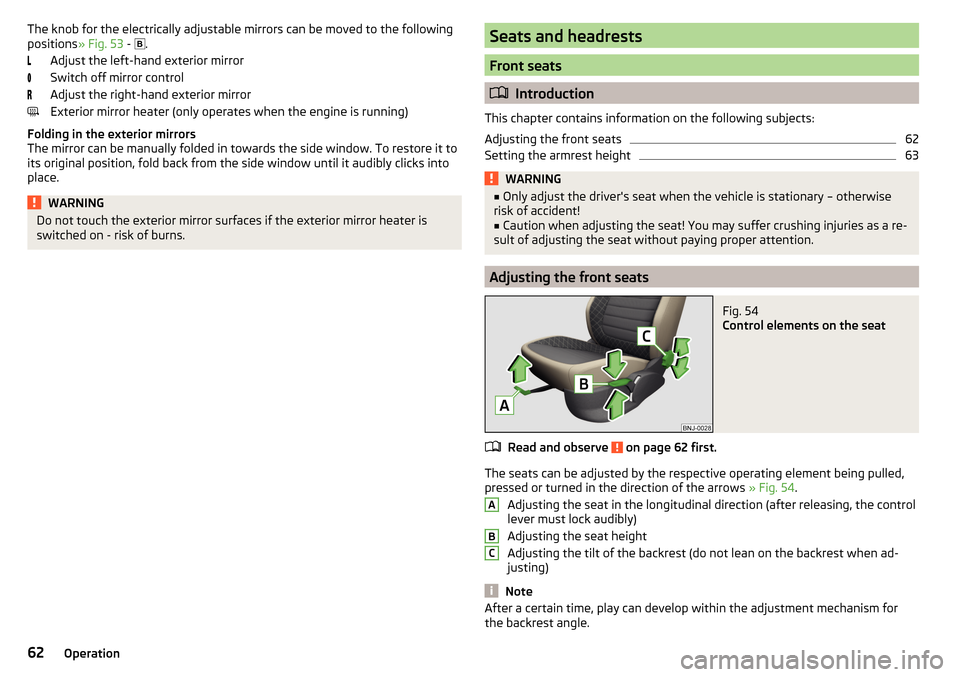
The knob for the electrically adjustable mirrors can be moved to the following
positions » Fig. 53 - .
Adjust the left-hand exterior mirror
Switch off mirror control
Adjust the right-hand exterior mirror
Exterior mirror heater (only operates when the engine is running)
Folding in the exterior mirrors
The mirror can be manually folded in towards the side window. To restore it to
its original position, fold back from the side window until it audibly clicks into
place.WARNINGDo not touch the exterior mirror surfaces if the exterior mirror heater is
switched on - risk of burns.Seats and headrests
Front seats
Introduction
This chapter contains information on the following subjects:
Adjusting the front seats
62
Setting the armrest height
63WARNING■ Only adjust the driver's seat when the vehicle is stationary – otherwise
risk of accident!■
Caution when adjusting the seat! You may suffer crushing injuries as a re-
sult of adjusting the seat without paying proper attention.
Adjusting the front seats
Fig. 54
Control elements on the seat
Read and observe on page 62 first.
The seats can be adjusted by the respective operating element being pulled,
pressed or turned in the direction of the arrows » Fig. 54.
Adjusting the seat in the longitudinal direction (after releasing, the control
lever must lock audibly)
Adjusting the seat height
Adjusting the tilt of the backrest (do not lean on the backrest when ad-
justing)
Note
After a certain time, play can develop within the adjustment mechanism for
the backrest angle.ABC62Operation
Page 109 of 196
Distance of the orientation lines behind the vehicle » Fig. 133
The distance is about 40 cm (safety distance limit).
The distance is about 100 cm.
The distance is about 200 cm.
The distance may vary slightly depending on the load of the vehicle and the
road inclination.
The distance between the side lines corresponds approximately to the vehicle
width including mirrors.
Functional surfaces » Fig. 133
Depending on the Infotainment Type: Turns the display of the area be-
hind the vehicle off
Display settings - brightness, contrast, colour Switching audible parking signals on/off
Enabling and reduced park assistance display
Change to park assistance display
CAUTION
The objects shown in the display can be closer or even further away than they
appear. This is especially the case in the following situations.■
Protruding objects, such as the rear of a truck and the like.
■
When driving from a horizontal surface into a slope or a depression.
■
When driving from a slope or a depression onto a horizontal surface.
Cruise Control System
Introduction
This chapter contains information on the following subjects:
Operation
107
Operation description
108
The Cruise Control System (CCS) maintains a set speed without you having to
actuate the accelerator pedal. The status where the CCS maintains the speed
is referred to hereinafter as the control.
ABC WARNING■
The general information relating to the use of assistance systems must
be observed » page 100, in section Introduction .■
After pressing the clutch pedal, no interrupted control occurs! For exam-
ple, if a different gear is engaged and the clutch pedal is released, control is
continued.
Operation
Fig. 134
Maxi DOT display: Examples of status displays the CCS
Fig. 135
Segment display: Examples of status displays the CCS
Read and observe
on page 107 first.
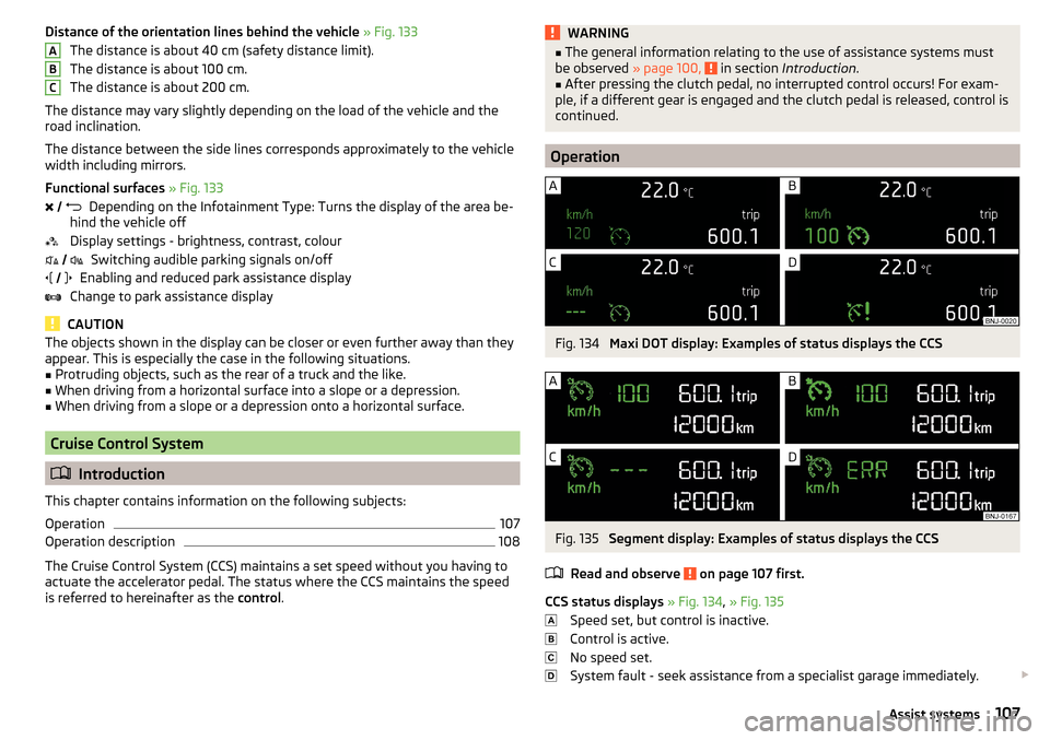
CCS status displays » Fig. 134 , » Fig. 135
Speed set, but control is inactive.
Control is active.
No speed set.
System fault - seek assistance from a specialist garage immediately.
107Assist systems
Page 125 of 196

CAUTION■Place the tow bar in the standby position, with the key upwards, and store in
the box - otherwise there is a risk of damage to the key!■
Do not use excessive force when handling the operating lever (e.g. do not
step on it).
Vertical load with mounted accessories
Fig. 161
Representation of the maximum
length of the mounted accesso-
ries and the permissible total
weight of the accessory depend-
ing on the load centre of gravity
Read and observe on page 119 first.
When using the accessories (e.g. bicycle carrier), the maximum length and the
permissible total weight including load must be considered.
The maximum length of the mounted accessories (from the ball of the towing
device) is 70 cm » Fig. 161 .
The total permitted weight of the accessories including load changes with in-
creasing distance of the load centre of gravity from the ball head of the towing
device.
Distance of the load centre of gravity from the ball headPermissible total weight of the ac-cessories, including load0 cm50 kg30 cm50 kg60 cm25 kg70 cm0 kg
CAUTION
Never exceed the permissible total weight of the accessories incl. load and
maximum length of the accessories - risk of damage to the towing device.NoteWe recommend that you use the accessories from ŠKODA Original Accessories.
Using hitch
Trailer (accessory) connect and disconnect
Fig. 162
Housing of the 13 pin socket,
safety eyelet
Connect and disconnect
›
Install the ball bar and the remove the protective cap
3
» Fig. 150 on page 119
lose weight.
›
Place the trailer (the accessory) onto the tow ball.
›
Plug the trailer cable into 13-pin socket
A
» Fig. 162 . (If the trailer / accesso-
ries have a 7-pin connector, use a corresponding reduction piece from the
ŠKODA Original Accessories).
›
Suspend the breakaway cable of the trailer at the safety eyelet
B
(the
breakaway cable must sag in all trailer settings in view of the vehicle).
Uncoupling takes place in reverse order.
Exterior mirrors
You should have additional exterior mirrors fitted if you are not able to see the
traffic behind the trailer using the standard rear-view mirrors.
Headlights
The front of the vehicle may lift up when a trailer (accessory) is being towed
and the headlights may dazzle other road users. Set the range of the head-
lights » page 53 , Operating the lights .
Power supply of the trailer / accessory power system
In the electrical connection between the vehicle and trailer (accessory), the
trailer (accessories) is supplied with power from the vehicle (with ignition
switched on and off).
123Towing device and trailer