sensor SKODA KODIAQ 2016 1.G Owner's Manual
[x] Cancel search | Manufacturer: SKODA, Model Year: 2016, Model line: KODIAQ, Model: SKODA KODIAQ 2016 1.GPages: 344, PDF Size: 58.96 MB
Page 23 of 344
WARNING (Continued)■The airbag system must be replaced if it has been deployed.■In the area of the front airbag and the knee airbag, the surface of the
steering wheel and the dashboard should be cleaned using only a dry cloth
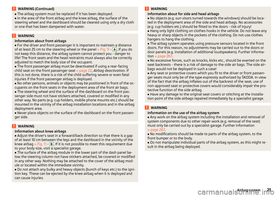
or one that has been dampened with water.WARNINGInformation about front airbags■For the driver and front passenger it is important to maintain a distance
of at least 25 cm to the steering wheel or the panel » Fig. 11 - A
, If you do
not keep this distance, the airbag system cannot protect you - danger to
life! The front seats and the head restraints must always also be correctly
adjusted to match the body size of the occupant.
■
The front passenger airbag must be deactivated if using a rear-facing
child seat on the front passenger seat » page 22, Airbag deactivation . If
this is not done, there is a risk of the child suffering severe or even fatal
injuries if the front passenger airbag is deployed.
■
No other persons, animals or objects may be positioned in front of the oc-
cupants on the front seats in the deployment area of the front air bags.
■
The steering wheel and the surface of the dashboard on the front pas-
senger side must not have stickers attached, covered or modified in any
other way. No parts (e.g. cup holders, mobile phone mounts etc.( should be
mounted in the vicinity of the airbag installation locations and in the airbag
deployment area.
■
Never place objects on the surface of the dashboard on the front passen-
ger side.
WARNINGInformation about knee airbags■Adjust the driver's seat in a forward/back direction so that there is a gap
of at least 10 cm between the legs and the dashboard in the vicinity of the
knee airbag » Fig. 11 - B
. If it is not possible to meet this requirement due
to your body size, visit a specialist garage.
■
The surface of the airbag module in the lower part of the dash panel be-
low the steering column not have stickers attached, be covered or modified
in any other way. Nothing may be attached to the cover of the airbag mod-
ule or located within the immediate vicinity.
■
Do not attach any bulky and heavy objects (bunch of keys etc.) to the igni-
tion key. These can be ejected by the knee airbag when it is deployed and
can cause injuries.
WARNINGInformation about for side and head airbags■No objects (e.g. sun visors turned towards the windows) should be loca-
ted in the deployment area of the side and head airbags. No accessories
(e.g. cup holders etc.) should be fitted to the doors - risk of injury!■
Hang only light clothing on clothes hooks in the vehicle. Do not leave any
heavy or sharp objects in the pockets of the clothing. Do not use clothes
hangers to hang the clothing.
■
The airbag system operates using pressure sensors located in the front
doors. For this reason, no adjustments may be carried out to the doors or
door panels (e.g. installation of additional loudspeakers). Further informa-
tion » page 267 .
■
No excessive forces, such as knocks, kicks etc., should be exerted on the
seat backrests - there is a risk of damage to the side air bags. The side air-
bags would not be deployed in such a case!
■
Any seat or protective covers which you fit to the driver or front passen-
ger seats must only be of the type expressly authorized by ŠKODA. In view
of the fact that the airbag inflates out of the backrest of the seat, use of
non-approved seat or protective covers would considerably impair the pro-
tective function of the side airbag.
■
Have any damage to the original seat covers or stitching at the installa-
tion point of the side airbags repaired immediately by a specialist garage.
WARNINGInformation on the use of the airbag system■Any work on the airbag system including the installation and removal of
system components due to other repair work (e.g. removal of the seat)
must only be carried out by a specialist garage. Further information
» page 267 .■
No modifications should be made to parts of the airbag system, to the
front bumper or to the body.
■
Do not manipulate individual parts of the airbag system, as this might re-
sult in the airbag being deployed.
21Airbag system
Page 42 of 344
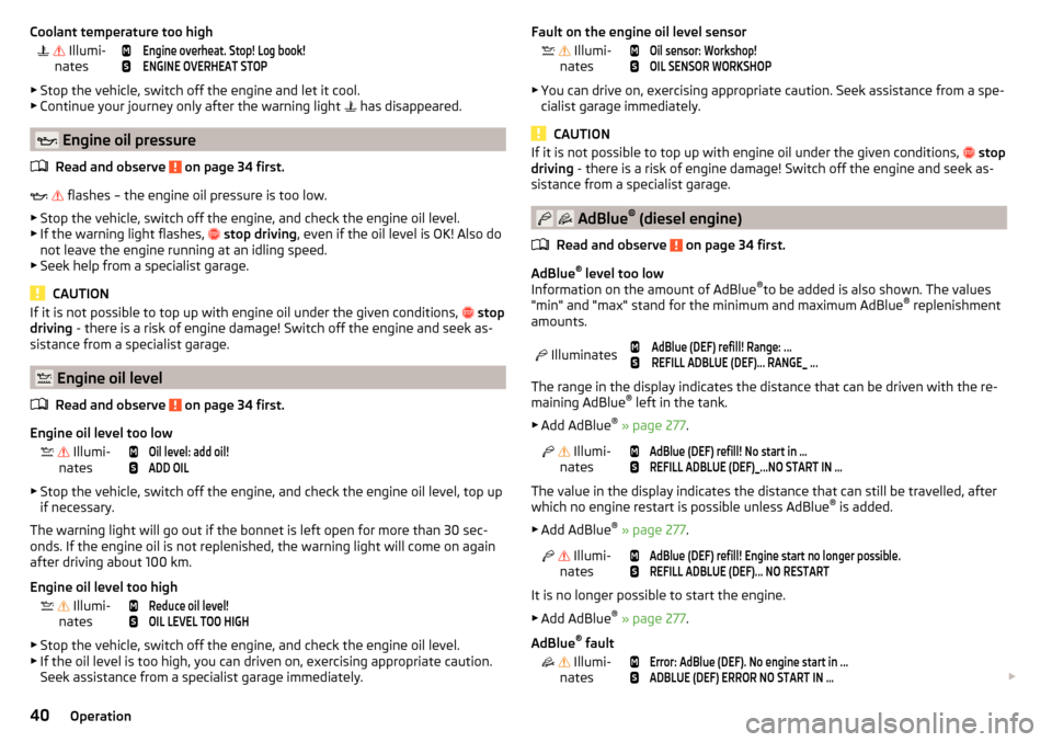
Coolant temperature too high Illumi-
nates
Engine overheat. Stop! Log book!ENGINE OVERHEAT STOP
▶ Stop the vehicle, switch off the engine and let it cool.
▶ Continue your journey only after the warning light
has disappeared.
Engine oil pressure
Read and observe
on page 34 first.
flashes – the engine oil pressure is too low.
▶ Stop the vehicle, switch off the engine, and check the engine oil level.
▶ If the warning light flashes,
stop driving , even if the oil level is OK! Also do
not leave the engine running at an idling speed.
▶ Seek help from a specialist garage.
CAUTION
If it is not possible to top up with engine oil under the given conditions, stop
driving - there is a risk of engine damage! Switch off the engine and seek as-
sistance from a specialist garage.
Engine oil level
Read and observe
on page 34 first.
Engine oil level too low
Illumi-
nates
Oil level: add oil!ADD OIL
▶ Stop the vehicle, switch off the engine, and check the engine oil level, top up
if necessary.
The warning light will go out if the bonnet is left open for more than 30 sec-
onds. If the engine oil is not replenished, the warning light will come on again
after driving about 100 km.
Engine oil level too high
Illumi-
nates
Reduce oil level!OIL LEVEL TOO HIGH
▶ Stop the vehicle, switch off the engine, and check the engine oil level.
▶ If the oil level is too high, you can driven on, exercising appropriate caution.
Seek assistance from a specialist garage immediately.
Fault on the engine oil level sensor Illumi-
nates
Oil sensor: Workshop!OIL SENSOR WORKSHOP
▶ You can drive on, exercising appropriate caution. Seek assistance from a spe-
cialist garage immediately.
CAUTION
If it is not possible to top up with engine oil under the given conditions, stop
driving - there is a risk of engine damage! Switch off the engine and seek as-
sistance from a specialist garage.
AdBlue ®
(diesel engine)
Read and observe
on page 34 first.
AdBlue ®
level too low
Information on the amount of AdBlue ®
to be added is also shown. The values
"min" and "max" stand for the minimum and maximum AdBlue ®
replenishment
amounts.
Illuminates
AdBlue (DEF) refill! Range: ...REFILL ADBLUE (DEF)... RANGE_ ...
The range in the display indicates the distance that can be driven with the re-
maining AdBlue ®
left in the tank.
▶ Add AdBlue ®
» page 277 .
Illumi-
nates
AdBlue (DEF) refill! No start in ...REFILL ADBLUE (DEF)_...NO START IN …
The value in the display indicates the distance that can still be travelled, after
which no engine restart is possible unless AdBlue ®
is added.
▶ Add AdBlue ®
» page 277 .
Illumi-
nates
AdBlue (DEF) refill! Engine start no longer possible.REFILL ADBLUE (DEF)... NO RESTART
It is no longer possible to start the engine.
▶ Add AdBlue ®
» page 277 .
AdBlue ®
fault
Illumi-
nates
Error: AdBlue (DEF). No engine start in ...ADBLUE (DEF) ERROR NO START IN …
40Operation
Page 55 of 344
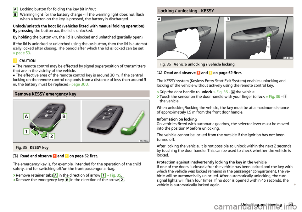
Locking button for folding the key bit in/out
Warning light for the battery charge - if the warning light does not flash
when a button on the key is pressed, the battery is discharged.
Unlock/unlatch the boot lid (vehicles fitted with manual folding operation)
By pressing the button
, the lid is unlocked.
By holding the button
, the lid is unlocked and unlatched (partially open).
If the lid is unlocked or unlatched using the
button, then the lid is automat-
ically locked after closing. The period after which the lid is locked can be set
» page 59 .
CAUTION
■
The remote control may be affected by signal superposition of transmitters
that are in the vicinity of the vehicle.■
The effective area of the remote control key is around 30 m. If the central
locking on the remote control responds from a distance of less than around 3
m, the battery must be replaced » page 300.
Remove KESSY emergency key
Fig. 35
KESSY key
Read and observe
and on page 52 first.
The emergency key is, for example, intended for the operation of the child
safety, and for switching off/on the front passenger airbag.
›
Remove retainer tabs
A
in the direction of arrow
1
» Fig. 35 .
›
Remove the emergency key
B
in the direction of the arrow
2
.
ABLocking / unlocking - KESSYFig. 36
Vehicle unlocking / vehicle locking
Read and observe
and on page 52 first.
The KESSY system (Keyless Entry Start Exit System) enables unlocking and
locking of the vehicle without actively using the remote control key.
›
Grip the door handle to unlock » Fig. 36 -
the vehicle.
›
Touch the sensor on the door handle with your finger to
lock » Fig. 36 -
the vehicle.
When unlocking/locking the vehicle, the key must be at a maximum distance
of approximately 1.5 m from the front door handle.
Information on locking
On vehicles fitted with automatic gearbox, the selector lever must be moved
into the position P before unlocking.
The vehicle cannot be locked from the outside if the ignition has not been
turned off.
After locking the vehicle, it is not possible to unlock within the next 2 seconds
by touching the door handle. This can be used to check whether the vehicle is
locked.
Protection against inadvertently locking the key in the vehicle
If one of the doors is closed after the vehicle has been locked and the key with
which the vehicle was locked remains in the passenger compartment, the ve-
hicle will be automatically unlocked. After automatically unlocking, the turn
signal lights will flash four times. If no door is opened within 45 seconds, the
vehicle is automatically locked again.
53Unlocking and opening
Page 63 of 344
MalfunctionsRead and observe
and on page 59 first.
Examples of operational malfunctions
Description of the malfunc-
tionRemedyThe lid cannot be openedUnlocking the lid » page 303
The lid does not react to an
opening signal
Removing a possible obstacle (e.g. snow), re-
opening the lid » page 60
Press handle A
» Fig. 45 on page 60 and pull
the lid upwards
The lid remains in the top
position
Manual closing of the lid
The lid is open and the bat-
tery was disconnected
Close manually
Close the door slowly, push down the lid, push in the lock on the centre of the
edge, above the ŠKODA logo.
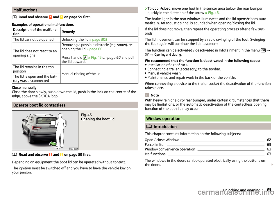
Operate boot lid contactless
Fig. 46
Opening the boot lid
Read and observe and on page 59 first.
Depending on equipment the boot lid can be operated without contact.
The ignition must be switched off and you have to have the vehicle key on
your person.
› To
open/close , move one foot in the sensor area below the rear bumper
quickly in the direction of the arrow » Fig. 46.
The brake light in the rear window illuminates and the lid opens/closes auto-
matically. An acoustic signal is sounded when opening/closing the lid.
If the lid does not move, then repeat the operating process after a few sec-
onds.
The lid movement can be stopped by a rapid swinging of the foot. Swinging
the foot again will continue the lid movement.
The function can be activated / deactivated in Infotainment in the menu
→
→
Opening and closing
.
We recommend that the function is deactivated in the following cases:
▶ Installation of a roof rack.
▶ Connecting a trailer (accessory) to the towbar.
▶ Manual vehicle wash.
▶ Maintenance and repair work in the back of the vehicle.
When connecting a device to the trailer socket the deactivation of the function
takes place.
Note
With heavy rain or a dirty rear bumper, under certain circumstances that there
may be limitations, or the automatic deactivation of the contactless opening
function of the boot lid may occur.
Window operation
Introduction
This chapter contains information on the following subjects:
Open / close Window
62
Force limiter
63
Window convenience operation
63
Malfunctions
63
The windows in the doors can be operated electrically using the buttons on
the doors.
61Unlocking and opening
Page 65 of 344
Force limiterRead and observe
and on page 62 first.
The electrical power windows are fitted with a force limiter.
If there is an obstacle, the closing process is stopped and the window goes
down by several centimetres.
If the obstacle prevents the window from being closed during the next 10 sec-
onds, the closing process is interrupted once again and the window goes down
by several centimetres.
If you attempt to close the window again within 10 seconds of the window be-
ing moved down for the second time, even though the obstacle was not yet
been removed, the closing process is only stopped. During this time it is not
possible to automatically close the window. The force limiter is still switched
on.
The force limiter is only not operational if you attempt to close the window
again within the next 10 seconds – the window will now close with full force!
If you wait longer than 10 seconds, the force limiter is switched on again.
Window convenience operation
Read and observe
and on page 62 first.
The convenience operation for the window offers the option to open/close all
the windows at once (or only the window in the driver's door). The function of
convenience operation can be individually adjusted in the Infotainment menu
→
→
Opening and closing
.
Opening
›
Press and hold the button on the key.
›
or:
Switch off the ignition, open the driver's door and hold the key
A
until it
stops in the open position » Fig. 47 on page 62 .
Closing
›
Press and hold the button on the key.
›
or:
Switch off the ignition, open the driver's door and hold the key
A
until it
stops in the closed position » Fig. 47 on page 62 .
›
In the KESSY system, hold your finger on the sensor on the outside of the
door handle of the front door » Fig. 36 on page 53 .
The convenience operation will only function correctly if all the windows auto-
matically open/close properly.
Convenience opening or closing the window using the key in the driver's door
locking cylinder is only possible within 45 seconds of locking the vehicle.
The movement of the window is stopped immediately when the respective
button is released.
Note
The settings for the window convenience operation are stored (depending on
the Infotainment type) in the active user account personalisation » page 50.
Malfunctions
Read and observe
and on page 62 first.
Repeatedly opening and closing the window can cause the window mecha-
nism to overheat and become temporarily blocked. You will be able to operate
the window again as soon as the operating mechanisms has cooled down.
After disconnecting the vehicle battery, automatic opening / closing of the
window can be deactivated. In this case, the system must be activated as fol-
lows.
Activate window operation
›
Switch-on the ignition.
›
Pull the top edge of the button and close the window.
›
Release the button.
›
Pull up the respective button and hold for 1 second.
Panoramic tilt / slide sunroof
Introduction
This chapter contains information on the following subjects:
Operation
64
Force limiter
64
Activate operation of the sliding/tilting roof
64
Electrically operated sunblind
65
Activating operation of the sunshade
65
63Unlocking and opening
Page 69 of 344
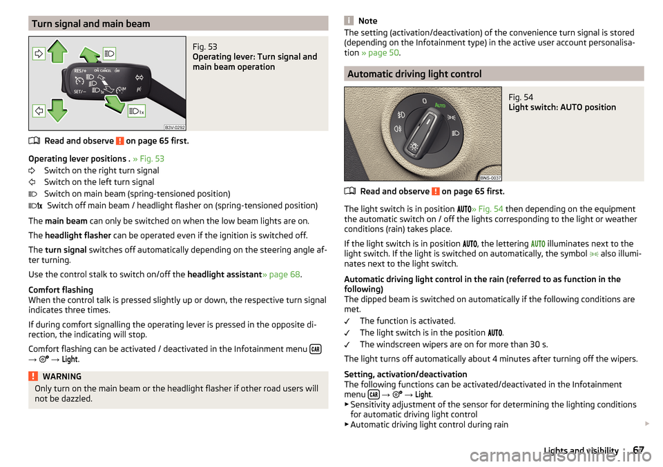
Turn signal and main beamFig. 53
Operating lever: Turn signal and
main beam operation
Read and observe on page 65 first.
Operating lever positions . » Fig. 53
Switch on the right turn signal
Switch on the left turn signal
Switch on main beam (spring-tensioned position) Switch off main beam / headlight flasher on (spring-tensioned position)
The main beam can only be switched on when the low beam lights are on.
The headlight flasher can be operated even if the ignition is switched off.
The turn signal switches off automatically depending on the steering angle af-
ter turning.
Use the control stalk to switch on/off the headlight assistant» page 68.
Comfort flashing
When the control talk is pressed slightly up or down, the respective turn signal
indicates three times.
If during comfort signalling the operating lever is pressed in the opposite di-
rection, the indicating will stop.
Comfort flashing can be activated / deactivated in the Infotainment menu
→
→
Light
.
WARNINGOnly turn on the main beam or the headlight flasher if other road users will
not be dazzled. NoteThe setting (activation/deactivation) of the convenience turn signal is stored
(depending on the Infotainment type) in the active user account personalisa-
tion » page 50 .
Automatic driving light control
Fig. 54
Light switch: AUTO position
Read and observe on page 65 first.
The light switch is in position
» Fig. 54 then depending on the equipment
the automatic switch on / off the lights corresponding to the light or weather
conditions (rain) takes place.
If the light switch is in position
, the lettering
illuminates next to the
light switch. If the light is switched on automatically, the symbol
also illumi-
nates next to the light switch.
Automatic driving light control in the rain (referred to as function in the
following)
The dipped beam is switched on automatically if the following conditions are
met.
The function is activated.
The light switch is in the position
.
The windscreen wipers are on for more than 30 s.
The light turns off automatically about 4 minutes after turning off the wipers.
Setting, activation/deactivation
The following functions can be activated/deactivated in the Infotainment
menu
→
→
Light
.
▶ Sensitivity adjustment of the sensor for determining the lighting conditions
for automatic driving light control
▶ Automatic driving light control during rain
67Lights and visibility
Page 70 of 344
CAUTIONPoorer visibility is evaluated by a sensor mounted below the windscreen in the
holder of the rear-view mirror. Do not cover the sensor - the system can be af-
fected.
Note
The setting (activate/deactivate) of the automatic driving light control during
rain is stored (depending on the Infotainment type) in the active user account
personalisation » page 50.
LED headlights
Read and observe
on page 65 first.
The LED headlights (hereinafter referred to as just system) use the journey da-ta to automatically ensure the best possible light cone in front of the vehicle.
The system will automatically operate in the following modes: urban, extra-ur-
ban, highway and mist. The static corning light provides for the illumination of
the road in the curve.
The system works as long as the light switch is in position
.
WARNINGIf there is a system malfunction the headlights are automatically lowered
to the emergency position, which prevents a possible dazzling of oncoming
traffic. This reduces the cone of light in front of the vehicle. Seek help from
a specialist garage.
Light Assist
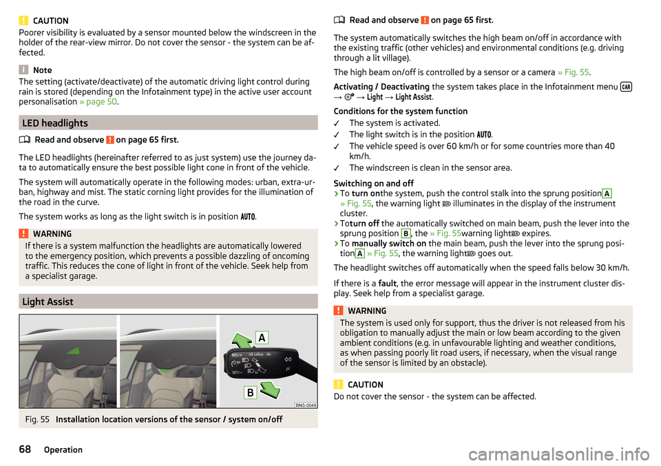
Fig. 55
Installation location versions of the sensor / system on/off
Read and observe on page 65 first.
The system automatically switches the high beam on/off in accordance with
the existing traffic (other vehicles) and environmental conditions (e.g. driving
through a lit village).
The high beam on/off is controlled by a sensor or a camera » Fig. 55.
Activating / Deactivating the system takes place in the Infotainment menu
→
→
Light
→
Light Assist
.
Conditions for the system function The system is activated.
The light switch is in the position .
The vehicle speed is over 60 km/h or for some countries more than 40
km/h.
The windscreen is clean in the sensor area.
Switching on and off
›
To turn on the system, push the control stalk into the sprung position
A
» Fig. 55 , the warning light
illuminates in the display of the instrument
cluster.
›
To turn off the automatically switched on main beam, push the lever into the
sprung position
B
, the » Fig. 55 warning light
expires.
›
To
manually switch on the main beam, push the lever into the sprung posi-
tion
A
» Fig. 55 , the warning light
goes out.
The headlight switches off automatically when the speed falls below 30 km/h.
If there is a fault, the error message will appear in the instrument cluster dis-
play. Seek help from a specialist garage.
WARNINGThe system is used only for support, thus the driver is not released from his
obligation to manually adjust the main or low beam according to the given
ambient conditions (e.g. in unfavourable lighting and weather conditions,
as when passing poorly lit road users, if necessary, when the visual range
of the sensor is limited by an obstacle).
CAUTION
Do not cover the sensor - the system can be affected.68Operation
Page 71 of 344
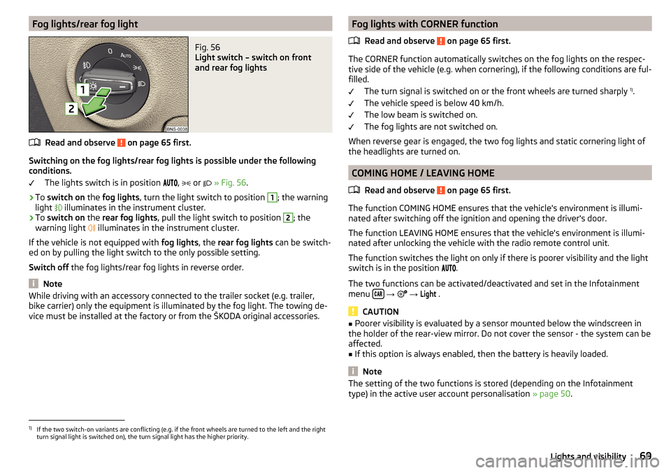
Fog lights/rear fog lightFig. 56
Light switch – switch on front
and rear fog lights
Read and observe on page 65 first.
Switching on the fog lights/rear fog lights is possible under the following
conditions.
The lights switch is in position ,
or
» Fig. 56 .
›
To switch on the fog lights , turn the light switch to position
1
; the warning
light illuminates in the instrument cluster.
›
To
switch on the rear fog lights , pull the light switch to position
2
; the
warning light illuminates in the instrument cluster.
If the vehicle is not equipped with fog lights, the rear fog lights can be switch-
ed on by pulling the light switch to the only possible setting.
Switch off the fog lights/rear fog lights in reverse order.
Note
While driving with an accessory connected to the trailer socket (e.g. trailer,
bike carrier) only the equipment is illuminated by the fog light. The towing de-
vice must be installed at the factory or from the ŠKODA original accessories.Fog lights with CORNER function
Read and observe
on page 65 first.
The CORNER function automatically switches on the fog lights on the respec-tive side of the vehicle (e.g. when cornering), if the following conditions are ful-
filled.
The turn signal is switched on or the front wheels are turned sharply 1)
.
The vehicle speed is below 40 km/h.
The low beam is switched on.
The fog lights are not switched on.
When reverse gear is engaged, the two fog lights and static cornering light of
the headlights are turned on.
COMING HOME / LEAVING HOME
Read and observe
on page 65 first.
The function COMING HOME ensures that the vehicle's environment is illumi-
nated after switching off the ignition and opening the driver's door.
The function LEAVING HOME ensures that the vehicle's environment is illumi-
nated after unlocking the vehicle with the radio remote control unit.
The function switches the light on only if there is poorer visibility and the light
switch is in the position .
The two functions can be activated/deactivated and set in the Infotainment
menu
→
→
Light
.
CAUTION
■
Poorer visibility is evaluated by a sensor mounted below the windscreen in
the holder of the rear-view mirror. Do not cover the sensor - the system can be
affected.■
If this option is always enabled, then the battery is heavily loaded.
Note
The setting of the two functions is stored (depending on the Infotainment
type) in the active user account personalisation » page 50.1)
If the two switch-on variants are conflicting (e.g. if the front wheels are turned to the left and the right
turn signal light is switched on), the turn signal light has the higher priority.
69Lights and visibility
Page 78 of 344
WARNING■The mirrors with automatic dimming contain electrolyte fluid which may
leak if the mirror glass is broken - this can irritate skin, eyes and the respi-
ratory system.■
If your eyes or skin come into contact with the electrolyte fluid, immedi-
ately wash the affected area for a few minutes with plenty of water. Seek
medical assistance if required.
Interior mirror dimming
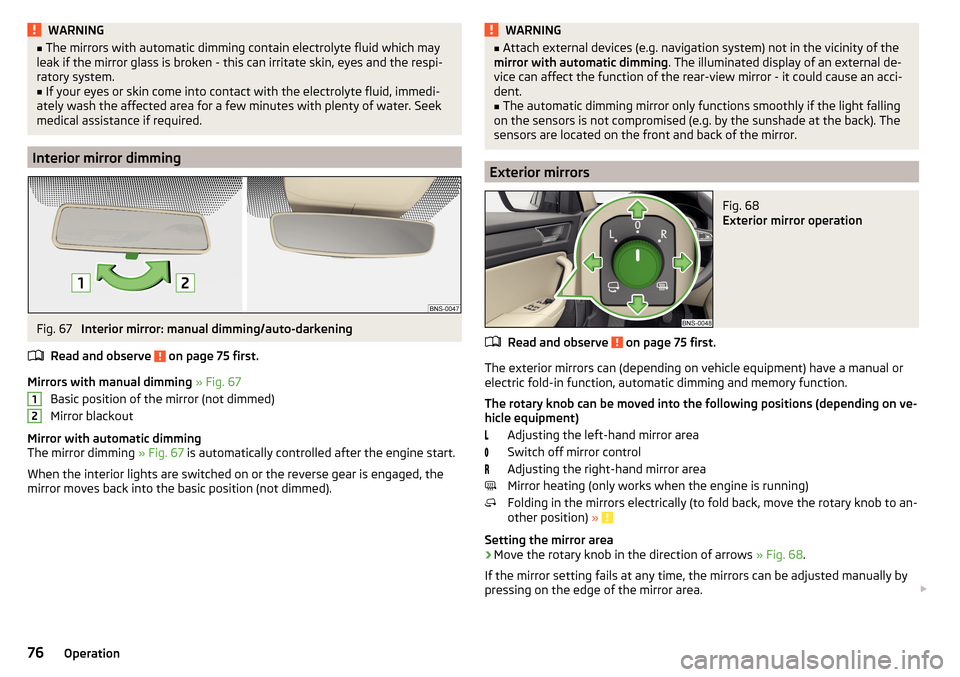
Fig. 67
Interior mirror: manual dimming/auto-darkening
Read and observe
on page 75 first.
Mirrors with manual dimming » Fig. 67
Basic position of the mirror (not dimmed)
Mirror blackout
Mirror with automatic dimming
The mirror dimming » Fig. 67 is automatically controlled after the engine start.
When the interior lights are switched on or the reverse gear is engaged, the
mirror moves back into the basic position (not dimmed).
12WARNING■ Attach external devices (e.g. navigation system) not in the vicinity of the
mirror with automatic dimming . The illuminated display of an external de-
vice can affect the function of the rear-view mirror - it could cause an acci-
dent.■
The automatic dimming mirror only functions smoothly if the light falling
on the sensors is not compromised (e.g. by the sunshade at the back). The
sensors are located on the front and back of the mirror.
Exterior mirrors
Fig. 68
Exterior mirror operation
Read and observe on page 75 first.
The exterior mirrors can (depending on vehicle equipment) have a manual or electric fold-in function, automatic dimming and memory function.
The rotary knob can be moved into the following positions (depending on ve- hicle equipment)
Adjusting the left-hand mirror area
Switch off mirror control
Adjusting the right-hand mirror area
Mirror heating (only works when the engine is running)
Folding in the mirrors electrically (to fold back, move the rotary knob to an-
other position) »
Setting the mirror area
›
Move the rotary knob in the direction of arrows » Fig. 68.
If the mirror setting fails at any time, the mirrors can be adjusted manually by
pressing on the edge of the mirror area.
76Operation
Page 113 of 344
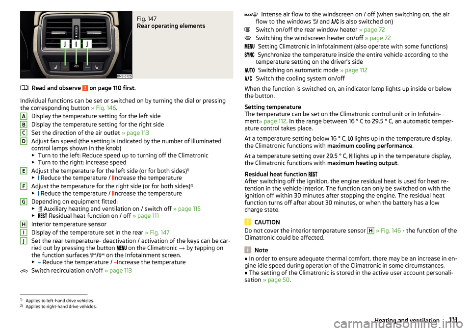
Fig. 147
Rear operating elements
Read and observe on page 110 first.
Individual functions can be set or switched on by turning the dial or pressingthe corresponding button » Fig. 146.
Display the temperature setting for the left side
Display the temperature setting for the right side
Set the direction of the air outlet » page 113
Adjust fan speed (the setting is indicated by the number of illuminated
control lamps shown in the knob)
▶ Turn to the left: Reduce speed up to turning off the Climatronic
▶ Turn to the right: Increase speed
Adjust the temperature for the left side (or for both sides) 1)
▶ Reduce the temperature /
Increase the temperature
Adjust the temperature for the right side (or for both sides) 2)
▶ Reduce the temperature /
Increase the temperature
Depending on equipment fitted:
▶ Auxiliary heating and ventilation on / switch off
» page 115
▶ Residual heat function on / off
» page 111
Interior temperature sensor
Display of the temperature set in the rear » Fig. 147
Set the rear temperature- deactivation / activation of the keys can be car-
ried out by pressing the button on the Climatronic
→ by tapping on
the function surfaces on the Infotainment screen.
▶ Reduce the temperature /
Increase the temperature
Switch recirculation on/off » page 113
ABCDEFGHIJIntense air flow to the windscreen on / off (when switching on, the air
flow to the windows and is also switched on)
Switch on/off the rear window heater » page 72
Switching the windscreen heater on/off » page 72
Setting Climatronic in Infotainment (also operate with some functions)
Synchronize the temperature inside the entire vehicle according to the
temperature setting on the driver's side
Switching on automatic mode » page 112
Switch the cooling system on/off
When the function is switched on, an indicator lamp lights up inside or below the button.
Setting temperature
The temperature can be set on the Climatronic control unit or in Infotain-
ment » page 112 . In the range between 16 ° C to 29.5 ° C, an automatic temper-
ature control takes place.
At a temperature setting below 16 ° C, lights up in the temperature display,
the Climatronic functions with maximum cooling performance .
At a temperature setting over 29.5 ° C, lights up in the temperature display,
the Climatronic functions with maximum heating output.
Residual heat function
After switching off the ignition, the engine residual heat is used for heat re-
tention in the vehicle interior. The function can only be switched on with the
ignition off within 30 minutes after stopping the engine. The residual heat
function turns off after about 30 minutes, or when the battery has a low
charge state.
CAUTION
Do not cover the interior temperature sensor H » Fig. 146 - the function of the
Climatronic could be affected.
Note
■ In order to ensure adequate thermal comfort, there may be an increase in en-
gine idle speed during operation of the Climatronic in some circumstances.■
The setting of the Climatronic is stored in the active user account personali-
sation » page 50 .
1)
Applies to left-hand drive vehicles.
2)
Applies to right-hand drive vehicles.
111Heating and ventilation