sensor SKODA KODIAQ 2016 1.G User Guide
[x] Cancel search | Manufacturer: SKODA, Model Year: 2016, Model line: KODIAQ, Model: SKODA KODIAQ 2016 1.GPages: 344, PDF Size: 58.96 MB
Page 115 of 344
Air distribution controlRead and observe
on page 110 first.
The recirculation mode prevents contaminated outside air getting into the In-terior of the vehicle. In recirculated air mode air is sucked out of the interior of
the vehicle and then fed back into the interior.
›
To switch on , press the
button. The warning light below the button lights
up.
›
To switch off , press the
button again. The warning light below the button
goes out.
Heating and manual air conditioning system
If the air distribution control is set to position when the recirculation modes
is switched on, the recirculated-air mode is switched off. By pressing the
button, the air recirculation also in this position can be switched on again.
When the cooling system (button ) is switched on and the temperature reg-
ulator is “turned” to the left, the recirculated-air mode is switched on.
Climatronic
The Climatronic can have a sensor that measures the air recirculation mode and automatically turns on if there is an increased concentration of pollutants
in the incoming air.
When the pollutant concentration decreases to the normal level, the recircula-
ted air mode is automatically switched off.
Automatically switch on / off the air recirculation function can be set in the In-
fotainment screen. by pressing the button on the Climatronic and by sub-
sequently pressing the function surfaces
→
Automatic air recirculation
. Auto-
matic power on / off function at a temperature above 2 ° C.
A shut-off of the air recirculation function is carried out by pressing the
button, possibly depending on the moisture conditions in the vehicle interior.
WARNINGThe air recirculation cannot be switched on for a longer period of time be-
cause there is no supply of fresh air from the outside. “Stale air” may result
in fatigue in the driver and occupants, reduce attention levels and also
cause the windows to mist up. As soon as the windows mist up, turn the air
recirculation mode off immediately - there is a risk of accident!CAUTIONWe recommend not smoking in the vehicle when the recirculating air operation
is switched on. The smoke sucked from inside the vehicle is deposited on the
evaporator of the air conditioner. This produces a permanent odour when the
air conditioning system is operating which can only be eliminated through con-
siderable effort and expense (replacement of compressor).
Air outlet vents
Fig. 150
Air vents at the front
Fig. 151
Air vents at the rear
Read and observe
on page 110 first.
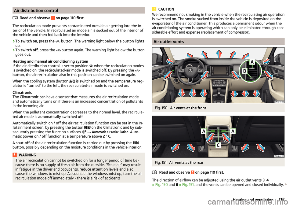
The direction of airflow can be adjusted using the air outlet vents 3, 4
» Fig. 150 and 6 » Fig. 151 , and the vents can be opened and closed individually.
113Heating and ventilation
Page 133 of 344
■Touchscreen tone - Switch on/off audible tone when touching the screen
■No navigation sound during call
- Switching on / off the nav. announcements dur-
ing a telephone call (not applicable to Infotainment Bolero)
Display settings
›
Press the button, then tap on the function surface
Tap →
Screen
.
■
Switch off screen (in 10 seconds)
- Enable / disable the automatic power off func-
tion
■
Brightness:
- Adjusts the brightness of the screen
■
Touchscreen tone
- Switch on/off audible tone when touching the screen
■
Menu button tone
- Turn on / off the acoustic signal by pressing a button next
to the screen
■
Animation when finger near screen
- Turn the proximity sensors on/off (When the
function is on, e.g. Navigation will be shown in the main menu when moving a
finger towards the bottom bar with the function surfaces on the screen)
■
Show clock in standby mode
- Time and date displayed on the screen when the
ignition is switched on and Infotainment is switched off
Time and date settings
›
Press the button, then tap on the function surface
→
Time and date
.
■
Clock time Source:
- Settings of the clock time source: manual / GPS (applies to
the infotainment Columbus, Amundsen)
■
Time:
- Time Settings
■
Summer time
- Switches the summer time on/off
■
Automatic summertime
- Turn on / off the automatic switch to daylight saving
time
■
Time zone:
- Choice of time zone
■
Time Format:
- Specify the time format
■
Date:
- Date Settings
■
Date format:
- Setting the date format
Setting the Infotainment language
›
Press the button, then tap on the function surface
→
Language
.
›
Select the Infotainment language.
In some languages, after selecting the function surface
Female
and
Male
are dis-
played for the choice of voice prompts for Infotainment.
Note■ When a language is selected which does not support voice control, Infotain-
ment will indicate this with a message on the screen.■
The messages are generated by Infotainment. Flawless clarity (e.g. road or
city name) cannot always be guaranteed.
Additional keypad language settings
›
Press the button, then tap on the function surface
→
Additional keypadlanguages
.
In this menu, a keyboard language set can be added to allow the entering of
characters other than those in the currently selected language (function sur-
face ).
Unit settings
›
Press the button, then tap on the function surface
→
Units
.
■
Distance:
- Distance units
■
Speed:
- Speed units
■
Temperature:
- Temperature units
■
Volume:
- Volume units
■
Consumption:
- Consumption units
■
Pressure:
- Printing units for tyre pressure
Setting data transfer
An active data transfer allows data transfer between Infotainment and the ex-
ternal device (e.g. MirrorLink® application) or the operation of some Infotain-
ment functions using the application of the external device (e.g. ŠKODA Media
Command).
›
Press the button, then tap on the function surface
→
Mobile device datatransfer
.
■
Activate data transfer for ŠKODA apps
- Turning data transfer on and off
■
Use apps to operate::
- Setting Infotainment operation via the applications of the
external device (applies to Infotainment Columbus, Amundsen) ■
Deactivate
- Deactivation of Infotainment operation via an external device
■
Confirm
- Infotainment operation with required confirmation
■
Allow
- Infotainment operation without required confirmation
131Infotainment settings - Columbus, Amundsen, Bolero
Page 180 of 344
Navigation
Introductory information
Navigation - function sequence
Applies to Infotainment Columbus, Amundsen.
Route guidance is started as follows.
›
Search for/ enter a new destination or Select one of the stored destinations.
›
Confirm the route calculation in the destination details or if necessary, adjust
the route options.
›
Select the preferred route type, if this is requested by Infotainment.
A route calculation occurs and route guidance starts.
The route guidance is provided by graphical driving recommendations and nav. announcements.
The is an option to add additional destinations during route guidance, or to
adapt the route.
If a traffic radio station is available, information concerning traffic delays is
evaluated by Infotainment and, if necessary, an alternative route is offered.
If you deviate from the route, then a new route calculation is carried out.
GPS satellite signal
Infotainment uses the GPS (Global Positioning System) satellite signal for
route guidance.
Outside the range of the GPS satellite signal (e.g. in dense vegetation, in tun-
nels, parking garages, etc.), Infotainment navigates only with restrictions using
vehicle sensors.
The unit offers the possibility to show in the split screen display the following
Position
» Fig. 222 on page 181 information about the current geographical po-
sition of the vehicle and the satellite signal.
Geographical longitude
Geographical latitude
Elevation
Number of received/available satellites
If no GPS satellite signal is available, no values are displayed.
Navigation data
Navigation data source Columbus
The navigation data is stored in the Infotainment memory.
Navigation data source Amundsen
The navigation data is stored on an Original SD Card.
In order to ensure the function of the navigation, the Original SD card, with the
navigation data, must be inserted in the respective slot in the external module
» page 123 .
If the original SD card is damaged or lost, a new original SD card can be pur-
chased from the ŠKODA Original Accessories.
With a Non-original SD Card, navigation does not work .
Determining the version of the navigation data›
In the Navigation main menu, tap the function surface
Tap
→
Version infor-mation
.
Update navigation data
We recommend that you update the navigation data on a regular basis (e.g.
Due to newly developed roads and changed traffic signs).
The information on updating the navigation data is to be obtained from a
ŠKODA partner or on the following ŠKODA Internet pages.
http://go.skoda.eu/updateportal
Update navigation data online
When activated online services infotainment online » page 118 can the naviga-
tion data for the infotainment Columbus Updating online » page 179, Naviga-
tion data and POI categories Import / Update online ,
If an update of the navigation data for the current vehicle position or the desti-
nation of the route is available, which in this regard from a Infotainment auto-
matic Note issued and offered an upgrade option.
An online update of navigation data is also manually feasible as follows.
▶ In the Navigation main menu, tap the function surface
→
version information
→
→
Update (online)
→
Map update
Tap.
▶ The Select / the desired country / region.
▶ Tap on the function surface
Retrieve
.
During the upgrade process, infotainment is usable without limitation.
178Infotainment
Page 217 of 344
Assist systems
General information
Introduction
This chapter contains information on the following subjects:
Radar sensor
215WARNING■ The assistance systems only serve to support the driver and do not re-
lieve the driver of the responsibility for driving the vehicle.■
The increased safety provision, as well as the increased occupant protec-
tion provided by the assistance systems must not tempt you to take risks -
risk of accident!
■
Adjust the speed and driving style to the current visibility, weather, road
and traffic conditions.
■
The assistance systems have physical and system-related limitations. For
this reason, the driver may experience some undesired or delayed system
responses in certain situations. You should therefore always be alert and
ready to intervene!
■
Only enable, disable or set the assistance systems when you have the car
fully under control, in every traffic situation - risk of accident!
Radar sensor
Fig. 264
Installation location of the radar
sensor
Read and observe on page 215 first.
The radar sensor (hereinafter referred to only sensor) uses electromagnetic
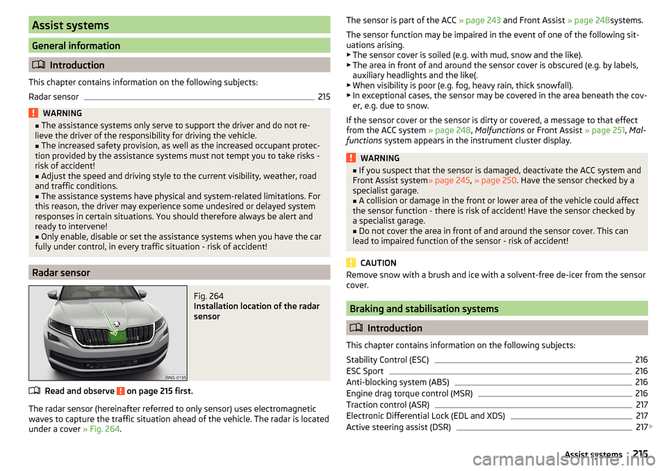
waves to capture the traffic situation ahead of the vehicle. The radar is located
under a cover » Fig. 264.
The sensor is part of the ACC » page 243 and Front Assist » page 248systems.
The sensor function may be impaired in the event of one of the following sit-
uations arising. ▶ The sensor cover is soiled (e.g. with mud, snow and the like).
▶ The area in front of and around the sensor cover is obscured (e.g. by labels,
auxiliary headlights and the like(.
▶ When visibility is poor (e.g. fog, heavy rain, thick snowfall).
▶ In exceptional cases, the sensor may be covered in the area beneath the cov-
er, e.g. due to snow.
If the sensor cover or the sensor is dirty or covered, a message to that effect
from the ACC system » page 248, Malfunctions or Front Assist » page 251, Mal-
functions system appears in the instrument cluster display.WARNING■
If you suspect that the sensor is damaged, deactivate the ACC system and
Front Assist system » page 245, » page 250 . Have the sensor checked by a
specialist garage.■
A collision or damage in the front or lower area of the vehicle could affect
the sensor function - there is risk of accident! Have the sensor checked by
a specialist garage.
■
Do not cover the area in front of and around the sensor cover. This can
lead to impaired function of the sensor - risk of accident!
CAUTION
Remove snow with a brush and ice with a solvent-free de-icer from the sensor
cover.
Braking and stabilisation systems
Introduction
This chapter contains information on the following subjects:
Stability Control (ESC)
216
ESC Sport
216
Anti-blocking system (ABS)
216
Engine drag torque control (MSR)
216
Traction control (ASR)
217
Electronic Differential Lock (EDL and XDS)
217
Active steering assist (DSR)
217
215Assist systems
Page 223 of 344
Activation / deactivation223Automatic system activation when moving forward223
Automatic emergency braking
223
The parking aid (hereinafter referred to as system) uses acoustic signals or In-
fotainment screen when manoeuvring around obstacles in the vicinity of the
vehicle.
WARNING■ The general information relating to the use of assistance systems must
be observed » page 215, in section Introduction .■
Moving persons or objects may not be recognized by the system sensors.
■
Under certain circumstances, surfaces of certain objects and types of
clothing cannot reflect the system signals. There is a danger that such ob-
jects or people may not be recognised by the system sensors.
■
External noise sources may affect the signals of the system sensors.
There is a danger that obstacles may not be detected by the system sen-
sors.
■
Before reversing, make sure that there are is not any small obstacle, such
as a rock, thin post etc., in front of or behind your vehicle. Such obstacles
may not be recognised by the system sensors.
CAUTION
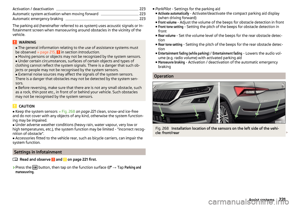
■ Keep the system sensors » Fig. 268 on page 221 clean, snow-and ice-free
and do not cover with any objects of any kind, otherwise the system function-
ing may be impaired.■
Under adverse weather conditions (heavy rain, water vapour, very low or
high temperatures, etc.), the system function may be limited - “incorrect recog-
nition of obstacle”.
■
Accessories fitted to the vehicle rear, such as bicycle carriers, can impair the
system function.
Settings in Infotainment
Read and observe
and on page 221 first.
›
Press the button, then tap on the function surface
→ Tap
Parking andmanoeuvring
.
■
ParkPilot - Settings for the parking aid
■Activate automatically
- Activate/deactivate the compact parking aid display
(when driving forward)
■
Front volume
- Adjust the volume of the beeps for obstacle detection in front
■
Front tone setting
- Setting the pitch of the beeps for obstacle detection in
front
■
Rear volume
- Set the volume level of the beeps for the rear obstacle detec-
tion
■
Rear tone setting
- Setting the pitch of the beeps for the rear obstacle detec-
tion
■
Entertainment fading (while parking)
/
Entertainment fading
- Lowers the audio vol-
ume (e.g. radio volume) with activated parking aid
■
Manoeuvre braking
- Activation / deactivation of the automatic emergency
braking
Operation
Fig. 268
Installation location of the sensors on the left side of the vehi-
cle: front/rear
221Assist systems
Page 224 of 344
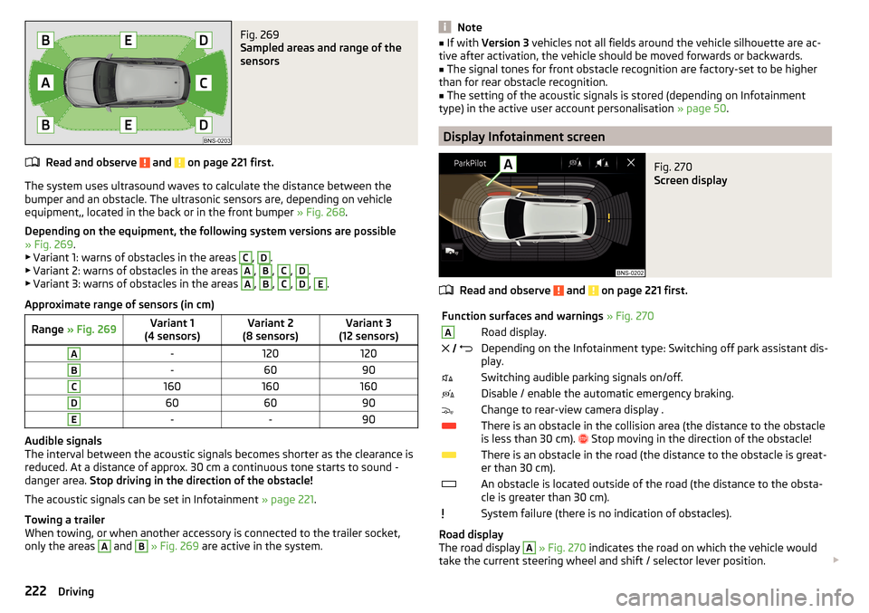
Fig. 269
Sampled areas and range of the
sensors
Read and observe and on page 221 first.
The system uses ultrasound waves to calculate the distance between the
bumper and an obstacle. The ultrasonic sensors are, depending on vehicle
equipment,, located in the back or in the front bumper » Fig. 268.
Depending on the equipment, the following system versions are possible
» Fig. 269 .
▶ Variant 1: warns of obstacles in the areas
C
,
D
.
▶ Variant 2: warns of obstacles in the areas
A
,
B
,
C
,
D
.
▶ Variant 3: warns of obstacles in the areas
A
,
B
,
C
,
D
,
E
.
Approximate range of sensors (in cm)
Range » Fig. 269Variant 1
(4 sensors)Variant 2
(8 sensors)Variant 3
(12 sensors)A-120120B-6090C160160160D606090E--90
Audible signals
The interval between the acoustic signals becomes shorter as the clearance is
reduced. At a distance of approx. 30 cm a continuous tone starts to sound -
danger area. Stop driving in the direction of the obstacle!
The acoustic signals can be set in Infotainment » page 221.
Towing a trailer
When towing, or when another accessory is connected to the trailer socket,
only the areas
A
and
B
» Fig. 269 are active in the system.
Note■
If with Version 3 vehicles not all fields around the vehicle silhouette are ac-
tive after activation, the vehicle should be moved forwards or backwards.■
The signal tones for front obstacle recognition are factory-set to be higher
than for rear obstacle recognition.
■
The setting of the acoustic signals is stored (depending on Infotainment
type) in the active user account personalisation » page 50.
Display Infotainment screen
Fig. 270
Screen display
Read and observe and on page 221 first.
Function surfaces and warnings » Fig. 270ARoad display. Depending on the Infotainment type: Switching off park assistant dis-
play.Switching audible parking signals on/off.Disable / enable the automatic emergency braking.Change to rear-view camera display .There is an obstacle in the collision area (the distance to the obstacle
is less than 30 cm).
Stop moving in the direction of the obstacle!There is an obstacle in the road (the distance to the obstacle is great-
er than 30 cm).An obstacle is located outside of the road (the distance to the obsta-
cle is greater than 30 cm).System failure (there is no indication of obstacles).
Road display
The road display
A
» Fig. 270 indicates the road on which the vehicle would
take the current steering wheel and shift / selector lever position.
222Driving
Page 226 of 344
After switching the ignition on and off, the systems remains activated / deacti-
vated depending on the setting prior to switching off the ignition.
The brake function can also be deactivated once with the function surface
» Fig. 270 on page 222 .
Rear traffic alert and wizard for “Blind spot”Monitoring
Introduction
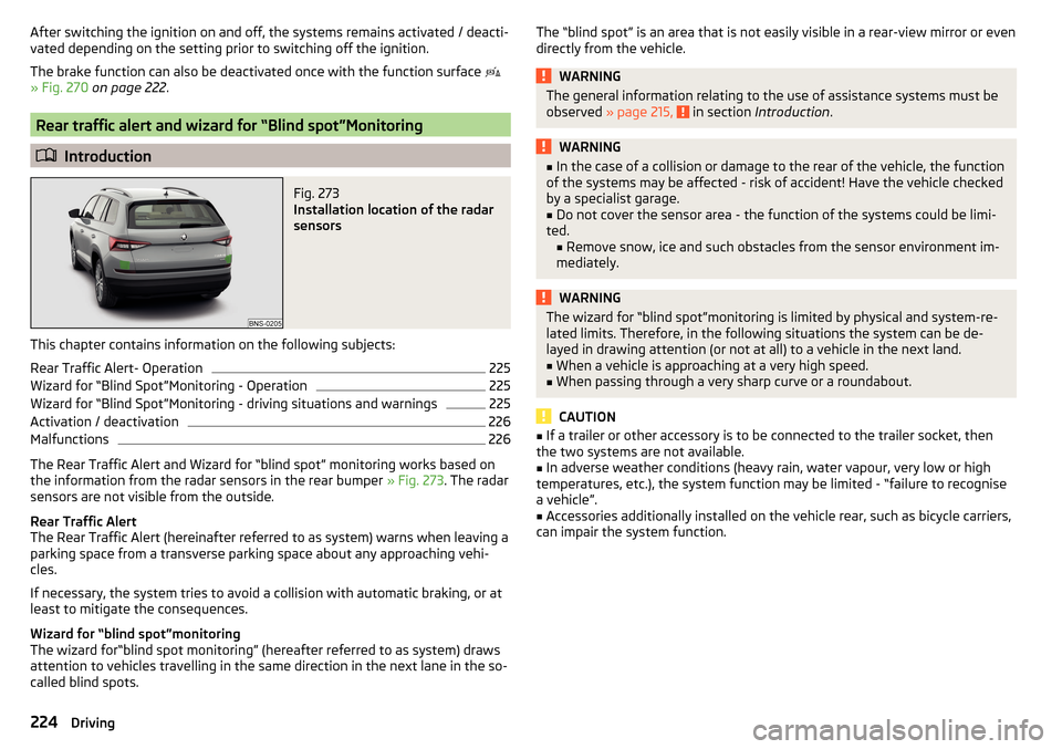
Fig. 273
Installation location of the radar
sensors
This chapter contains information on the following subjects:
Rear Traffic Alert- Operation
225
Wizard for “Blind Spot”Monitoring - Operation
225
Wizard for “Blind Spot”Monitoring - driving situations and warnings
225
Activation / deactivation
226
Malfunctions
226
The Rear Traffic Alert and Wizard for “blind spot” monitoring works based on
the information from the radar sensors in the rear bumper » Fig. 273. The radar
sensors are not visible from the outside.
Rear Traffic Alert
The Rear Traffic Alert (hereinafter referred to as system) warns when leaving a
parking space from a transverse parking space about any approaching vehi-
cles.
If necessary, the system tries to avoid a collision with automatic braking, or at
least to mitigate the consequences.
Wizard for “blind spot”monitoring
The wizard for“blind spot monitoring” (hereafter referred to as system) draws
attention to vehicles travelling in the same direction in the next lane in the so-
called blind spots.
The “blind spot” is an area that is not easily visible in a rear-view mirror or even
directly from the vehicle.WARNINGThe general information relating to the use of assistance systems must be
observed » page 215, in section Introduction .WARNING■
In the case of a collision or damage to the rear of the vehicle, the function
of the systems may be affected - risk of accident! Have the vehicle checked
by a specialist garage.■
Do not cover the sensor area - the function of the systems could be limi-
ted. ■ Remove snow, ice and such obstacles from the sensor environment im-
mediately.
WARNINGThe wizard for “blind spot”monitoring is limited by physical and system-re-
lated limits. Therefore, in the following situations the system can be de-
layed in drawing attention (or not at all) to a vehicle in the next land.■
When a vehicle is approaching at a very high speed.
■
When passing through a very sharp curve or a roundabout.
CAUTION
■ If a trailer or other accessory is to be connected to the trailer socket, then
the two systems are not available.■
In adverse weather conditions (heavy rain, water vapour, very low or high
temperatures, etc.), the system function may be limited - “failure to recognise
a vehicle”.
■
Accessories additionally installed on the vehicle rear, such as bicycle carriers,
can impair the system function.
224Driving
Page 227 of 344
Rear Traffic Alert- OperationFig. 274
Infotainment screen: Warning indicator / driving situation
Read and observe
and on page 224 first.
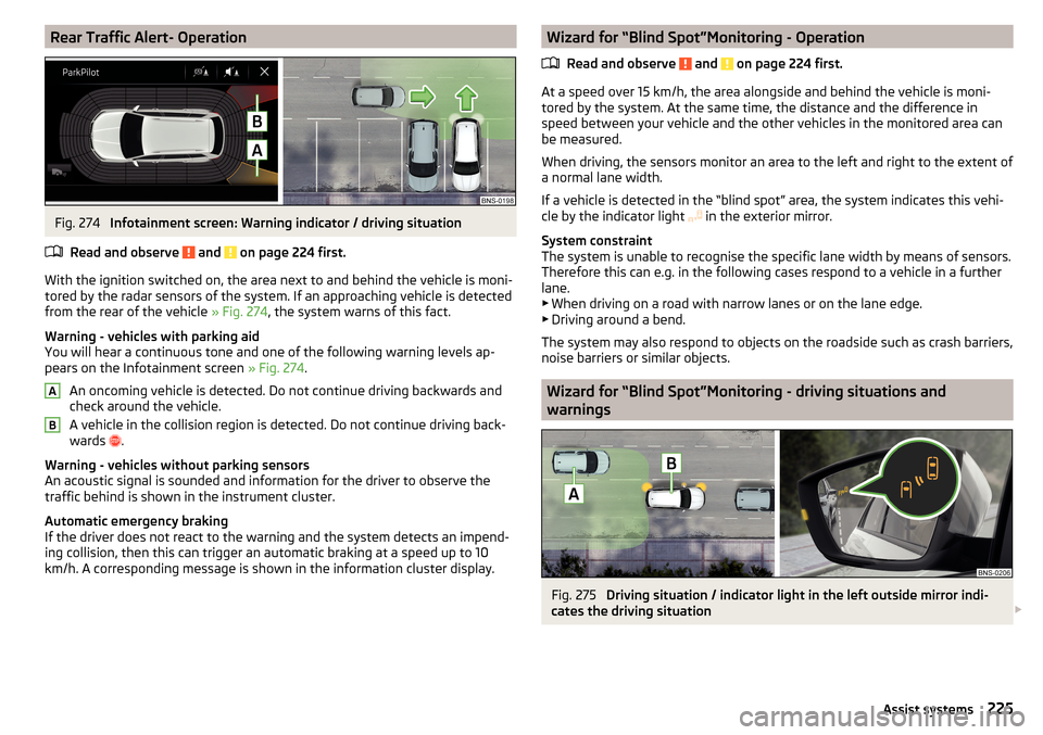
With the ignition switched on, the area next to and behind the vehicle is moni-
tored by the radar sensors of the system. If an approaching vehicle is detected
from the rear of the vehicle » Fig. 274, the system warns of this fact.
Warning - vehicles with parking aid
You will hear a continuous tone and one of the following warning levels ap-
pears on the Infotainment screen » Fig. 274.
An oncoming vehicle is detected. Do not continue driving backwards and
check around the vehicle.
A vehicle in the collision region is detected. Do not continue driving back-
wards .
Warning - vehicles without parking sensors
An acoustic signal is sounded and information for the driver to observe the
traffic behind is shown in the instrument cluster.
Automatic emergency braking
If the driver does not react to the warning and the system detects an impend-
ing collision, then this can trigger an automatic braking at a speed up to 10
km/h. A corresponding message is shown in the information cluster display.
ABWizard for “Blind Spot”Monitoring - Operation
Read and observe
and on page 224 first.
At a speed over 15 km/h, the area alongside and behind the vehicle is moni-
tored by the system. At the same time, the distance and the difference in
speed between your vehicle and the other vehicles in the monitored area can
be measured.
When driving, the sensors monitor an area to the left and right to the extent of
a normal lane width.
If a vehicle is detected in the “blind spot” area, the system indicates this vehi-
cle by the indicator light in the exterior mirror.
System constraint
The system is unable to recognise the specific lane width by means of sensors.
Therefore this can e.g. in the following cases respond to a vehicle in a further
lane.
▶ When driving on a road with narrow lanes or on the lane edge.
▶ Driving around a bend.
The system may also respond to objects on the roadside such as crash barriers,
noise barriers or similar objects.
Wizard for “Blind Spot”Monitoring - driving situations and
warnings
Fig. 275
Driving situation / indicator light in the left outside mirror indi-
cates the driving situation
225Assist systems
Page 228 of 344
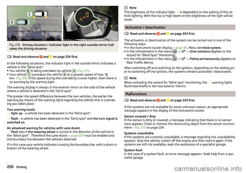
Fig. 276
Driving situation / indicator light in the right outside mirror indi-
cates the driving situation
Read and observe
and on page 224 first.
In the following situations, the indicator light in the outside mirror indicates avehicle in the “blind spot”.
▶ You vehicle
B
is being overtaken by vehicle
A
» Fig. 275 .
▶ Your vehicle
C
overtakes the vehicle
D
at a greater speed of max. 10
km » Fig. 276 . If the speed during the overtaking is even higher, then there is
no warning by the warning light.
The warning display is always in the exterior mirror on the side of the vehicle where a vehicle is detected in the “blind spot”.
The greater the speed difference between the two vehicles, the earlier the
warning (by means of the warning light) regarding the vehicle that is overtak-
ing you takes place.
Two warning levels
light up - a vehicle has been detected in the “blind spot”.
flash - a vehicle has been detected in the “blind spot” and the turn signal is
switched on .
An advanced warning for vehicles with Lane Assist
flash also if the steering wheel is turned in the direction of the vehicle in
the “blind spot” . Therefore the Lane Assist » page 254 must be enabled and
the boundary line between the vehicles detected.
If in this case your vehicle indicates crossing the boundary line, with a short vi-
bration of the steering wheel.
NoteThe brightness of the indicator light is dependent on the setting of the ve-
hicle lighting. With the low or high beam on the brightness of the light will be
lower.
Activation / deactivation
Read and observe
and on page 224 first.
The activation or deactivation of the system can be carried out in one of the
following ways. ▶ In the instrument cluster display » page 49, Menu item
Assist systems
.
▶ In the Infotainment in the menu
→
→
Driver assistance
(Applies to the
wizard for “Blind Spot” Monitoring).
▶ In the Infotainment in the menu
→
→
Parking and manoeuvring
(Applies to
Rear Traffic Alerts).
After switching off and switching on the ignition, depending on the setting pri-
or to switching off the ignition, the systems remains activated / deactivated.
Note
When activating the wizard for “blind spot” monitoring, the warning lights
illuminate briefly in the two exterior mirrors.
Malfunctions
Read and observe
and on page 224 first.
If the systems are not available for some unknown reason, an appropriate
message appears in the display of the instrument cluster.
Sensor covered / dirty
If the sensor is dirty or covered, a message indicating that there is no sensor
view appears. Clean or remove the obstructing object from the sensor environ-
ment » Fig. 273 on page 224 .
Systems unavailable
If the systems are currently unavailable, a message regarding the unavailability
appears. Stop the vehicle, switch off the engine and then start it again. If the
systems are still not available, seek the assistance of a specialist garage.
System fault
In the case of a system fault, an error message appears. Seek help from a spe-
cialist garage.
226Driving
Page 229 of 344
Rear View Camera
Introduction
This chapter contains information on the following subjects:
Operating principle
227
Activation/deactivation
228
Function surfaces
228
Orientation lines and lane
228
Mode - traverse parking
229
Mode - parallel parking
229
Mode - driving up to a trailer / distance monitoring
230
Mode - monitor the area behind the vehicle
230
The rear view camera (following as system) helps the driver when parking and
manoeuvring by displaying the area behind the vehicle on Infotainment screen
(hereinafter only known as screen).
There are four modes available for different situations during the park and ma-
noeuvring action. The mode change is carried out using the function surfaces
on the screen » page 228.
WARNING■
The general information relating to the use of assistance systems must
be observed » page 215, in section Introduction .■
The system detects obstacles. The display of the auxiliary boxes and lines
is independent of the actual vehicle environment. The driver must judge for
themselves whether the vehicle can park safely in the selected parking
space.
■
The camera may not be soiled or obscured, otherwise the system function
will be significantly affected - there is a risk of accident. For information on
cleaning » page 271 .
CAUTION■
The camera image is distorted by contrast with eyesight. For this reason, the
screen display is only of limited use for estimating distances to following vehi-
cles.■
Some items, such as thin posts, chain link fences, grilles or uneven road sur-
faces may not be properly displayed in terms of screen resolution.
■
In a crash or damage the vehicle's rear camera can possibly deviate from the
correct position. If this is the case, have the sensor checked by a specialist ga-
rage.
Note
The camera is equipped with a cleaning system » page 75. The spraying is car-
ried out automatically when the rear window is sprayed.
Operating principle
Fig. 277
Installation location of the camera / scanned area behind the ve-
hicle
Read and observe
and on page 227 first.
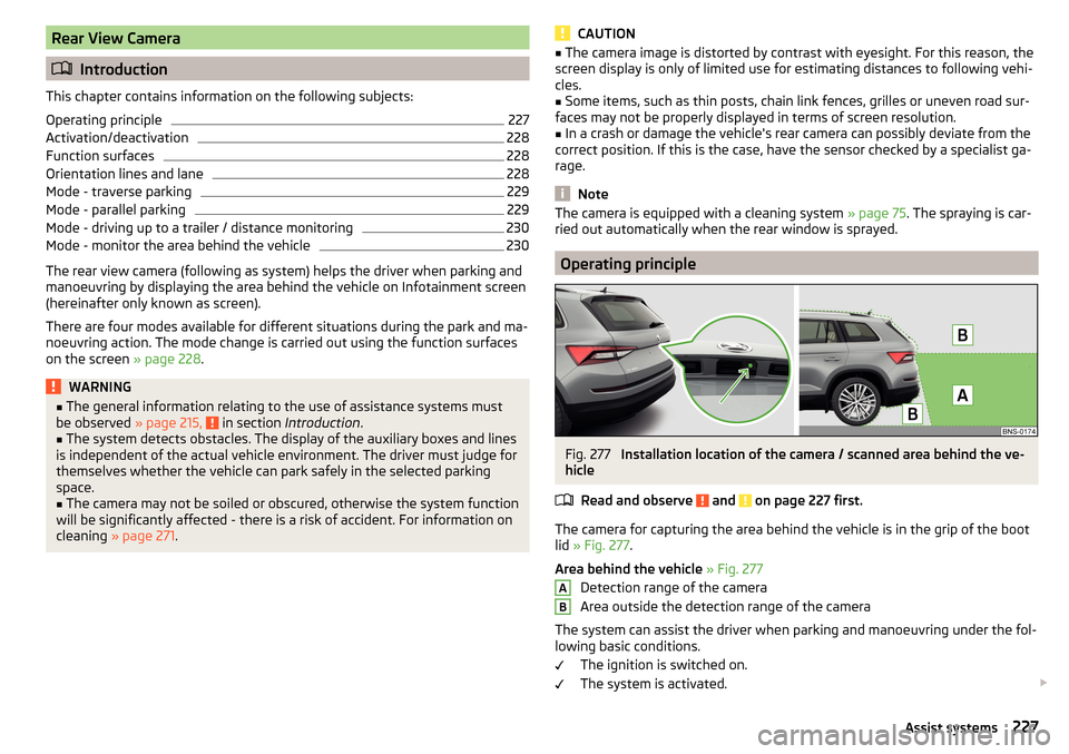
The camera for capturing the area behind the vehicle is in the grip of the bootlid » Fig. 277 .
Area behind the vehicle » Fig. 277
Detection range of the camera
Area outside the detection range of the camera
The system can assist the driver when parking and manoeuvring under the fol- lowing basic conditions.
The ignition is switched on.
The system is activated.
AB227Assist systems