child lock SKODA KODIAQ 2016 1.G Owner's Manual
[x] Cancel search | Manufacturer: SKODA, Model Year: 2016, Model line: KODIAQ, Model: SKODA KODIAQ 2016 1.GPages: 344, PDF Size: 58.96 MB
Page 4 of 344
Table of Contents
Liability for defects and ŠKODA warranty for
new cars5
Printed Owner's Manual
7
Online Owner's Manual
8
Notes
9
Structure of the Owner´s Manual and further
information
10
Abbreviations
Safety
Passive Safety
12
General information
12
Correct and safe seated position
12
emergency call
14
Seat belts
15
Using seat belts
15
Inertia reel and belt tensioners
18
Airbag system
19
Description of the airbag system
19
Airbag deactivation
22
Transporting children safely
23
Child seat
23
Fastening systems
27
Operation
Cockpit
31
Overview
30
Instruments and warning lights
32
Instrument cluster
32
Warning lights
33Information system43Driver information system43
Operation of the information system
45
Driving data (Multifunction display)
46
MAXI DOT display
48
Service interval display
49
Personalization
50
Unlocking and opening
52
Unlocking and locking
52
Anti-theft alarm system
57
Manually operated tailgate
58
Electric boot lid
59
Window operation
61
Panoramic tilt / slide sunroof
63
Lights and visibility
65
Light
65
Interior lighting
71
Viisibility
72
Windscreen wipers and washers
73
Rear view mirror
75
Seats and head restraints
78
Front seats
78
Rear seats
80
Headrests
83
Seat heating and ventilation
85
Heated steering wheel
86
Practical features
87
Interior equipment
87
Electrical sockets
96
Ashtray and cigarette lighter
98
Tablet holder
99Transport of cargo100Luggage compartment100
Variable loading floor in the luggage
compartment (Estate)
106
Transportation on the roof rack
108
Heating and ventilation
109
Heating, manual air conditioning system,
Climatronic
109
Auxiliary heating (auxiliary heating and
ventilation)
114
Online services ŠKODA Connect
117
Introductory information
117
Care Connect-Services
118
infotainment online-Services
118
Infotainment
Introductory information
120
Important information
120
Infotainment Overview
121
Infotainment operation
124
Infotainment operation
124
Voice control
127
Updating the Infotainment software
129
Infotainment settings - Columbus, Amundsen,
Bolero
130
Infotainment system settings
130
Radio menu settings
133
Media menu settings
134
Image menu settings
134
Video DVD menu settings
134
Settings
134
SmartLink menu settings
136
Navigation menu settings
1362Table of Contents
Page 15 of 344
WARNING■The front seats and all head restraints must be adjusted to match the
body size at all times and the seat belt must always be fastened properly to
provide the most effective levels of protection to the passengers.■
Each occupant must correctly fasten the seat belt belonging to the seat.
Children must be fastened » page 23, Transporting children safely with a
suitable restraint system.
■
The seat backrests must not be tilted too far back when driving, as this
will impair the function of the seat belts and of the airbag system – risk of
injury!
WARNINGBy sitting incorrectly, the occupant is risking life-threatening injuries.
Driver’s correct seated position
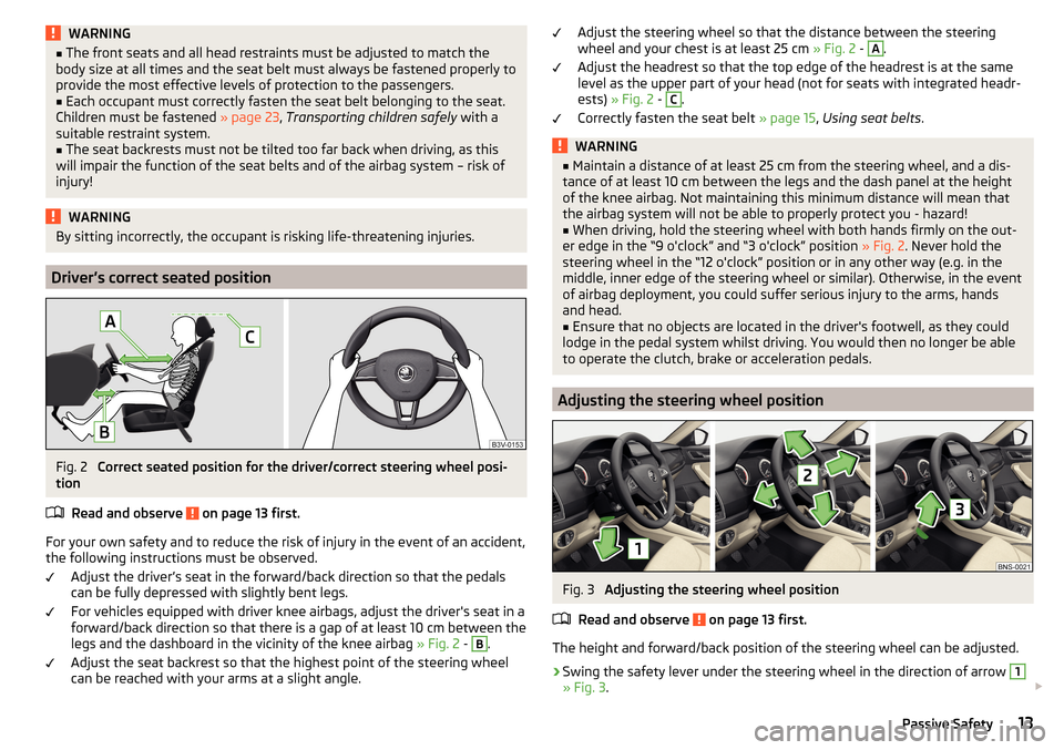
Fig. 2
Correct seated position for the driver/correct steering wheel posi-
tion
Read and observe
on page 13 first.
For your own safety and to reduce the risk of injury in the event of an accident,
the following instructions must be observed.
Adjust the driver’s seat in the forward/back direction so that the pedals
can be fully depressed with slightly bent legs.
For vehicles equipped with driver knee airbags, adjust the driver's seat in a
forward/back direction so that there is a gap of at least 10 cm between the
legs and the dashboard in the vicinity of the knee airbag » Fig. 2 -
B
.
Adjust the seat backrest so that the highest point of the steering wheel
can be reached with your arms at a slight angle.
Adjust the steering wheel so that the distance between the steering
wheel and your chest is at least 25 cm » Fig. 2 - A.
Adjust the headrest so that the top edge of the headrest is at the same
level as the upper part of your head (not for seats with integrated headr-
ests) » Fig. 2 - C
.
Correctly fasten the seat belt » page 15, Using seat belts .
WARNING■
Maintain a distance of at least 25 cm from the steering wheel, and a dis-
tance of at least 10 cm between the legs and the dash panel at the height
of the knee airbag. Not maintaining this minimum distance will mean that
the airbag system will not be able to properly protect you - hazard!■
When driving, hold the steering wheel with both hands firmly on the out-
er edge in the “9 o'clock” and “3 o'clock” position » Fig. 2. Never hold the
steering wheel in the “12 o'clock” position or in any other way (e.g. in the
middle, inner edge of the steering wheel or similar). Otherwise, in the event
of airbag deployment, you could suffer serious injury to the arms, hands
and head.
■
Ensure that no objects are located in the driver's footwell, as they could
lodge in the pedal system whilst driving. You would then no longer be able
to operate the clutch, brake or acceleration pedals.
Adjusting the steering wheel position
Fig. 3
Adjusting the steering wheel position
Read and observe
on page 13 first.
The height and forward/back position of the steering wheel can be adjusted.
›
Swing the safety lever under the steering wheel in the direction of arrow
1
» Fig. 3 .
13Passive Safety
Page 18 of 344
WARNING (Continued)■No two persons (also not children) should ever use a single seat belt to-
gether.■
The lock tongue should only be inserted into the lock which is the correct
one for your seat. Wrong use of the safety belt will reduce its capacity to
protect and the risk of injury increases.
■
Many layers of clothing and loose clothing (e. g. a winter coat over a jack-
et) do not allow you to be correctly seated and impairs proper operation of
the seat belts.
■
Do not use clamps or other objects to adjust seat belts (e.g. for shorten-
ing the belts for smaller persons).
■
The seat belts for second and third row of seats can only fulfil their func-
tion reliably if the rear seat backrests are correctly locked into position
» page 80 .
WARNINGInformation on the care and maintenance of safety belts■The belt webbing must always be kept clean. Soiled belt webbing may im-
pair the proper operation of the inertia reel » page 273.■
The seat belts must not be removed or changed in any way. Do not at-
tempt to repair the seat belts yourself.
■
Check the condition of all the seat belts on a regular basis. If parts of the
belt system become damaged (e.g. the belt webbing, the belt connections,
the inertia reel, the locking part etc.), the respective seat belt must be re-
placed by a specialist garage immediately.
■
Seat belts which have been subjected to stress in an accident must be re-
placed by a specialist garage. The anchorage points for the belts should al-
so be checked.
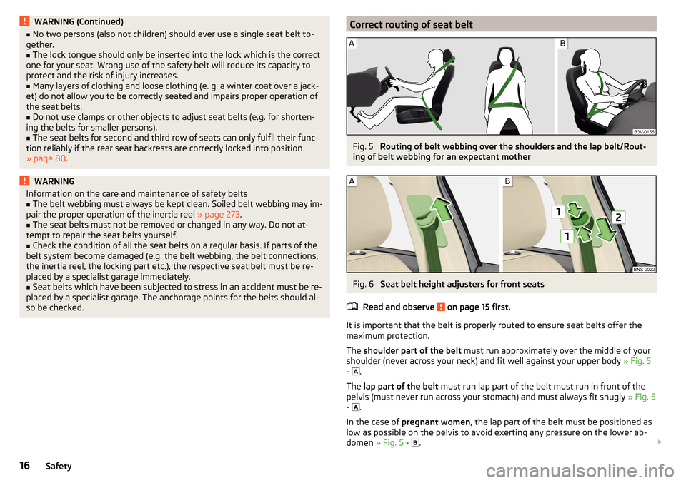
Correct routing of seat beltFig. 5
Routing of belt webbing over the shoulders and the lap belt/Rout-
ing of belt webbing for an expectant mother
Fig. 6
Seat belt height adjusters for front seats
Read and observe
on page 15 first.
It is important that the belt is properly routed to ensure seat belts offer the
maximum protection.
The shoulder part of the belt must run approximately over the middle of your
shoulder (never across your neck) and fit well against your upper body » Fig. 5
-
.
The lap part of the belt must run lap part of the belt must run in front of the
pelvis (must never run across your stomach) and must always fit snugly » Fig. 5
-
.
In the case of pregnant women , the lap part of the belt must be positioned as
low as possible on the pelvis to avoid exerting any pressure on the lower ab-
domen » Fig. 5 -
.
16Safety
Page 22 of 344
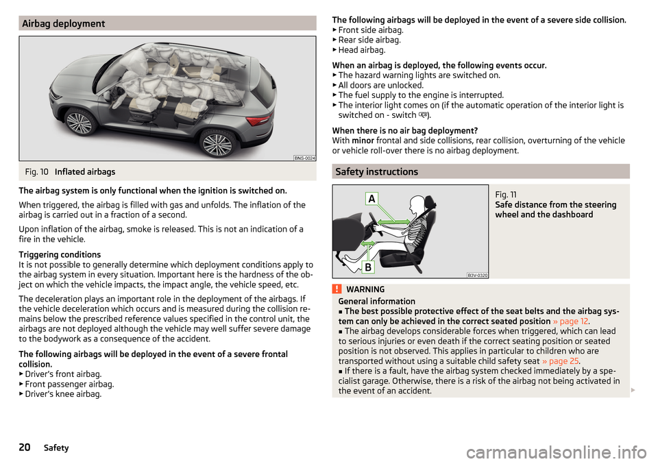
Airbag deploymentFig. 10
Inflated airbags
The airbag system is only functional when the ignition is switched on.
When triggered, the airbag is filled with gas and unfolds. The inflation of the
airbag is carried out in a fraction of a second.
Upon inflation of the airbag, smoke is released. This is not an indication of a fire in the vehicle.
Triggering conditions
It is not possible to generally determine which deployment conditions apply to
the airbag system in every situation. Important here is the hardness of the ob-
ject on which the vehicle impacts, the impact angle, the vehicle speed, etc.
The deceleration plays an important role in the deployment of the airbags. If
the vehicle deceleration which occurs and is measured during the collision re-
mains below the prescribed reference values specified in the control unit, the
airbags are not deployed although the vehicle may well suffer severe damage
to the bodywork as a consequence of the accident.
The following airbags will be deployed in the event of a severe frontal
collision.
▶ Driver’s front airbag.
▶ Front passenger airbag.
▶ Driver’s knee airbag.
The following airbags will be deployed in the event of a severe side collision.
▶ Front side airbag.
▶ Rear side airbag.
▶ Head airbag.
When an airbag is deployed, the following events occur. ▶ The hazard warning lights are switched on.
▶ All doors are unlocked.
▶ The fuel supply to the engine is interrupted.
▶ The interior light comes on (if the automatic operation of the interior light is
switched on - switch
).
When there is no air bag deployment?
With minor frontal and side collisions, rear collision, overturning of the vehicle
or vehicle roll-over there is no airbag deployment.
Safety instructions
Fig. 11
Safe distance from the steering
wheel and the dashboard
WARNINGGeneral information■The best possible protective effect of the seat belts and the airbag sys-
tem can only be achieved in the correct seated position » page 12 .■
The airbag develops considerable forces when triggered, which can lead
to serious injuries or even death if the correct seating position or seated
position is not observed. This applies in particular to children who are
transported without using a suitable child safety seat » page 25.
■
If there is a fault, have the airbag system checked immediately by a spe-
cialist garage. Otherwise, there is a risk of the airbag not being activated in
the event of an accident.
20Safety
Page 29 of 344
Fastening systems
Introduction
This chapter contains information on the following subjects:
attachment points of the
system
27
Use of child safety seats with the
system
27
Using child seats with the
system
28
Attachment points of the
system
28
Recommended child seats
29
attachment points of the system
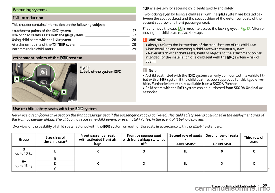
Fig. 17
Labels of the system
is a system for securing child seats quickly and safely.
Two locking eyes for fixing a child seat with the
system are located be-
tween the seat backrest and the seat cushion of the outer rear seats of the
second seat row and front passenger seat.
First, remove the caps A
in order to access the locking eyes » Fig. 17. After re-
moving the child seat, replace he caps.
WARNING■ Always refer to the instructions of the manufacturer of the child seat
when installing and removing a child seat with the system.■
Never attach other child seats, belts or objects to the attachment points
intended for the installation of a child seat with the
system – risk of
death!
Note
■ A child seat fitted with the system can only be mounted in a vehicle fit-
ted with a system if the child seat has been approved for this type of ve-
hicle. Further information is available from a ŠKODA Partner.■
Child seats with the
system can be purchased from ŠKODA Original Ac-
cessories.
Use of child safety seats with the system
Never use a rear-facing child seat on the front passenger seat if the passenger airbag is activated. This child safety seat is positioned in the deployment area of
the front passenger airbag. The airbag may cause the child severe, or even fatal injuries, in the event of it being deployed.Overview of the usability of child seats fastened with the system on each of the seats in accordance with the ECE-R 16 standard.GroupSize class of
the child seat a)Front passenger seat
with activated front air bagb)Front passenger seat
with front airbag switched offb)Second row of seats
-
outer seats c)Second row of seats
-
center seatThird row of seats0
up to 10 kgEXXILXX0+
up to 13 kgE
XXILXX
DC 27Transporting children safely
Page 31 of 344
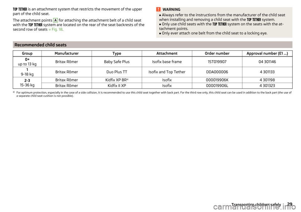
is an attachment system that restricts the movement of the upper
part of the child seat.
The attachment points A
for attaching the attachment belt of a child seat
with the
system are located on the rear of the seat backrests of the
second row of seats » Fig. 18.
WARNING■
Always refer to the instructions from the manufacturer of the child seat
when installing and removing a child seat with the system.■
Only use child seats with the
system on the seats with the at-
tachment points.
■
Only ever attach one belt from the child seat to a locking eye.
Recommended child seatsGroupManufacturerTypeAttachmentOrder numberApproval number (E1 ...)0+
up to 13 kgBritax RömerBaby Safe PlusIsofix base frame1ST01990704 3011461
9-18 kgBritax RömerDuo Plus TTIsofix and Top TetherDDA0000064 3011332-3
15-36 kgBritax RömerKidfix XP BR a)Isofix000019906K4 301198Britax RömerKidfix II XPIsofix000019906L4 301323a)
For optimum protection, especially in the case of a side collision, it is recommended to use this child seat together with back part. For the third row only, this child seat can be used in addition to the back part (the use of
a separate child seat cushion is not possible).
29Transporting children safely
Page 54 of 344
Unlocking and opening
Unlocking and locking
Introduction
This chapter contains information on the following subjects:
Unlocking/locking with the remote control key
52
Remove KESSY emergency key
53
Locking / unlocking - KESSY
53
Locking/unlocking the vehicle with the central locking button
54
SafeLock
54
Individual settings
54
Opening / closing door
55
Door edge protection
55
Child safety lock
56
Malfunctions
57
The vehicle is equipped with a central locking system which makes it possible
to unlock / lock all the doors, the fuel filler flap and boot lid simultaneously.
The door unlocking can be adjusted individually » page 54.
The unlocking of the vehicle is displayed by the turn signal lights flashing
twice.
If you unlock the vehicle and do not open a door or the boot lid within the next
45 seconds, the vehicle will lock again automatically.
The locking of the vehicle is displayed by the turn signal lights flashing once.
If the driver's door has been opened, the vehicle cannot be locked.
If the doors or the boot lid remain open after the vehicle has been locked, the turn signal lights do not flash until they have been closed.
WARNING■ Never leave the key in the vehicle when you exit the vehicle. Unauthor-
ized persons (e.g. children) could lock the car, turn on the ignition or start
the engine - there is a danger of injury and accidents!■
When leaving the vehicle, never leave people who are not completely in-
dependent, such as children, unattended in the vehicle. These individuals
might not be able to leave the vehicle on their own or to help themselves.
Can be fatal at very high or very low temperatures!
CAUTION
■ Each key contains electronic components; therefore it must be protected
against moisture and severe shocks.■
Keep the keyway clean. Impurities (textile fibres, dust etc.) have a negative
effect on the functionality of the locking cylinder and ignition lock.
Unlocking/locking with the remote control key
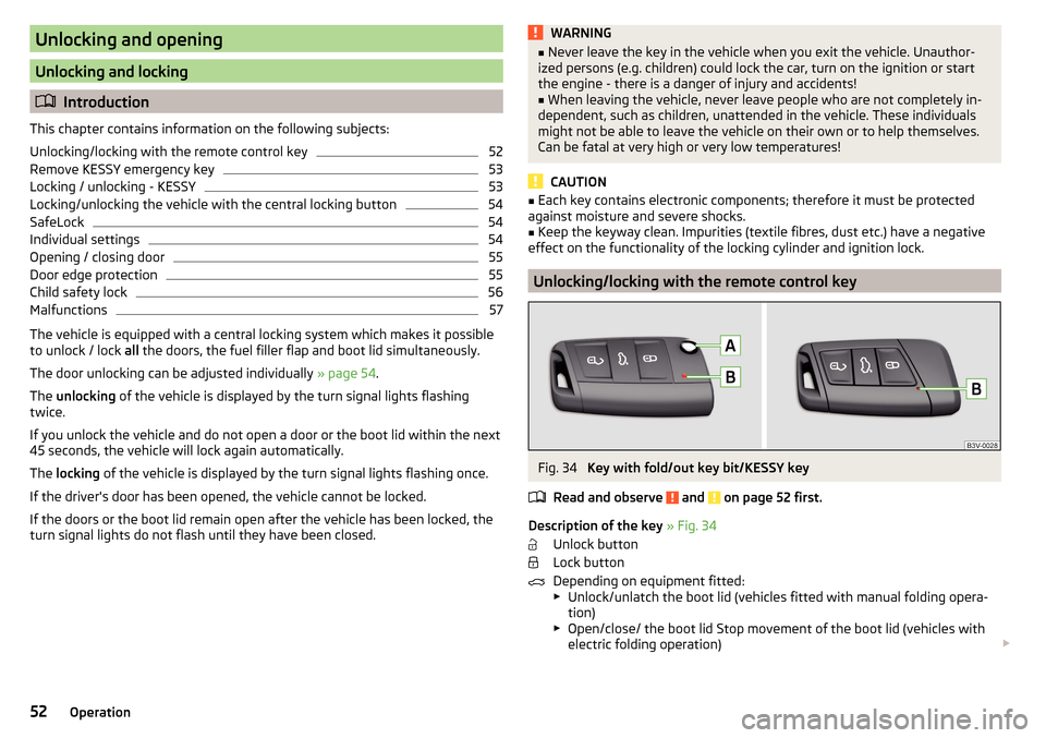
Fig. 34
Key with fold/out key bit/KESSY key
Read and observe
and on page 52 first.
Description of the key » Fig. 34
Unlock button
Lock button
Depending on equipment fitted:
▶ Unlock/unlatch the boot lid (vehicles fitted with manual folding opera-
tion)
▶ Open/close/ the boot lid Stop movement of the boot lid (vehicles with
electric folding operation)
52Operation
Page 55 of 344
Locking button for folding the key bit in/out
Warning light for the battery charge - if the warning light does not flash
when a button on the key is pressed, the battery is discharged.
Unlock/unlatch the boot lid (vehicles fitted with manual folding operation)
By pressing the button
, the lid is unlocked.
By holding the button
, the lid is unlocked and unlatched (partially open).
If the lid is unlocked or unlatched using the
button, then the lid is automat-
ically locked after closing. The period after which the lid is locked can be set
» page 59 .
CAUTION
■
The remote control may be affected by signal superposition of transmitters
that are in the vicinity of the vehicle.■
The effective area of the remote control key is around 30 m. If the central
locking on the remote control responds from a distance of less than around 3
m, the battery must be replaced » page 300.
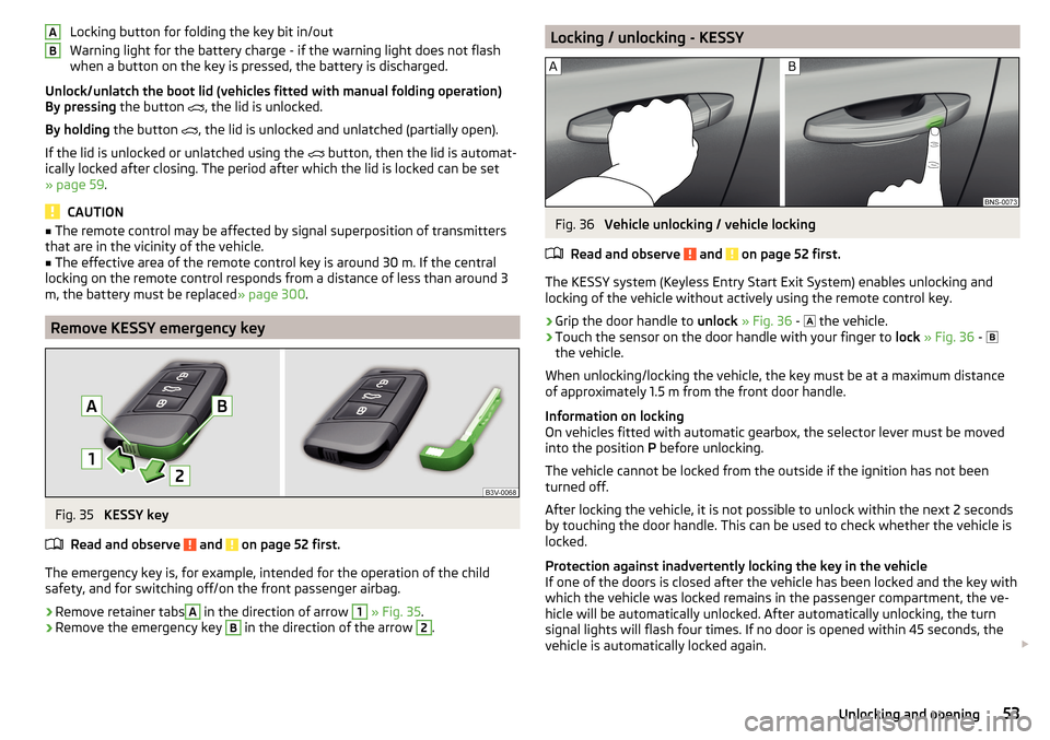
Remove KESSY emergency key
Fig. 35
KESSY key
Read and observe
and on page 52 first.
The emergency key is, for example, intended for the operation of the child
safety, and for switching off/on the front passenger airbag.
›
Remove retainer tabs
A
in the direction of arrow
1
» Fig. 35 .
›
Remove the emergency key
B
in the direction of the arrow
2
.
ABLocking / unlocking - KESSYFig. 36
Vehicle unlocking / vehicle locking
Read and observe
and on page 52 first.
The KESSY system (Keyless Entry Start Exit System) enables unlocking and
locking of the vehicle without actively using the remote control key.
›
Grip the door handle to unlock » Fig. 36 -
the vehicle.
›
Touch the sensor on the door handle with your finger to
lock » Fig. 36 -
the vehicle.
When unlocking/locking the vehicle, the key must be at a maximum distance
of approximately 1.5 m from the front door handle.
Information on locking
On vehicles fitted with automatic gearbox, the selector lever must be moved
into the position P before unlocking.
The vehicle cannot be locked from the outside if the ignition has not been
turned off.
After locking the vehicle, it is not possible to unlock within the next 2 seconds
by touching the door handle. This can be used to check whether the vehicle is
locked.
Protection against inadvertently locking the key in the vehicle
If one of the doors is closed after the vehicle has been locked and the key with
which the vehicle was locked remains in the passenger compartment, the ve-
hicle will be automatically unlocked. After automatically unlocking, the turn
signal lights will flash four times. If no door is opened within 45 seconds, the
vehicle is automatically locked again.
53Unlocking and opening
Page 58 of 344
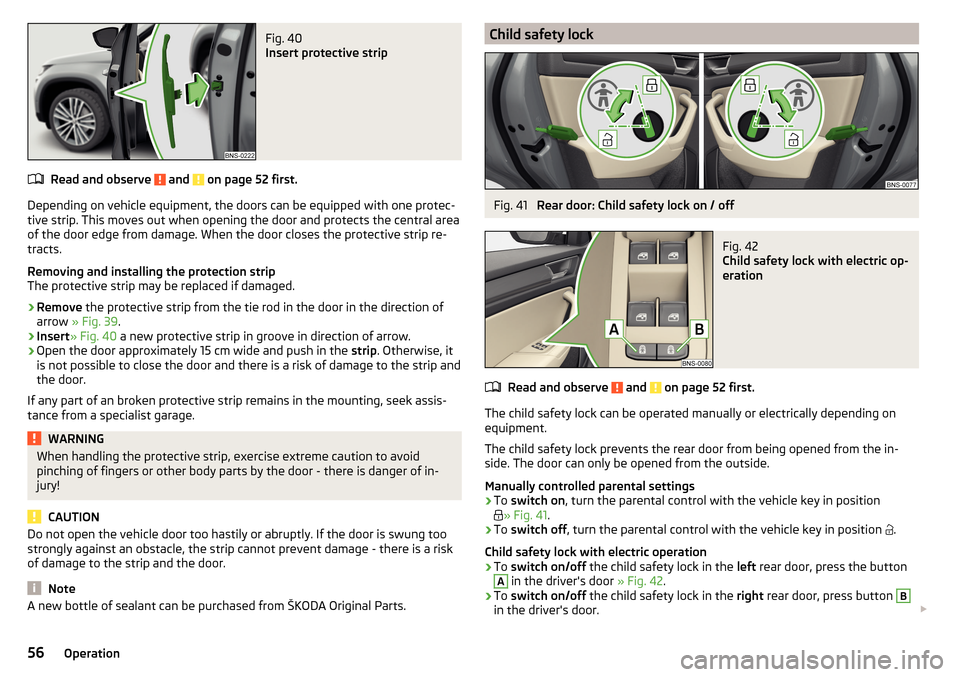
Fig. 40
Insert protective strip
Read and observe and on page 52 first.
Depending on vehicle equipment, the doors can be equipped with one protec-
tive strip. This moves out when opening the door and protects the central area
of the door edge from damage. When the door closes the protective strip re-
tracts.
Removing and installing the protection strip
The protective strip may be replaced if damaged.
›
Remove the protective strip from the tie rod in the door in the direction of
arrow » Fig. 39 .
›
Insert» Fig. 40 a new protective strip in groove in direction of arrow.
›
Open the door approximately 15 cm wide and push in the strip. Otherwise, it
is not possible to close the door and there is a risk of damage to the strip and
the door.
If any part of an broken protective strip remains in the mounting, seek assis-
tance from a specialist garage.
WARNINGWhen handling the protective strip, exercise extreme caution to avoid
pinching of fingers or other body parts by the door - there is danger of in-
jury!
CAUTION
Do not open the vehicle door too hastily or abruptly. If the door is swung too
strongly against an obstacle, the strip cannot prevent damage - there is a risk
of damage to the strip and the door.
Note
A new bottle of sealant can be purchased from ŠKODA Original Parts.Child safety lockFig. 41
Rear door: Child safety lock on / off
Fig. 42
Child safety lock with electric op-
eration
Read and observe and on page 52 first.
The child safety lock can be operated manually or electrically depending on
equipment.
The child safety lock prevents the rear door from being opened from the in-
side. The door can only be opened from the outside.
Manually controlled parental settings
›
To switch on , turn the parental control with the vehicle key in position
» Fig. 41
.
›
To switch off , turn the parental control with the vehicle key in position
.
Child safety lock with electric operation
›
To switch on/off the child safety lock in the left rear door, press the button
A
in the driver's door » Fig. 42.
›
To switch on/off the child safety lock in the right rear door, press button
B
in the driver's door.
56Operation
Page 64 of 344
WARNING■Always close the window carefully and controlled. Otherwise, you may
cause considerable crushing injuries to yourself or fellow passengers.■
The system is fitted with a force limiter » page 63. If there is an obstacle
(e.g. If a body part gets trapped), the closing process is stopped and the
window goes down by several centimetres. However, the windows should
be closed carefully – risk of injury.
CAUTION
■ Keep the windows clean to ensure the correct functionality of the electric
power windows.■
Always close the windows before disconnecting the battery.
Note
If the windows are opened, dust and other dirt can get into the vehicle and the
wind noise is more at certain speeds.
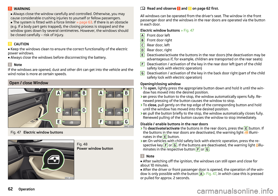
Open / close Window
Fig. 47
Electric window buttons
Fig. 48
Power window button
Read and observe and on page 62 first.
All windows can be operated from the driver's seat. The window in the front
passenger door and the windows in the rear doors are operated via the button
in each door.
Electric window buttons » Fig. 47
Front door left
Front door right
Rear door, left
Rear door, right
Deactivate/activate the buttons in the rear doors (the deactivation may be
advantageous if, for example, children are transported on the rear seats)
Deactivation / activation of the key in the rear door left (part of the child
safety lock with electric operation)
Deactivation / activation of the key in the back door right (part of the child
safety lock with electric operation)
Opening/closing window
›
To open , lightly press the appropriate button down and hold it until the win-
dow has moved into the desired position.
›
or: press the button to the stop, the window automatically opens fully. Re-
newed pressing of the button causes the window to stop.
›
To close , pull gently on the top edge of the corresponding button and hold
until the window has moved into the desired position.
›
or: pull the button briefly to the stop, the window automatically closes fully.
Renewed pulling of the button causes the window to stop immediately.
Disable / enable buttons in the rear doors
›
To deactivate/activate the buttons in the rear doors, press the
E
button. If
the buttons in the rear doors are deactivated, the warning light illumi-
nates in the
E
button.
›
or: On vehicles with child safety lock with electric operation, press the re-
spective key
F
or
G
. If the buttons are deactivated, the warning light illu-
minates in the respective button
F
or
G
.
Note
■ After switching off the ignition, the windows can still open and close for
about 10 minutes.■
After the driver or front passenger door is opened, the operation of the win-
dow is only possible with the button
A
» Fig. 47 , in which case this is pressed
or pulled for approx. 2 seconds.
ABCDEFG62Operation