set clock SKODA OCTAVIA 2006 Owner´s Manual
[x] Cancel search | Manufacturer: SKODA, Model Year: 2006, Model line: OCTAVIA, Model: SKODA OCTAVIA 2006Pages: 218, PDF Size: 5.48 MB
Page 10 of 218
Instruments and warning lights
Instrument cluster
ä
Introduction
This chapter contains information on the following subjects:
Overview 8
Engine revolutions counter 9
Speedometer 9
Coolant temperature gauge 9
Fuel gauge 9
Counter for distance driven 10
Service Interval Display 10
Digital clock 11
Recommended gear 11
WARNING
■ Concentrate fully at all times on your driving! As the driver you are fully re-
sponsible for the operation of your vehicle.
■ Never operate the controls in the instrument cluster while driving, only
when the vehicle is stationary! Ð Overview
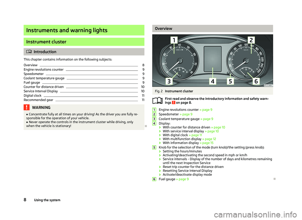
Fig. 2
Instrument cluster
First read and observe the introductory information and safety warn-
ings on page 8.
Engine revolutions counter
» page 9
Speedometer » page 9
Coolant temperature gauge » page 9
Display:
› With counter for distance driven
» page 10
› With service interval display
» page 10
› With digital clock
» page 11
› With multifunction display
» page 12
› With information display » page 15
Knob for the selection of the mode (turn knob)/the setting (press knob):
› Setting the hours/minutes
› Activating/deactivating the second speed in mph or km/h
› Service intervals - Display of the number of days and kilometres remaining
until the next Inspection Service
› Reset trip counter for the distance driven
› Resetting Service Interval Display
› Activate/deactivate display mode
Fuel gauge » page 9 Ð
ä 1
2
3
4
5
6
8
Using the system
Page 13 of 218
The following will be displayed in the information display for 10
seconds:
Service in ... km or ... days.
Resetting Service Interval Display
It is only possible to reset the Service Interval Display, if a service message or at
least a pre-warning is shown in the instrument cluster display.
We recommend that this reset is completed by a
ŠKODA specialist garage.
The ŠKODA specialist garage: › Resets the memory of the display after the appropriate inspection
› Adds an entry to the Service Schedule
› Affixes the sticker with the entry of the following service interval to the side of
the dashboard on the driver's side
Reset the service interval display by using the knob 5
» Fig. 2 on page 8.
On vehicles which are equipped with the information display, you can reset the
Service Interval Display in the menu Settings » page 16.CAUTION
We recommend that you do not reset the Service Interval Display yourself as this
can result in the incorrect setting of the Service Interval Display, which can also
cause possible problems with the operation of your vehicle. Note
■ Never reset the display between service intervals, as this will result in the incor-
rect display. ■ Information is retained in the Service Interval Display even after the vehicle bat-
tery is disconnected.
■ If the instrument cluster is exchanged after a repair, the correct values must be
entered in the counter for the Service Interval Display. This work is carried out by
a ŠKODA specialist garage. ■ After resetting the display with flexible service intervals, the displayed data is
the same as that for a vehicle with fixed service intervals. We therefore recom-
mend that the Service Interval Display is only reset by a
ŠKODA Service Partner,
who will reset the display with a vehicle system tester. ■ For more information on the service intervals » Service Plan. Ð Digital clock
First read and observe the introductory information and safety warn-
ings on page 8.
The clock is set using the knob 5
» Fig. 2 on page 8.
Turn the knob 5
to select the display you wish to change. Make the change by
pressing the knob.
On vehicles that are fitted with the information display, it is also possible to set
the clock in the menu Time » page 16. Ð Recommended gear
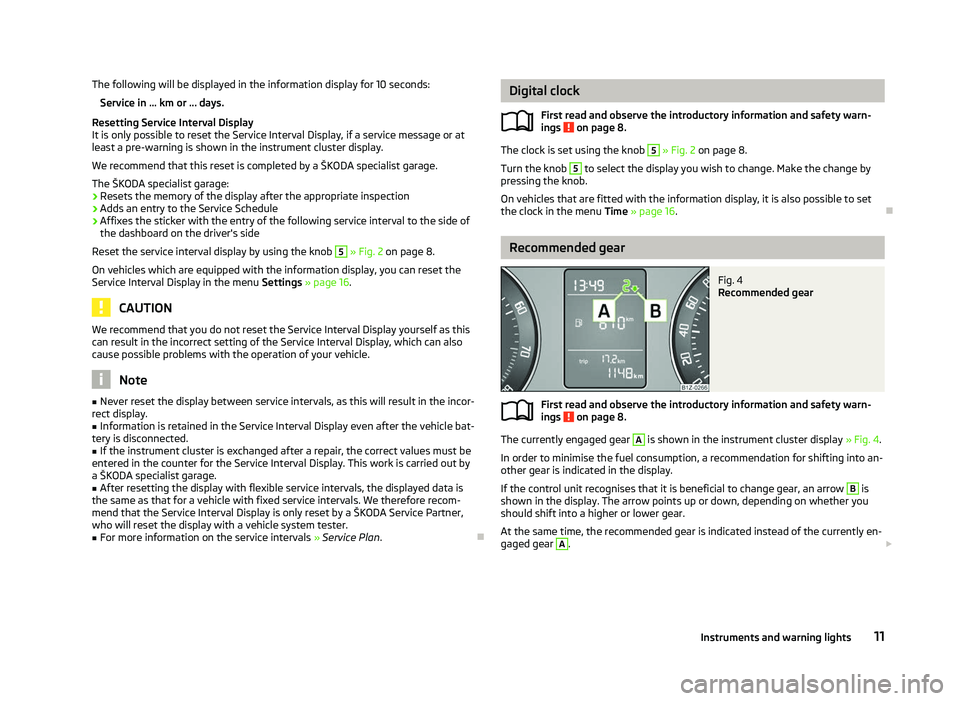
Fig. 4
Recommended gear
First read and observe the introductory information and safety warn-
ings on page 8.
The currently engaged gear A
is shown in the instrument cluster display
» Fig. 4.
In order to minimise the fuel consumption, a recommendation for shifting into an-
other gear is indicated in the display.
If the control unit recognises that it is beneficial to change gear, an arrow B
is
shown in the display. The arrow points up or down, depending on whether you
should shift into a higher or lower gear.
At the same time, the recommended gear is indicated instead of the currently en-
gaged gear A
.
£
ä
ä
11
Instruments and warning lights
Page 124 of 218
What influences the driving safety?
First read and observe the introductory information and safety warn-
ings on page 121.
The driver is fully responsible for himself and his occupants. If your driving safety
is effected, you place yourself and the oncoming traffic at risk.
The following guidelines must therefore be observed. › Do not get distracted from concentrating on the traffic situation, e.g. by your
passengers or mobile phone calls.
› Never drive when your driving ability is impaired, e.g. through medication, alco-
hol, drugs.
› Keep to the traffic regulations and the permissible speed limit.
› Always adjust the driving speed to the road, traffic and weather conditions.
› Take regular breaks on long journeys – at least every two hours. ÐCorrect seated position
ä
Introduction
This chapter contains information on the following subjects:
Correct seated position for the driver 123
Correct seated position for the front passenger 123
Correct seated position for the occupants on the rear seats 123
Examples of an incorrect seated position 124
WARNING
■ The front seats and the head restraints must always be adjusted to match
the body size of the seat occupant as well as the seat belts must always be
correctly fastened in order to provide an optimal protection for you and your
occupants.
■ Always assume the correct seated position before setting off and do not
change this position while driving. Also advise your passengers to adopt the
correct seated position and not to change this position while the car is mov-
ing.
ä WARNING (Continued)
■ If the occupant adopts an incorrect seated position, he is exposed to life-
threatening injuries, in case he is hit by a deployed airbag.
■ If the occupants on the rear seats are not sitting upright, the risk of injury is
increased due to incorrect routing of the seat belt.
■ The driver must maintain a distance of at least 25 cm to the steering wheel.
The front passenger must maintain a distance of at least 25 cm to the dash
panel. Not maintaining this minimum distance will mean that the airbag sys-
tem will not be able to properly protect you - hazard!
■ When driving, hold the steering wheel with both hands firmly on the outer
edge in the 9
o'clock and 3 o'clock position. Never hold the steering wheel in
the 12 o'clock position or in any other way (e.g. in the middle or inner edge of
the steering wheel). In such cases, you could severely injure the arms, hands
and head when the driver airbag is deployed.
■ The seat backrests must not be angled too far back when driving otherwise
this will affect proper operation of the seat belts and of the airbag system -
risk of injury!
■ Ensure that there are no objects in the driver's footwell as they may get
caught behind the pedals when driving or applying the braking. You would
then no longer be able to operate the clutch, brake or accelerate.
■ Always keep your feet in the footwell when the car is being driven - never
place your feet on the instrument panel, out of the window or on the surfaces
of the seats. You will be exposed to increased risk of injury if it becomes nec-
essary to apply the brake or in the event of an accident. If an airbag is de-
ployed, you may suffer fatal injuries when adopting an incorrect seated posi-
tion! Ð
122 Safety
Page 170 of 218
Charging a vehicle battery
First read and observe the introductory information and safety warn-
ings on page 165.
A properly charged vehicle battery is essential for reliably starting the engine.
›
Switch off the ignition and all of the electrical components.
› Only for “quick-charging”: Disconnect both battery cables (first of all “negative”,
then “positive”).
› Attach the terminal clamps of the charger to the battery terminals (red =
“posi-
tive
”, black = “negative”).
› Only now plug the mains cable of the charger into the power socket and switch
on the device.
› When charging is completed: Switch off the charger and remove the mains ca-
ble from the power socket.
› Only then disconnect the charger's terminal clamps.
› Reconnect the cables to the battery, if necessary (first of all
“positive”, then
“negative
”).
It is not normally necessary to disconnect the cables of the battery if you re-
charge the vehicle battery using low amperages (as for example from a mini-
charger). Refer to the instructions of the charger manufacturer.
A charging current of 0.1 multiple of the total vehicle battery capacity (or lower)
must be used until full charging is achieved.
It is, however, necessary to disconnect both cables before charging the battery
with high amperages, so-called “ quick-charging”.
“Quick-charging” the vehicle battery is dangerous and requires a special charger
and specialist knowledge. We therefore recommend having the quick charging of
vehicle batteries undertaken by a ŠKODA specialist garage.
The vent plugs of the vehicle battery should not be opened for charging. CAUTION
On vehicles with the START/STOP system, the pole terminal of the charger must
not be connected directly to the negative terminal of the vehicle battery, but only
to the engine earth » page 186, Jump-starting in vehicles with the
START-STOP
system . Ð
ä Disconnecting and reconnecting the vehicle battery
First read and observe the introductory information and safety warn-
ings on page 165.
On disconnecting and reconnecting the vehicle battery the following functions
are initially deactivated or are no longer able to operate fault-free.
Operation Operating measure
Electrical power window (operational faults) » page 37
Enter the radio/navigation system code num-
ber » User manual of the radio
or »
user manual of the navigation
system
Setting the clock » page 11
Data in the multifunction display are deleted. » page 12 Note
We recommend having the vehicle checked by a ŠKODA Service Partner to ensure
the full functionality of all electrical systems. Ð Replacing the vehicle battery
First read and observe the introductory information and safety warn-
ings on page 165.
When replacing a battery, the new vehicle battery must have the same capacity,
voltage, amperage and be the same size. Suitable types of vehicle batteries can
be purchased from a
ŠKODA Service Partner.
We recommend that the battery is replaced by a ŠKODA Service Partner, where
the new vehicle battery will be installed properly and the original battery will be
disposed of in accordance with national regulations. Ð
ä
ä
168 General Maintenance
Page 214 of 218
Seats
folding forward 59
Head restraints 58
Heating 57
Selector lever see selector lever positions 103
Selector lever positions 103
Service display 10
Setting Automatic dimming interior mirror 52
Manual air conditioning system 84
Manual dimming interior mirror 51
Steering wheel 92
Setting temperature Heating 81
Setting the clock 11
Shifting Diving economically 140
Gearshift lever 97
Side airbag 131
Sliding/tilting roof see Electric sliding/tilting roof 37
Snow chains 176
Spare wheel 173
Speedometer 9
START/STOP Function 100
Starting and stopping the engine 91
Starting engine Jump-starting 185
START STOP Jump-starting 186
Steering active support 95
Steering force assistance 92
Steering wheel 92
Storage 70
Storage compartment Lighting 46
Storage compartments 70Sun visors 47
Switching lights on and off 40
T
Taking care of the vehicle Artificial leather 153
Material coverings 153
Materials 153
Natural leather 153
Seat belts 154
Taking care of your vehicle 148
Automatic car wash system 149
Chrome parts 150
Cleaning the wheels 152
Door lock cylinders 151
Headlight lenses 151
High-pressure cleaner 149
Plastic parts 150
Polishing the paintwork 150
Preservation 150
Rubber seals 151
Washing 149
Washing by hand 149
Wash system 149
TCS 96
Warning light 21
Technical data 197
Telephone 109, 112
Through-loading channel 75
Tilting roof see Electric sliding/tilting roof 37
Tiptronic 102
see automatic gearbox 104
Tool 179
TOP TETHER 137
Towing 186
Towing a trailer 145
Towing eye 187
Towing protection monitoring 32
Traction control system TCS 96Trailer 145
Towing a trailer 145
Transport Boot 60
Roof rack system 66
Transporting children safely 135
Two-way radio systems 107
Type plate 197
Tyre repair 182
Tyres see Wheels and tyres 172
U
Underbody protection 152
unlock Central locking system 28
Unlocking Remote control 30
Uphill start assist 95
V
Vehicle battery Automatic load deactivation 169
Charging 168
Checking the electrolyte level 167
Operation in winter 167
Replacing 168
Safety instructions 165
Vehicle condition see Auto Check Control 17
Vehicle data sticker 197
Vehicle dimensions 198
Vehicle key 26
Vehicle tool kit 179
Visors 47
212 Index