width SKODA OCTAVIA 2006 Owner´s Manual
[x] Cancel search | Manufacturer: SKODA, Model Year: 2006, Model line: OCTAVIA, Model: SKODA OCTAVIA 2006Pages: 218, PDF Size: 5.48 MB
Page 46 of 218
Headlight beam adjustment
Fig. 26
Dash panel: Lights and visibility
First read and observe the introductory information and safety warn-
ings on page 39.
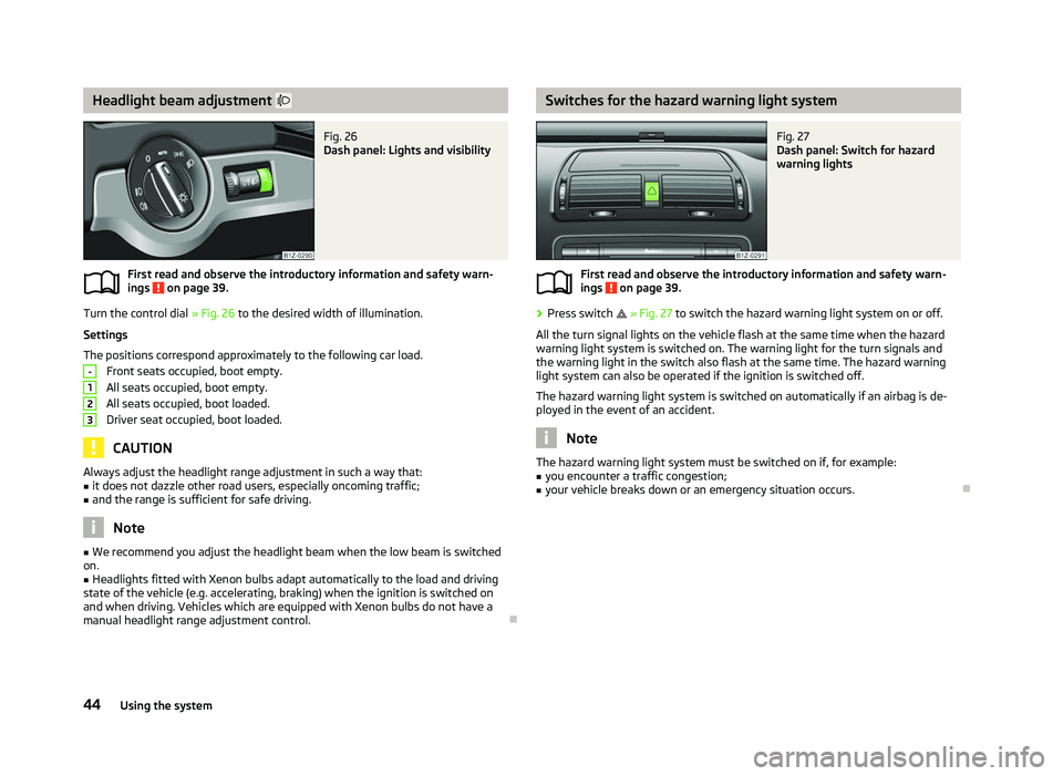
Turn the control dial
» Fig. 26 to the desired width of illumination.
Settings
The positions correspond approximately to the following car load. Front seats occupied, boot empty.
All seats occupied, boot empty.
All seats occupied, boot loaded.
Driver seat occupied, boot loaded. CAUTION
Always adjust the headlight range adjustment in such a way that:
■ it does not dazzle other road users, especially oncoming traffic;
■ and the range is sufficient for safe driving. Note
■ We recommend you adjust the headlight beam when the low beam is switched
on. ■ Headlights fitted with Xenon bulbs adapt automatically to the load and driving
state of the vehicle (e.g. accelerating, braking) when the ignition is switched on
and when driving. Vehicles which are equipped with Xenon bulbs do not have a
manual headlight range adjustment control. Ð
ä -
1
2
3 Switches for the hazard warning light system
Fig. 27
Dash panel: Switch for hazard
warning lights
First read and observe the introductory information and safety warn-
ings on page 39.
›
Press switch
» Fig. 27 to switch the hazard warning light system on or off.
All the turn signal lights on the vehicle flash at the same time when the hazard
warning light system is switched on. The warning light for the turn signals and
the warning light in the switch also flash at the same time. The hazard warning
light system can also be operated if the ignition is switched off.
The hazard warning light system is switched on automatically if an airbag is de-
ployed in the event of an accident. Note
The hazard warning light system must be switched on if, for example:
■ you encounter a traffic congestion;
■ your vehicle breaks down or an emergency situation occurs. Ð
ä
44 Using the system
Page 60 of 218
Head restraints
ä
Introduction
This chapter contains information on the following subjects:
Adjusting, removing and installing a head restraint 58
Middle rear head restraint 58
Best protection is achieved if the top edge of the head restraint is at the same
level as the upper part of your head.
The position of the front and rear outer head restraints is adjustable in height.
The middle rear head restraint is adjustable in two positions.
The head restraints must be adjusted to match the size of the seat occupant. Cor-
rectly adjusted head restraints together with the seat belts offer effective protec-
tion for the occupants » page 122, Correct seated position .WARNING
■ The head restraints must be correctly adjusted in order to offer effective
protection for the occupants in the event of an accident. ■ Never drive with the head restraints removed - risk of injury.
■ If the rear seats are occupied, the rear head restraint must not be in the
lower position. ÐAdjusting, removing and installing a head restraint
Fig. 44
Head restraint: adjusting/removing First read and observe the introductory information and safety warn-
ings on page 58.
Adjusting the height of a head restraint
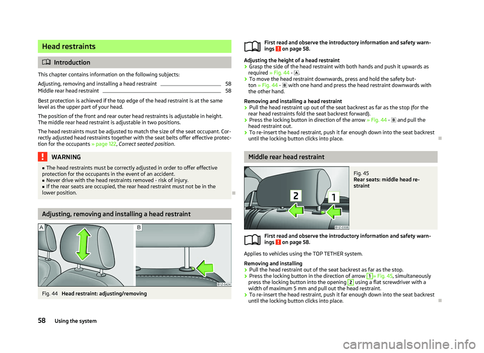
› Grasp the side of the head restraint with both hands and push it upwards as
required » Fig. 44 - .
› To move the head restraint downwards, press and hold the safety but-
ton » Fig. 44 - with one hand and press the head restraint downwards with
the other hand.
Removing and installing a head restraint
› Pull the head restraint up out of the seat backrest as far as the stop (for the
rear head restraints fold the seat backrest forward).
› Press the locking button in direction of the arrow
» Fig. 44 - and pull the
head restraint out.
› To re-insert the head restraint, push it far enough down into the seat backrest
until the locking button clicks into place. Ð Middle rear head restraint
Fig. 45
Rear seats: middle head re-
straint
First read and observe the introductory information and safety warn-
ings on page 58.
Applies to vehicles using the TOP TETHER system.
Removing and installing
› Pull the head restraint out of the seat backrest as far as the stop.
› Press the locking button in the direction of arrow 1
» Fig. 45
, simultaneously
press the locking button into the opening 2
using a flat screwdriver with a
width of maximum 5 mm and pull out the head restraint.
› To re-insert the head restraint, push it far enough down into the seat backrest
until the locking button clicks into place. Ð
ä
ä
58 Using the system
Page 174 of 218
Handling wheels and tyres
Fig. 141
Changing wheels around
First read and observe the introductory information and safety warn-
ings on page 170.
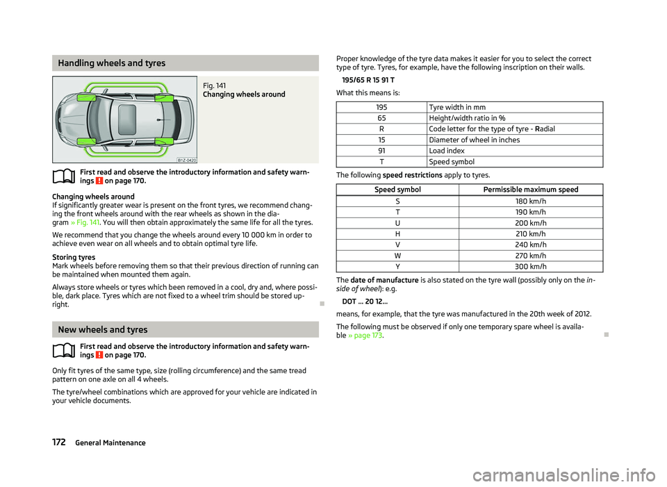
Changing wheels around
If significantly greater wear is present on the front tyres, we recommend chang-
ing the front wheels around with the rear wheels as shown in the dia-
gram » Fig. 141. You will then obtain approximately the same life for all the tyres.
We recommend that you change the wheels around every 10
000 km in order to
achieve even wear on all wheels and to obtain optimal tyre life.
Storing tyres
Mark wheels before removing them so that their previous direction of running can
be maintained when mounted them again.
Always store wheels or tyres which been removed in a cool, dry and, where possi-
ble, dark place. Tyres which are not fixed to a wheel trim should be stored up-
right. ÐNew wheels and tyres
First read and observe the introductory information and safety warn-
ings on page 170.
Only fit tyres of the same type, size (rolling circumference) and the same tread
pattern on one axle on all 4
wheels.
The tyre/wheel combinations which are approved for your vehicle are indicated in
your vehicle documents.
ä
ä Proper knowledge of the tyre data makes it easier for you to select the correct
type of tyre. Tyres, for example, have the following inscription on their walls.
195/65 R
15 91 T
What this means is:
195 Tyre width in mm
65 Height/width ratio in %
R Code letter for the type of tyre - Radial
15 Diameter of wheel in inches
91 Load index
T Speed symbol The following speed restrictions apply to tyres.
Speed symbol Permissible maximum speed
S 180 km/h
T 190 km/h
U 200 km/h
H 210 km/h
V 240 km/h
W 270 km/h
Y 300 km/h The date of manufacture
is also stated on the tyre wall (possibly only on the in-
side of wheel ): e.g.
DOT ... 20 12...
means, for example, that the tyre was manufactured in the 20th week of 2012.
The following must be observed if only one temporary spare wheel is availa-
ble » page 173 . Ð
172 General Maintenance
Page 178 of 218
Wheel bolts
First read and observe the introductory information and safety warn-
ings on page 170.
Wheels and
wheel bolts are matched to each other in terms of design. Each time
you fit other wheels, e.g. light alloy wheels or wheels with winter tyres, you must
therefore also use the matching wheel bolts of the correct length and shape of
spherical cap. This is essential to ensure that the wheels are tightly fitted and
that the brake system operates properly. ÐWinter tyres
First read and observe the introductory information and safety warn-
ings on page 170.
The handling of your vehicle will be significantly improved when driving on wintry
roads if you fit winter tyres. Summer tyres do not offer the same grip on ice, snow
and at temperatures below 7 °C because of their construction (width, rubber
blend, tread pattern). This particularly applies to vehicles which are equipped with
low-profile tyres
or high-speed tyres (code index H or V on wall of tyre).
To achieve the best possible handling properties, winter tyres must be fitted on
all 4 wheels, the minimum tread depth must be 4
mm and tyres must be no older
than 4 years.
Winter tyres of a lower speed category can be used provided that the permissible
maximum speed of these tyres is not exceeded even if the possible maximum
speed of the vehicle is higher. For the sake of the environment
Fit the summer tyres on again in good time as they provide better handling prop-
erties, a shorter braking distance, less tyre noise, and reduced tyre wear on roads
which are free of snow and ice as well as at temperatures above 7
°C. The fuel
consumption is also lower. ÐSnow chains
First read and observe the introductory information and safety warn-
ings on page 170.ä
ä
ä Snow chains must only be mounted on the front wheels.
When driving on wintry roads, snow chains improve not only traction, but also the
braking performance.
For technical reasons, it is only permissible to fit snow chains with the following
wheel/tyre combinations.
Wheel size Depth (D)Tyre size
6J x 15 a)
47 mm 195/65
6.5J x 15 a)
50 mm 195/65
6J x 16 a)
50 mm 205/55
6J x 17 b)
45 mm 205/50 a)
Only fit snow chains with links and locks not larger than 15 mm.
b) Only fit snow chains with links and locks not larger than 9 mm.
Remove the full wheel trims before installing the snow chains.
Observe the national legal regulations relating to the use of snow chains and the
maximum vehicle speed with snow chains. CAUTION
The chains must be removed when driving on roads which are free of snow. They
adversely affect the handling of your vehicle, damage the tyres and are rapidly
destroyed. Ð176
General Maintenance
Page 200 of 218
Measuring the fuel consumption and CO
2 emissions according to the ECE
standards and EU guidelines
The measurement of the intra-urban cycle begins with a cold start of the engine.
Afterwards urban driving is simulated.
In the extra-urban driving cycle, the vehicle is accelerated and decelerated in all
gears, corresponding to daily routine driving conditions. The driving speed varies
between 0 and 120 km/h.
The calculation of the combined fuel consumption considers a weighting of about
37 % for the intra-urban cycle and 63 % for the extra-urban cycle. WARNING
Do not exceed the specified maximum permissible weights - risk of accident
and damage. Note
■ If required, you can find out the precise weight of your vehicle by contacting a
ŠKODA
Service Partner.
■ Depending on the range of equipment, style of driving, traffic situation, weather
influences and vehicle condition, consumption values may deviate from the indi-
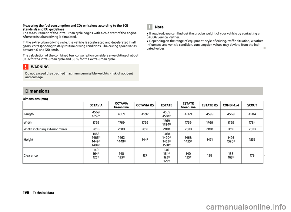
cated values. ÐDimensions
Dimensions (mm) OCTAVIAOCTAVIA
GreenLine OCTAVIA RS ESTATE ESTATE
GreenLine ESTATE RS COMBI 4x4 SCOUT
Length 4569
4597 a)
4569
45974569
4584 b)
4569 4599 4569 4584
Width 1769176917691769
1784 b)
1769 1769 1769 1784
Width including exterior mirror 201820182018 2018 2018 2018 2018 2018
Height 1462
1485 c)
1449 d)
1484 a) 1462
1449 d)
1447 1468
1490 c)
1455 d)
1501 b) 1468
1455 d)
1451 1495
1520 c)
1533
Clearance 140
164 c)
125 d) 140
125 d)
127 140
164 c)
125 d)
179 b) 140
125 d)
128 138
163 c)
179
£198
Technical data