park assist SKODA OCTAVIA 2007 1.G / (1U) User Guide
[x] Cancel search | Manufacturer: SKODA, Model Year: 2007, Model line: OCTAVIA, Model: SKODA OCTAVIA 2007 1.G / (1U)Pages: 288, PDF Size: 15.19 MB
Page 134 of 288
Automatic gearbox DSG133
Using the systemSafetyDriving TipsGeneral MaintenanceBreakdown assistanceTechnical Data
•If you are stopping at a hill (downhill section), never try to hold the car
stationary with the gear engaged by me ans of the “accelerator”, this means
by letting the clutch slip. This can lead to overheating of the clutch. If there is
a risk of overheating of the clutch due to overload, the clutch is opened auto-
matically and the vehicle rolls backward - risk of accident!
•If you must stop at a slope, depress and hold the brake pedal, so that you
can prevent the vehicle from rolling back.
Caution
•The double clutch on the automatic gear box DSG is equipped with an overload
protection. If you make use of the uphill f unction on a vehicle which is stationary or
driving slowly uphill, it will result in an increase of thermal stress of the clutches.
•An overheating of the clutches can be detected by the flashing of the selector
level indicator and the “jerk” of the clut ches, finally the clutches are opened. The
power transmission from the engine to the front wheels is interrupted and as a
result of this the vehicle ca n no longer be driven. If the clutch opens automatically,
depress the brake pedal, wait a few seconds and only then continue driving.
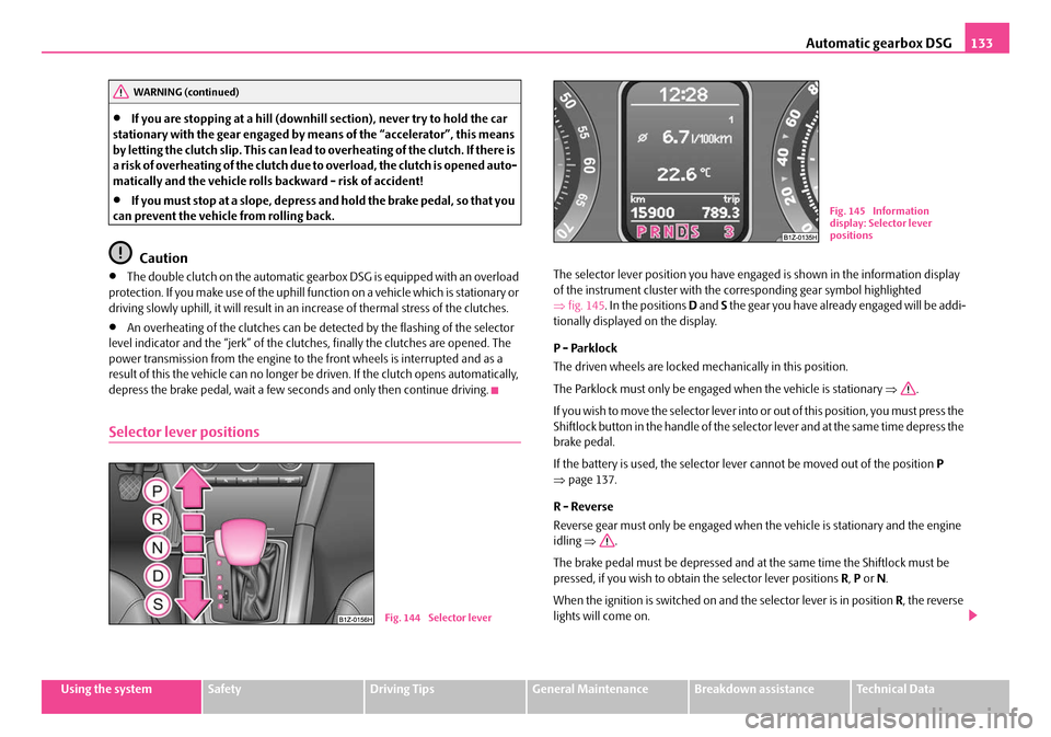
Selector lever positions
The selector lever position you have engaged is shown in the information display
of the instrument cluster with the co rresponding gear symbol highlighted
⇒ fig. 145 . In the positions D and S the gear you have already engaged will be addi-
tionally displayed on the display.
P - Parklock
The driven wheels are locked me chanically in this position.
The Parklock must only be engage d when the vehicle is stationary ⇒.
If you wish to move the select or lever into or out of this position, you must press the
Shiftlock button in the handle of the select or lever and at the same time depress the
brake pedal.
If the battery is used, the selector le ver cannot be moved out of the position P
⇒ page 137.
R - Reverse
Reverse gear must only be engaged when the vehicle is stationary and the engine
idling ⇒ .
The brake pedal must be depressed and at the same time the Shiftlock must be
pressed, if you wish to obtain the selector lever positions R, P or N.
When the ignition is switched on and the selector lever is in position R, the reverse
lights will come on.
WARNING (continued)
Fig. 144 Selector lever
Fig. 145 Information
display: Selector lever
positions
NKO A5 20 MR08.book Page 133 Wednesday, April 11, 2007 2:54 PM
Page 189 of 288

Intelligent Technology
188
Diesel particle filter* (diesel engine)
In the diesel particle filter the resulting soot particles are collected
and burnt during the combustion of diesel fuel.
Code 7GG on the vehicle data sticker ⇒fig. 187 indicates that your
vehicle is equipped with a diesel particle filter. The vehicle data sticker is
located on the floor of the luggage compartment and is also stated in the
Service schedule.
The diesel particle filter filters the soot particles completely from the exhaust. The
soot is collected in the diesel particle filter and burnt regularly. To assist this proce-
dure, we recommend not to drive regularly over short distances.
If the diesel particle filter is clogged or there is a fault, it is indicated by the warning
light
⇒ page 26, “Diesel particle filter* (diesel engine)”.
WARNING
•The diesel particle filter achieves very high temperatures. Therefore do
not park at points where the hot filter comes into direct contact with dry
grass or other combustible materials - risk of fire!
•Never use additional underbody protection or corrosion-protection
agents for the exhaust pipes, catalytic converters, diesel particle filter or
heat shields. When the engine reaches its operating temperature, these
substances might ignite - risk of fire.
Note
•When using diesel fuel with high sulphur content the life of the diesel particle
filter is clearly reduced. A specialist garage will be able to tell you which countries
use only diesel fuel wi th high sulphur content.
Fig. 187 Vehicle data
sticker
WARNING (continued)
NKO A5 20 MR08.book Page 188 Wednesday, April 11, 2007 2:54 PM
Page 200 of 288

Taking care of your vehicle and cleaning the vehicle199
Using the systemSafetyDriving TipsGeneral MaintenanceBreakdown assistanceTechnical Data
General Maintenance
Taking care of your vehicle and cleaning the vehicle
General
Proper care retains the value of your vehicle.
Regular and proper care retains the value of your vehicle. It may also be one of the
requirements for the acceptance of warran ty claims relating to corrosion damage
and paint defects on the bodywork.
We recommend using a preservative from Škoda genuine accessories offered by
your Škoda dealer. Please follow the instructions for use on the package.
WARNING
•Care products may be harmful to your health if not used according to the
instructions.
•Always store care products in a safe place, out of the reach of children -
risk of poisoning!
For the sake of the environment
•Always select environmentally-friendly pr oducts when purchasing vehicle care
products.
•Do not dispose of the packages with re sidues of care products in domestic
waste.
Care of the exterior of vehicle
Washing the vehicle
Frequent washing protects your vehicle.
The best protection for your vehicle agai nst harmful environmental influences is
frequent washing and wax treatment. How of ten you should wash your vehicle
depends on a wide range of factors, such as:
•Frequency of use,
•The parking situation (garage, below trees etc.),
•Season of the year,
•Weather conditions,
•Environmental influences.
The longer insect residues, bird droppings, tree sap, road and industrial dust, tar,
soot particles, road salt and other aggressive deposits remain adhering to the paint-
work of your vehicle, the more detrimental their destructive effect can be. High
temperatures, such as those caused by in tensive sun's rays, accentuate this caustic
effect.
It may therefore be necessary, in certain circumstances, to wash the car once a
week . It may also be sufficient, however, to wash the car once a month followed
by appropriate wax treatment.
It is essential to also thoroughly wash the underside of your vehicle at the end of
the winter road salting and gritting period.
WARNING
When washing your vehicle in the wint er: Water and ice in the brake system
can affect the braking efficiency - risk of accident!
NKO A5 20 MR08.book Page 199 Wednesday, April 11, 2007 2:54 PM
Page 206 of 288

Taking care of your vehicle and cleaning the vehicle205
Using the systemSafetyDriving TipsGeneral MaintenanceBreakdown assistanceTechnical Data
Removing stains
– Remove fresh stains which are water-based (e.g. coffee, tea, juices,
blood etc.) with an absorbent cloth or household paper or use the
cleaner from the care set for a stain which has already dried in.
– Remove fresh stains on a fat base (e.g. butter, mayonnaise, chocolate
etc.) with an absorbent cloth or household cleaning paper or with the
cleaner from the care set if the stain has not yet penetrated into the
surface.
– Use a grease dissolver for grease stains which have dried in .
–Eliminate special stains (e.g. ball-point pens, felt pen, nail varnish,
dispersion paint, shoe cream etc.) with a special stain remover suit-
able for leather.
Leather care
– Treat the leather every six months with the leather care product avail- able from Škoda Service Partners.
– Apply only a small amount of the care product.
– Dry the leather off with a soft cloth
It is best to consult your Škoda Service Partner if you have any questions regarding
cleaning and care of the leather interior.
Caution
•You must on no account treat the leathe r with solvents (e.g. gasoline, turpen-
tine), floor wax, shoe cream or such like.
•Avoid leaving your vehicle for lengthy pe riods in bright sunlight in order to
avoid bleaching the leather. If you leave your vehicle parked in the open for lengthy
periods, protect the leather from the direct rays of the sun by covering it over.
•Sharp-edged objects on items of clothing such as zip fasteners, rivets, sharp-
edged belts may leave permanent scratche s or signs of rubbing on the surface.
Note
•Use a care cream with light blocker and impregnation effect regularly and each
time after cleaning the leather. The cream no urishes the leather, allows it to breathe
and keeps it supple and also provides moisture. It also creates surface protection.
•Clean the leather every 2 to 3 months, remove fresh soiling each time this
occurs.
•Remove fresh stains such as those from ball-point pens, ink, lipstick, shoe
cream etc., as quickly as possible.
•Care also for the leather dye. Refreshen areas which have lost their colour with
a special coloured leather cream as required.
Seat belts
– Keep the seat belts clean!
– Wash seat belts which have become soiled using a mild soapy solu-
tion.
– Inspect the seat belts regularly to ensure they are in good condition.
Belt webbing which has become severely so iled may prevent the inertia reel from
reeling up the belt properly.
WARNING
•The seat belts must not be removed for cleaning.
•Never clean the seat belts chemically as dry cleaning may destroy the
fabric. The seat belts must also not be allowed to come into contact with
corrosive liquids (such as acids etc.).
•Seat belts which have damage to the webbing, the connections, the
inertia reel or the lock should be replaced by a Škoda Service Partner.
•Inertia reel belts must be completely dried before being reeled up.
NKO A5 20 MR08.book Page 205 Wednesday, April 11, 2007 2:54 PM
Page 214 of 288

Inspecting and Replenishing213
Using the systemSafetyDriving TipsGeneral MaintenanceBreakdown assistanceTechnical Data
Check engine oil level
The dipstick indicates the level of oil in the engine.
Checking the oil level
– Park the vehicle on a horizontal surface.
– Switch the engine off.
– Open the bonnet ⇒ in “Working in the engine compartment” on
page 210.
– Wait a few minutes and pull out the oil dipstick.
– Wipe off the dipstick with a clea n cloth and insert it again fully.
– Then withdraw the dipstick ag ain and read off the oil level.
Oil level within range
– You must not top up the oil.
Oil level within range
– You may top up the oil. It is possible that the oil level may then be
within range after doing this. Oil level within range
–You
must top up the oil ⇒page 213. It is sufficient, once this is done,
to keep the oil level is within range .
It is normal for the engine to consume oil. The oil consumption may be as much as
0.5 l/1 000 km depending on your style of driving and the conditions under which
you operate your vehicle. The oil consumpt ion may be slightly higher than this
during the first 5 000 kilometres.
One should therefore check the oil level at regular intervals, preferably every time
after the fuel tank is filled or after driving for long stretches.
We recommend maintaining the oil level within the range if the engine has been
operating at high loads, for example during a lengthy motorway trip during the
summer months, towing a trailer or negotiating a high mountain pass, but not
above this .
The warning light in the instrument cluster* will indicate ⇒page 30, “Engine oil
level* ” whether the oil level is too low. In this case, check the oil level as soon as
possible. Top up with an a ppropriate quantity of oil.
Caution
•The oil level must on no account ex tend beyond the range . Danger of
damaging the catalytic converter.
•Do not continue your journey if for some reason it is not possible under the
conditions prev ailing to top up with oil. Switch of the engine and contact and
obtain professional assistance from a specialist garage.
Replenishing engine oil
– Inspecting the engine oil level ⇒page 213.
– Unscrew the cap of the engine oil filler opening.
– Pour in a suitable grade of oil in portions of 0.5 litres ⇒page 212,
“Engine oil specifications”.
Fig. 198 Dipstick
Aa
Ab
Aa
Ac
Ab
Aa
Aa
NKO A5 20 MR08.book Page 213 Wednesday, April 11, 2007 2:54 PM
Page 234 of 288
Breakdown assistance233
Using the systemSafetyDriving TipsGeneral MaintenanceBreakdown assistanceTechnical Data
The tyre repair kit is located in a textile ba
g. There is a velcro fastener on the under-
side of the bag, with which the bag is atta ched to the floor covering of the luggage
compartment in such a way that the side of the bag rests on the right side of the
luggage compartment and on the seat backrest.
Spare wheel
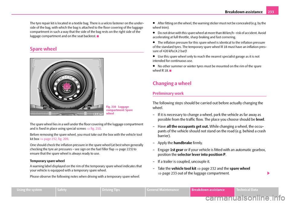
The spare wheel lies in a well under the floor covering of the luggage compartment
and is fixed in place using special screws ⇒fig. 210 .
Before removing the spare wheel, you must take out the box with the vehicle tool
kit box ⇒page 232, fig. 209 .
One should check the inflation pressure in the spare wheel (at best when generally
checking the tyre air pressures - see sign on the fuel filler flap ⇒page 223) to
ensure that the spare wheel is always ready to use.
Temporary spare wheel
A warning label displayed on the rim of the temporary spare wheel indicates that
your vehicle is equipped with a temporary spare wheel.
Please observe the following notes when driving with a temporary spare wheel:
•After fitting on the wheel, the warning st icker must not be concealed (e.g. by the
wheel trim).
•D o n o t d r i v e w i t h th i s s p a re w h e e l a t m o re th a n 8 0 k m / h - ri s k o f a c c i d e n t. Av o i d
accelerating at full throttle, sharp braking and fast cornering.
•The inflation pressure for this spare wheel is identical to the inflation pressure
of the standard tyres. The temporary spar e wheel R 18 must have an inflation pres-
sure of 420 kPa (4.2 bar)!
•Use this spare wheel only to reach the nearest specialist garage as it is not
intended for continuous use.
•No other summer or winter tyres must be mounted on the rim of the spare
wheel R 18.
Changing a wheel
Preliminary work
The following steps should be carried out before actually changing the
wheel.
– If it is necessary to change a wheel, park the vehicle as far away as possible from the traffic flow. The place you choose should be level.
–Have all the occupants get out. While changing a wheel, the occu-
pants of the vehicle should not stan d on the road (e.g. behind a crash
barrier).
– Apply the handbrake firmly.
–Engage 1st gear or if your vehicle is fitted with an automatic gearbox,
position the selector lever into position P.
– If a trailer is coupled, uncouple it.
– Take the vehicle tool kit ⇒ page 232 and the spare wheel
⇒ page 233 out of the luggage compartment.Fig. 210 Luggage
compartment: Spare
wheel
NKO A5 20 MR08.book Page 233 Wednesday, April 11, 2007 2:54 PM
Page 240 of 288

Breakdown assistance239
Using the systemSafetyDriving TipsGeneral MaintenanceBreakdown assistanceTechnical Data
Start engine
It is important to connect the jump -start cables in the correct order.
Connecting positive terminals
– Attach one end to the positive terminal ⇒fig. 217 of the
discharged battery .
– Attach the other end to the positive terminal of the battery supplying the power .
Connecting negative term inal and engine block
– Attach one end to the negative terminal of the battery supplying
the power .
– Attach the other end to a solid metal part which is connected firmly to the engine block, or to the engine block itself.
Starting engine
– Start the engine of the vehicle providing current and run the engine at idling speed.
– Now start the engine of the vehicle with the discharged battery. – Interrupt the attempt at starting an engine after 10 seconds if it does
not start right away and wait for about 30 seconds before repeating
the attempt.
– Disconnect the cables on the engine in exactly the reverse order they
were connected up.
WARNING
•The non-insulated parts of the terminal clamps must never make contact
with each other. Furthermore, the cable connected to the positive terminal
of the battery must not come into contact with electrically conducting parts
of the vehicle - risk of a short circuit!
•Do not affix the jump starting cables to the negative terminal of the
discharged battery. There is the risk of detonating gas seeping out the
battery being ignited by the strong spark which results from the engine
being started.
•Run the jump-start cables so that th ey cannot be caught by any rotating
parts in the engine compartment.
•Do not bend over the batteries - risk of caustic burns!
•The vent screws of the battery cells must be tightened firmly.
•Keep any sources of ignition (naked flame, smouldering cigarettes etc.)
away from the battery - risk of an explosion!
Tow-starting and towing vehicle
General
Please pay attention to the following in structions if you are going to use a
tow rope:
Driver of the towing vehicle
– Do not drive off until the tow rope is taught.
Fig. 217 Jump-starting
using the battery from
another vehicle: A - flat
vehicle battery, B -
battery providing current
A1
AA
A2
AB
A3
AB
A4
NKO A5 20 MR08.book Page 239 Wednesday, April 11, 2007 2:54 PM
Page 248 of 288
Fuses and light bulbs247
Using the systemSafetyDriving TipsGeneral MaintenanceBreakdown assistanceTechnical Data
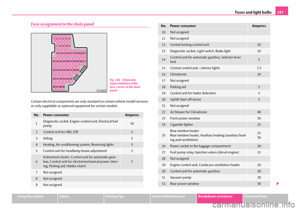
Fuse assignment in the dash panel
Certain electrical components are only standard on certain vehicle model versions
or only suppliable as optional equipment for certain models.
No.Power consumerAmperes
1Diagnostic socket, Engine co ntrol unit, Electrical fuel
pump10
2Control unit for ABS, ESP5
3Airbag5
4Heating, Air conditioning system, Reversing lights5
5Control unit for headla mp beam adjustment5
6Instrument cluster, Contro l unit for automatic gear-
box, Control unit for elec tromechanical power steer-
ing, Parking aid; Haldex clutch5
7Not assigned
8Not assigned
9Not assigned
Fig. 226 Schematic
representation of the
fuse carrier in the dash
panel
10Not assigned
11Not assigned
12Central locking control unit10
13Diagnostic socket, Light switch, Brake light10
14Control unit for automatic gearbox, Selector lever
lock5
15Central control unit - interior lights7,5
16Climatronic10
17Not assigned
18Parking aid5
19Control unit for trailer detection5
20Uphill-Start off-Assist5
21Not assigned
22Air blower for Climatronic40
23Front power window30
24Cigarette lighter25
25Rear window heater
Rear window heater, Auxiliar y heating (auxiliary heat-
ing and ventilation)25
30
26Power socket in the luggage compartment20
27Fuel pump relay, Injection valves (diesel engine)15
28Not assigned
29Engine control unit, Crankcase ventilation heater10
30Control unit for automatic gearbox20
31Vacuum pump20
32Rear power window30
No.Power consumerAmperes
NKO A5 20 MR08.book Page 247 Wednesday, April 11, 2007 2:54 PM
Page 249 of 288

Fuses and light bulbs
248
Electrically adjustable seats are protected by automatic circuit breakers, which
switch on again automatically after a few seconds after the overload has been
eliminated.
Bulbs
Changing bulbs
The relevant lamp must always be switch ed off before a light bulb is replaced. Defect light bulbs should only be replaced
with light bulbs of the same type. The
designation is located on the li ght socket or the glass bulb.
Changing certain bulbs is not something wh ich you can do yourself, but requires to
be done by a specialist. Other parts of the vehicle must be removed in order to
change the light bulbs. This applies, in particular, to bulbs which can only be
reached from the engine compartment.
We therefore recommend that you have any bulbs changed by a Škoda Service
Partner or, in exceptional cases, by ca lling on other professional assistance.
Please note that the engine compartment is a hazardous area ⇒page 210.
We recommend that you carry the set of light bulbs with you which was delivered
in your vehicle. Replacement light bulbs
13) are available at specialist garages.
The set of light bulbs can be stowed in the locable box in the spare wheel.
Fitted with a xenon headlight
Change of light bulbs on Xenon lights (low beam lights, parking lights and main
beam lights) should be undertaken by a specialist garage.
Overview of bulbs
33Electric sliding/tilting roof25
34Control unit for convenience functions20
35Anti-theft alarm system5
36Headlight cleaning system20
37Front seat heating30
38Heated rear seats30
39Not assigned
40Air blower for heating and air conditioning40
41Rear window wiper15
42Wipe wash pump for windscreen15
43Towing device15
44Towing device20
45Towing device15
46Heated windscreen washer nozzles5
47Relay for auxiliary heating5
48Not assigned
49Light switch5
No.Power consumerAmperes
13)Replacement light bulbs are, on the other hand, part of the basic equipping of the vehicle in
some countries.
Front headlightHalogen headlightXenon headlight
Low beamH7D1S
Main beamH1
Parking lightsW5W
Tu r n s i g n a l sPY21W
Fog lightsH8/H1a)
a)Octavia RS
NKO A5 20 MR08.book Page 248 Wednesday, April 11, 2007 2:54 PM
Page 250 of 288
Fuses and light bulbs249
Using the systemSafetyDriving TipsGeneral MaintenanceBreakdown assistanceTechnical Data
WARNING
•Bulbs H7 and H1 are pressurised and may burst when changing the bulb
- risk of injury!
•It is recommended to wear gloves and eye protection when changing a
light bulb.
•Gas discharge bulbs* (xenon bulbs) op erate with a high voltage, profes-
sional knowledge is required - danger to life!
Caution
Do not take hold of the glass bulb with naked fingers (even the smallest amount of
dirt reduces the working life of the light bu lb). Use a clean cloth, serviette or some-
thing similar.
Note
This Owner's Manual only describes the replacement of bulbs where it is assumed
that no major complications wi ll arise. Other light bulbs should be changed by your
specialist garage.
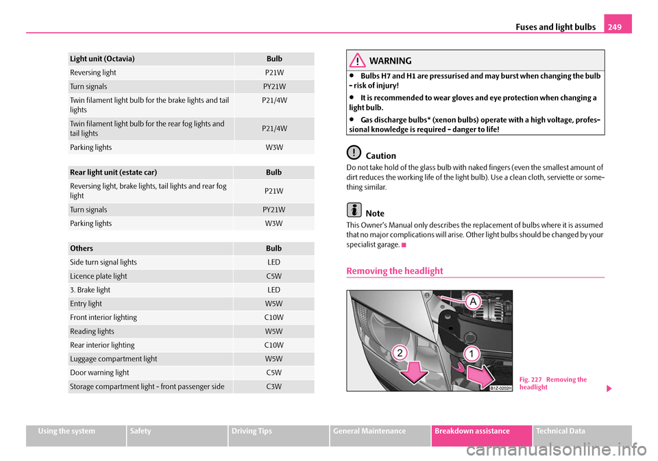
Removing the headlight
Light unit (Octavia)Bulb
Reversing lightP21W
Tu r n s i g n a l sPY21W
Twin filament light bulb for the brake lights and tail
lightsP21/4W
Twin filament light bulb for the rear fog lights and
tail lightsP21/4W
Parking lightsW3W
Rear light unit (estate car)Bulb
Reversing light, brake lights, tail lights and rear fog
lightP21W
Tu r n s i g n a l sPY21W
Parking lightsW3W
OthersBulb
Side turn signal lightsLED
Licence plate lightC5W
3. Brake lightLED
Entry lightW5W
Front interior lightingC10W
Reading lightsW5W
Rear interior lightingC10W
Luggage compartment lightW5W
Door warning lightC5W
Storage compartment light - front passenger sideC3WFig. 227 Removing the
headlight
NKO A5 20 MR08.book Page 249 Wednesday, April 11, 2007 2:54 PM