technical data SKODA OCTAVIA 2007 1.G / (1U) Owner's Manual
[x] Cancel search | Manufacturer: SKODA, Model Year: 2007, Model line: OCTAVIA, Model: SKODA OCTAVIA 2007 1.G / (1U)Pages: 288, PDF Size: 15.19 MB
Page 5 of 288
Contents
4
Important safety information regarding the use of seat
belts . . . . . . . . . . . . . . . . . . . . . . . . . . . . . . . . . . . . . . . . .
How are seat belts correctly fastened? . . . . . . . . . .
Belt tensioners . . . . . . . . . . . . . . . . . . . . . . . . . . . . . . .
Airbag system . . . . . . . . . . . . . . . . . . . . . . . . . . . . . . . . .
Description of the airbag system . . . . . . . . . . . . . . .
Front airbag . . . . . . . . . . . . . . . . . . . . . . . . . . . . . . . . . .
Side airbags* . . . . . . . . . . . . . . . . . . . . . . . . . . . . . . . . .
Head airbags* . . . . . . . . . . . . . . . . . . . . . . . . . . . . . . . .
Deactivating an airbag . . . . . . . . . . . . . . . . . . . . . . . .
Transporting children safely . . . . . . . . . . . . . . . . . .
What you should know about transporting children!
Child seat . . . . . . . . . . . . . . . . . . . . . . . . . . . . . . . . . . . .
Attaching a child seat using the “ISOFIX” system .
Attaching child seat using the “Top Tether” system
Driving Tips. . . . . . . . . . . . . . . . . . . . . . . . . . . . . .
Intelligent Technology . . . . . . . . . . . . . . . . . . . . . . . .
Electronic stability programme (ESP)* . . . . . . . . . .
Brakes . . . . . . . . . . . . . . . . . . . . . . . . . . . . . . . . . . . . . . .
Brake booster . . . . . . . . . . . . . . . . . . . . . . . . . . . . . . . .
Antilock brake system (ABS) . . . . . . . . . . . . . . . . . . .
Brake Assist* . . . . . . . . . . . . . . . . . . . . . . . . . . . . . . . . .
Uphill-Start off-Assist* . . . . . . . . . . . . . . . . . . . . . . . .
Electromechanical power steering . . . . . . . . . . . . .
Tyre inflation pressure-control system* . . . . . . . . .
Diesel particle filter* (diesel engine) . . . . . . . . . . . .
Driving and the Environment. . . . . . . . . . . . . . . . .
The first 1 500 kilometres and then afterwards . .
Catalytic converter . . . . . . . . . . . . . . . . . . . . . . . . . . . .
Driving in an economical and environmentally
conscious manner . . . . . . . . . . . . . . . . . . . . . . . . . . . .
Environmental compatibility . . . . . . . . . . . . . . . . . . .
Motoring abroad . . . . . . . . . . . . . . . . . . . . . . . . . . . . .
Avoiding damage to your vehicle . . . . . . . . . . . . . .
Towing a trailer. . . . . . . . . . . . . . . . . . . . . . . . . . . . . . . .
Towing a trailer . . . . . . . . . . . . . . . . . . . . . . . . . . . . . . .
Detachable towing device* . . . . . . . . . . . . . . . . . . . .
General Maintenance. . . . . . . . . . . . . . .
Taking care of your vehicle and cleaning the
vehicle. . . . . . . . . . . . . . . . . . . . . . . . . . . . . . . . . . . . . . . . .
General . . . . . . . . . . . . . . . . . . . . . . . . . . . . . . . . . . . . . .
Care of the exterior of vehicle . . . . . . . . . . . . . . . . . .
Care of the interior of vehicle . . . . . . . . . . . . . . . . . .
Fuel. . . . . . . . . . . . . . . . . . . . . . . . . . . . . . . . . . . . . . . . . . . .
Petrol . . . . . . . . . . . . . . . . . . . . . . . . . . . . . . . . . . . . . . . .
Diesel . . . . . . . . . . . . . . . . . . . . . . . . . . . . . . . . . . . . . . . .
Refuelling . . . . . . . . . . . . . . . . . . . . . . . . . . . . . . . . . . . .
Inspecting and Replenishing. . . . . . . . . . . . . . . . . .
Engine compartment . . . . . . . . . . . . . . . . . . . . . . . . .
Engine oil . . . . . . . . . . . . . . . . . . . . . . . . . . . . . . . . . . . .
Cooling system . . . . . . . . . . . . . . . . . . . . . . . . . . . . . . .
Brake fluid . . . . . . . . . . . . . . . . . . . . . . . . . . . . . . . . . . .
Battery . . . . . . . . . . . . . . . . . . . . . . . . . . . . . . . . . . . . . . .
Windshield washer system . . . . . . . . . . . . . . . . . . . .
Wheels and Tyres. . . . . . . . . . . . . . . . . . . . . . . . . . . . . .
Wheels . . . . . . . . . . . . . . . . . . . . . . . . . . . . . . . . . . . . . .
Accessories, changes and replacement of partsAccessories and replacement parts . . . . . . . . . . . . .
Technical changes . . . . . . . . . . . . . . . . . . . . . . . . . . . .
Breakdown assistance. . . . . . . . . . . . . .
Breakdown assistance . . . . . . . . . . . . . . . . . . . . . . . .
First-aid box* and Warning triangle* (Octavia) . .
First-aid box* and warning triangle* (Estate car) .
Fire extinguisher* . . . . . . . . . . . . . . . . . . . . . . . . . . . . .
Vehicle tool kit . . . . . . . . . . . . . . . . . . . . . . . . . . . . . . . .
Tyre repair kit* . . . . . . . . . . . . . . . . . . . . . . . . . . . . . . . .
Spare wheel . . . . . . . . . . . . . . . . . . . . . . . . . . . . . . . . . . Changing a wheel . . . . . . . . . . . . . . . . . . . . . . . . . . . . .
Jump-starting . . . . . . . . . . . . . . . . . . . . . . . . . . . . . . . .
Tow-starting and towing vehicle . . . . . . . . . . . . . . . .
Fuses and light bulbs. . . . . . . . . . . . . . . . . . . . . . . . . .
Electric fuses . . . . . . . . . . . . . . . . . . . . . . . . . . . . . . . . .
Bulbs . . . . . . . . . . . . . . . . . . . . . . . . . . . . . . . . . . . . . . . .
Technical Data . . . . . . . . . . . . . . . . . . . . . . . . . .
Technical Data. . . . . . . . . . . . . . . . . . . . . . . . . . . . . . . . .
General comments . . . . . . . . . . . . . . . . . . . . . . . . . . . .
Used abbreviations . . . . . . . . . . . . . . . . . . . . . . . . . . .
Performances . . . . . . . . . . . . . . . . . . . . . . . . . . . . . . . . .
Weight . . . . . . . . . . . . . . . . . . . . . . . . . . . . . . . . . . . . . . .
Identification details . . . . . . . . . . . . . . . . . . . . . . . . . .
Fuel consumption according to the regulations
(99/100/EU) . . . . . . . . . . . . . . . . . . . . . . . . . . . . . . . . . .
Dimensions . . . . . . . . . . . . . . . . . . . . . . . . . . . . . . . . . .
1.4 ltr./59 kW - EU4 . . . . . . . . . . . . . . . . . . . . . . . . . . . .
1.6 l/75 kW - EU 4, EU 2 . . . . . . . . . . . . . . . . . . . . . . .
1.6 l/85 kW FSI - EU 4 . . . . . . . . . . . . . . . . . . . . . . . . . .
1.8 l/118 kW TFSI - EU 4 . . . . . . . . . . . . . . . . . . . . . . .
2.0 l/110 kW FSI - EU 4, EU 2 . . . . . . . . . . . . . . . . . . .
2.0 ltr./147 kW - EU 4 . . . . . . . . . . . . . . . . . . . . . . . . . .
1.9 l/77 kW TDI PD - EU 4, EU 3 . . . . . . . . . . . . . . . .
2.0 l/103 kW TDI PD - EU 4 . . . . . . . . . . . . . . . . . . . . .
2.0 l/100 kW TDI PD - EU 4 . . . . . . . . . . . . . . . . . . . . .
2.0 l/125 kW TDI PD DPF - EU 4 . . . . . . . . . . . . . . . .
Index . . . . . . . . . . . . . . . . . . . . . . . . . . . . . . . . . . . . . . . .
159
160
162
163
163
165
167
169
171
173
173
176
179
180
181
181
181
184
185
185
185
186
186
187
188
189
189
190
190
194
194
195 196
196
198
199
199
199
199
204
206
206
206
207
209
209
212
214
217
218
221
223
223
229
229
229
231
231
231
231
231
232
232
233233
238
239
243
243
248
255
255
255
255
255
255
255
256
257
258
260
262
264
266
268
270
272
274
276
279
NKO A5 20 MR08.book Page 4 Wednesday, April 11, 2007 2:54 PM
Page 10 of 288
Cockpit9
Using the systemSafetyDriving TipsGeneral MaintenanceBreakdown assistanceTechnical Data
•The arrangement of the controls and switches and the location of some items
on right-hand drive models may differ from that shown in ⇒page 7, fig. 1 . The
symbols on the controls and switches are the same as for left-hand drive models.
NKO A5 20 MR08.book Page 9 Wednesday, April 11, 2007 2:54 PM
Page 12 of 288
Instruments and Indicator/Warning Lights11
Using the systemSafetyDriving TipsGeneral MaintenanceBreakdown assistanceTechnical Data
Caution
The needle of the revolutions counter must on no account move into the red zone
of the scale - risk of engine damage!
For the sake of the environment
Shifting up early helps yo u save fuel and reduce the operating noise of your
vehicle.
Coolant temperature gauge
The coolant temperature gauge ⇒page 10, fig. 2 operates only when the igni-
tion is switched on.
In order to avoid any damage to the engine , please pay attention to the following
notes regarding the temperature ranges:
Cold range
If the pointer is in the left-hand area of the scale it means that the engine has not
yet reached its operating temperature. Avoid running at high engine speeds, at full
throttle and at severe engine loads.
The operating range
The engine has reached its operating temp erature as soon as the pointer moves
into the mid-range of the scale. The pointe r may also move further to the right at
high engine loads and high outside temperat ures. This is not critical provided the
warning symbol
in the instrument cluster does not flash.
If the symbol
in the instrument cluster flashes it means that either the coolant
temperature is too high or the coolant level is too low. Please refer to the guide-
lines ⇒page 28, “Coolant temperature/ Coolant quantity ”.
WARNING
Pay attention to the warning notes ⇒page 210, “Working in the engine
compartment” before opening the bonnet and inspecting the coolant level.
Caution
Additional headlights and other attached co mponents in front of the fresh air inlet
impair the cooling efficiency of the coolant. There is then a risk of the engine over-
heating at high outside temper atures and high engine loads!
Fuel gauge
The fuel gauge ⇒page 10, fig. 2 only operates when the ignition is switched on.
The fuel tank has a capacity of about 55 li tres (on vehicles with four-wheel drive
approx. 60 litres). The warning symbol
in the instrument cl uster lights up when
the pointer reaches the reserve marking. There are now about 8 litres of fuel
remaining in the tank. This symbol is a reminder for you, that you must refuel.
The following will be displayed in the information display*: Please refuel! (Please refuel!)
A peep sounds as an ad ditional warning signal.
Caution
Never run the fuel tank completely empty! An irregular fuel supply can result in
poor ignition or misfiring. Unburnt fuel may get into the exhaust system and
damage the catalytic converter.
Speedometer
Warning against excessive speeds*
An acoustic warning signal will sound when the vehicle speed exceeds 120 kilome-
tres per hour. The acoustic warning signal will switch off again when the vehicle
speed goes below this speed limit.
Note
This function is only valid for some countries.
A2
A3
NKO A5 20 MR08.book Page 11 Wednesday, April 11, 2007 2:54 PM
Page 14 of 288
Instruments and Indicator/Warning Lights13
Using the systemSafetyDriving TipsGeneral MaintenanceBreakdown assistanceTechnical Data
Service Interval Display
A key symbol
appears in the counter display for distance driven about 15 days
before reaching the due date for the service ⇒page 12, fig. 4 . The remaining
distance to be driven will be indicated for 10 seconds next to the key symbol and
then the remaining number of days to the due date for the service inspection.
The following will be displayed in the information display*:
Service in ... km or... days
The kilometre indicator or the days indica tor reduces in steps of 100 km. or days
until the service due date is reached.
The following text appears as a flashing key symbol
as soon as the due date for
the service is reached.
The following will be displayed in the information display*:
Service now!
The display disappears within 20 seconds after switching on the ignition. The trip
counter is also displayed af ter pressing the reset button for the trip counter (for
more than 1 second).
Display regarding the distance and days until the following service interval
You can have the distance still to be driven and the days until the following service
interval displayed at any time as follows:
•Switch on the ignition and press the reset button ⇒page 10, fig. 2 for more
than 2 seconds.
A key symbol
is displayed on the display of the counter for the distance driven.
The remaining distance to be driven will be indicated for 10 seconds next to the key
symbol and then the remaining number of days to the due date for the service
inspection.
Resetting Service Interval Display
It is only possible to reset the Service Interval Display, if a service message or at least
a pre-warning is shown on the display of the instrument cluster.
We recommend having this resetting performed by a specialist garage.
The specialist garage:
•resets the memory of the display after the appropriate inspection,
•makes an entry in the Service schedule,
•affix the sticker with the entry of the following service interval to the side of the
dash panel on the driver's side.
Reset the service interval displays as follows by using the reset button
⇒ page 10, fig. 2 on the trip counter:
•Switch off the ignition, press the reset bu tton of the trip counter for distance
driven and hold it down.
•Switch the ignition on and release the reset button. Now turn the reset button
to the right. The service interval display is reset.
Caution
We recommend that you do not reset the Service Interval Display yourself other-
wise this can result in the service interval display being incorrectly set, which may
also result in problems with operation of your vehicle.
Note
•Never reset the display between service intervals otherwise this may result in
incorrect readouts.
•information is retained in the Service Interval Display also after the battery of
the vehicle is disconnected.
•it is necessary to re-code the Service Int erval Display if a new instrument cluster
is installed during repair work. This work is carried out by a specialist garage.
•The data displayed is the same after rese tting the display with flexible service
intervals (QG1) using the reset button as th at for a vehicle with fixed service inter-
vals (QG2). We therefore recommend having the Service Interval Display reset only
by a Škoda Service Partner who is familiar with the procedure for resetting the
display with a vehicle system tester.
•Please refer to the brochure Service schedule for extensive information about
the service intervals.
A6
A6
NKO A5 20 MR08.book Page 13 Wednesday, April 11, 2007 2:54 PM
Page 16 of 288
Instruments and Indicator/Warning Lights15
Using the systemSafetyDriving TipsGeneral MaintenanceBreakdown assistanceTechnical Data
switching off the ignition. The memory will
be is automatically erased, on the other
hand, if the trip is interrupted for more than 2 hours.
Total-trip memory (memory 2)
The total distance driven memory gathers data from any number of individual jour-
neys up to a total of 99 hours and 59 minutes driving or 9.999 kilometres driven.
The memory is deleted when either of these limits is reached and the calculation
starts from anew.
The total-trip memory will not, contrary to the single-trip memory, be deleted after
a period of interruption of driving of 2 hours.
Note
All information in the memory is erased if the battery of the vehicle is
disconnected.
Using the system
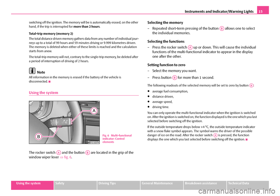
The rocker switch and the button are located in the grip of the
window wiper lever ⇒fig. 6 . Selecting the memory
– Repeated short-term pressing of the button allows one to select
the individual memories.
Selecting the functions
– Press the rocker switch up or down. This will cause the individual functions of the multi-functional in dicator to appear in the display
one after the other.
Setting function to zero
– Select the memory you want.
– Press button for more than 1 second.
The following readouts of the selected me mory will be set to zero by button :
•average fuel consumption,
•distance driven,
•average speed,
•driving time.
You can only operate the multi-functional indicator when the ignition is switched
on. After the ignition is switched on, the fu nction displayed is the one which you last
selected before switching off the ignition.
If the outside temperature drops below +4 °C, the outside temperature indicator
with a snow flake symbol appears. The symbol warns the driver of the possible
danger of ice on the road. After the rocker switch is pressed, the function
displays the one which you last selected before switching off the ignition.
Fig. 6 Multi-functional
indicator: Control
elements
AAAB
AB
AA
AB
AB
AA
NKO A5 20 MR08.book Page 15 Wednesday, April 11, 2007 2:54 PM
Page 18 of 288
Instruments and Indicator/Warning Lights17
Using the systemSafetyDriving TipsGeneral MaintenanceBreakdown assistanceTechnical Data
you must first erase the memory at this moment in time by pressing the button
⇒
page 15, fig. 6 .
The maximum distance indicated in both switch positions is 9999 km. The indicator
is set back to null if this period is exceeded.
Average speed
The average speed since the memory was last erased is shown in the display in
km/hour ⇒page 14. If you wish to determine the average speed over a certain
period of time you must first erase the memory at the start of the new measure-
ment using the button ⇒page 15, fig. 6 .
A zero appears in the display for the first 100 m you drive after erasing the memory.
The indicated value will be updated every 5 seconds while you are driving.
Driving time
The driving time which has elapsed since the memory was last erased, appears in
the display ⇒page 14. If you wish to calculate th e driving time from a particular
time of day you must first erase the memory at this moment in time by pressing the
button ⇒page 15, fig. 6 .
The maximum distance indicated in both memories is 99 hours and 59 minutes.
The indicator is set back to nu ll if this period is exceeded.
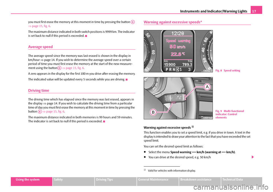
Warning against excessive speeds*
Warning against excessive speeds 1)
This function enables you to set a speed limit, e.g. if you drive in town. A text in the
display is intended to draw your attention to the fact that you have exceeded the set
speed limit.
You can set the desired speed limit as follows:
•Select the menu Speed warning --- km/h (warning at --- km/h) .
•You can drive at the desired speed, e.g. 50 km/h
AB
AB
AB
1)Valid for vehicles with information display.
Fig. 8 Speed setting
Fig. 9 Multi-functional
indicator: Control
elements
NKO A5 20 MR08.book Page 17 Wednesday, April 11, 2007 2:54 PM
Page 20 of 288
Instruments and Indicator/Warning Lights19
Using the systemSafetyDriving TipsGeneral MaintenanceBreakdown assistanceTechnical Data
Main menu
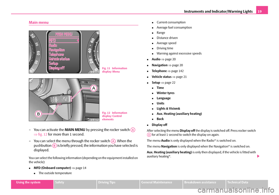
– You can activate the MAIN MENU by pressing the rocker switch
⇒ fig. 12 for more than 1 second.
– You can select the menu through the rocker switch . When the pushbutton is briefly pressed, the information you have selected is
displayed.
You can select the following information (depending on the equipment installed on
the vehicle):
�„MFD (Onboard computer) ⇒ page 14
�„The outside temperature
�„Current consumption
�„Average fuel consumption
�„Range
�„Distance driven
�„Average speed
�„Driving time
�„Warning against excessive speeds
�„Audio ⇒ page 20
�„Navigation ⇒ page 20
�„Te l e p h o n e ⇒ page 142
�„Vehicle status ⇒ page 21
�„Setup ⇒ page 22
�„Time
�„Winter tyres
�„Language
�„Units
�„Lights & Vision&
�„Aux. Heating (auxiliary heating)
�„Back
�„Display off
After selecting the menu Display off the display is switched off. Press rocker switch
for at least 1 second to switch the display on again.
The menu Audio is only displayed when th e Radio* is switched on.
The menu Navigation is only displayed when the Navigation* is switched on.
Aux. Heating (auxiliary heating) is only then displayed, if the vehicle is fitted with
auxiliary heating*.
Fig. 11 Information
display: Menu
Fig. 12 Information
display: Control
elements
AA
AA
AB
AA
NKO A5 20 MR08.book Page 19 Wednesday, April 11, 2007 2:54 PM
Page 22 of 288
Instruments and Indicator/Warning Lights21
Using the systemSafetyDriving TipsGeneral MaintenanceBreakdown assistanceTechnical Data
Auto Check Control*
Car state
The Auto Check Control carries out a check of certain functions and vehicle compo-
nents. The check is performed constantly when the ignition is switched on, both
when the vehicle is stationary, as well as when driving.
Operational faults, urgent repairs, service work or other information appear in the
display of the instrument cluster. The disp lays are shown with a red or yellow light
symbol depending on the priority of the message.
The red symbols indicate danger (priority 1) while the yellow symbols indicate a
warning (priortity 2). Information for the driver may also appear in addition to the
symbols ⇒page 24.
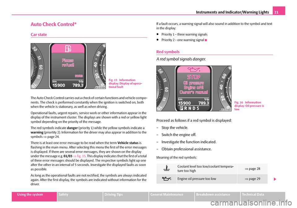
There is at least one error message to be read when the term Vehicle status is
flashing in the main menu. After selecting this menu the first of the error messages
is displayed. If there are several error messages, they are shown on the display
under the message e.g. 01/03 ⇒ fig. 15 . This display indicates that the first of a total
of three error messages should be displa yed. The respective symbols light up one
after the other in an interval of 5 seconds. Investigate the displayed faults as soon
as possible.
As long as the operational faults are not rectified, the symbols are always indicated
again. After the first display, the symbols are indicated without information for the
driver. If a fault occurs, a warning signal will also sound in addition to the symbol and text
in the display:
•Priority 1 - three warning signals
•Priority 2 - one warning signal
Red symbols
A red symbol signals danger.
Proceed as follows if a red symbol is displayed:
– Stop the vehicle.
– Switch the engine off.
– Investigate the function indicated.
– Obtain professional assistance.
Meaning of the red symbols:
Fig. 15 Information
display: Display of opera-
tional fault
Coolant level too low/coolant tempera-
ture too high⇒
page 28
Engine oil pressure too low⇒page 29
Fig. 16 Information
display: Oil pressure is
low
NKO A5 20 MR08.book Page 21 Wednesday, April 11, 2007 2:54 PM
Page 24 of 288
Instruments and Indicator/Warning Lights23
Using the systemSafetyDriving TipsGeneral MaintenanceBreakdown assistanceTechnical Data
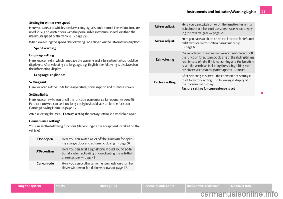
Setting for winter tyre speed
Here you can set at which speed a warning
signal should sound. These functions are
used for e.g on winter tyres with the permissible maximum speed less than the
maximum speed of the vehicle ⇒page 225.
When exceeding the speed, the following is displayed on the information display*: Speed warning
Language setting
Here you can set in which language the warning and information texts should be
displayed. After selecting the language, e. g. English, the following is displayed on
the information display:
Language: english set
Setting units
Here you can set the units for temperat ure, consumption and distance driven.
Setting lights
Here you can switch on or off the function convenience turn signal ⇒page 56.
Furthermore you can set how long the li ght should stay on for the function
Coming/Leaving Home ⇒page 53.
After selecting the menu Fa cto r y se tt ing the factory setting is established again.
Convenience setting*
You can set the following functions (depending on the equipment installed on the
vehicle):
Door openHere you can switch on or off the functions for open-
ing a single door and automatic closing ⇒page 37.
ATA c onfir mHere you can set if a signal tone should sound addi-
tionally when activating or deactivating the anti-theft
alarm system ⇒page 43.
Conv. modeHere you can set the convenience mode only for the
driver window or for all the windows ⇒page 47.
Mirror adjust.Here you can switch on or off the function for mirror
adjustment on the front pa ssenger side when engag-
ing the reverse gear ⇒page 65.
Mirror adjust.Here you can switch on or off the function for left and
right exterior mirror setting simultaneously
⇒page 65.
Rain-closing
On vehicles with rain sensor you can switch on or off
the function for automatic closing of the sliding/tilting
roof in case of rain. If it is not raining and the function
is set, the windows including the sliding/tilting roof
are closed automatically after approx. 12 hours.
Fa ct or y se t tin g
After selecting this menu the convenience setting is
reset to factory setting. The following is displayed in
the information display:
Factory setting for convenience is set
.
NKO A5 20 MR08.book Page 23 Wednesday, April 11, 2007 2:54 PM
Page 26 of 288
Instruments and Indicator/Warning Lights25
Using the systemSafetyDriving TipsGeneral MaintenanceBreakdown assistanceTechnical Data
WARNING
•If you do not pay attention to the warning lights coming on and the corre-
sponding descriptions and warning notes, this may result in severe body
injuries or major vehicle damage.
•The engine compartment of your car is a hazardous area. There is a risk
of injuries, scalding, accidents and fire when working in the engine
compartment, e.g. inspecting and replenis hing oil and other fluids. It is also
essential to observe all warnings ⇒page 210.
Note
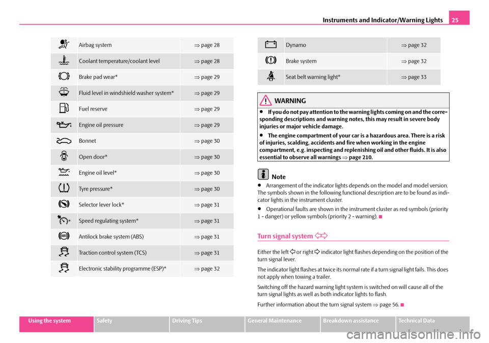
•Arrangement of the indicator lights de pends on the model and model version.
The symbols shown in the following function al description are to be found as indi-
cator lights in the instrument cluster.
•Operational faults are shown in the instrument cluster as red symbols (priority
1 - danger) or yellow symbols (priority 2 - warning).
Turn signal system
Either the left or right indicator light flashes depending on the position of the
turn signal lever.
The indicator light flashes at twice its normal rate if a turn signal light fails. This does
not apply when towing a trailer.
Switching off the hazard warning light system is switched on will cause all of the
turn signal lights as well as both indicator lights to flash.
Further information about the turn signal system ⇒page 56.
Airbag system⇒page 28
Coolant temperature/coolant level⇒page 28
Brake pad wear*⇒page 29
Fluid level in windshield washer system*⇒page 29
Fuel reserve⇒page 29
Engine oil pressure⇒page 29
Bonnet⇒page 30
Open door*⇒page 30
Engine oil level*⇒page 30
Tyre pressure*⇒page 30
Selector lever lock*⇒page 31
*Speed regulating system*⇒page 31
Antilock brake system (ABS)⇒page 31
Traction control system (TCS)⇒page 31
Electronic stability programme (ESP)*⇒page 32
Dynamo⇒page 32
Brake system⇒page 32
Seat belt warning light*⇒page 33
NKO A5 20 MR08.book Page 25 Wednesday, April 11, 2007 2:54 PM