wheel SKODA OCTAVIA 2007 1.G / (1U) User Guide
[x] Cancel search | Manufacturer: SKODA, Model Year: 2007, Model line: OCTAVIA, Model: SKODA OCTAVIA 2007 1.G / (1U)Pages: 288, PDF Size: 15.19 MB
Page 78 of 288
Seats and Stowage77
Using the systemSafetyDriving TipsGeneral MaintenanceBreakdown assistanceTechnical Data
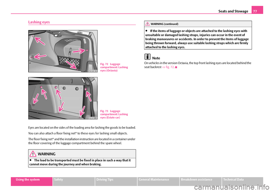
Lashing eyes
Eyes are located on the sides of the loading area for lashing the goods to be loaded.
You can also attach a floor fixing net* to these eyes for lashing small objects.
The floor fixing net* and the installation instruction are located in a container under
the floor covering of the luggage compartment behind the spare wheel.
WARNING
•The load to be transported must be fi xed in place in such a way that it
cannot move during the journey and when braking.
•If the items of luggage or objects ar e attached to the lashing eyes with
unsuitable or damaged lashing straps, injuries can occur in the event of
braking manoeuvres or accidents. In order to prevent the items of luggage
being thrown forward, always use suit able lashing straps which are firmly
attached to the lashing eyes.
Note
On vehicles in the version Octavia, the top front lashing eyes are located behind the
seat backrest ⇒fig. 72 .Fig. 72 Luggage
compartment: Lashing
eyes (Octavia)
Fig. 73 Luggage
compartment: Lashing
eyes (Estate car)
WARNING (continued)
NKO A5 20 MR08.book Page 77 Wednesday, April 11, 2007 2:54 PM
Page 79 of 288
Seats and Stowage
78
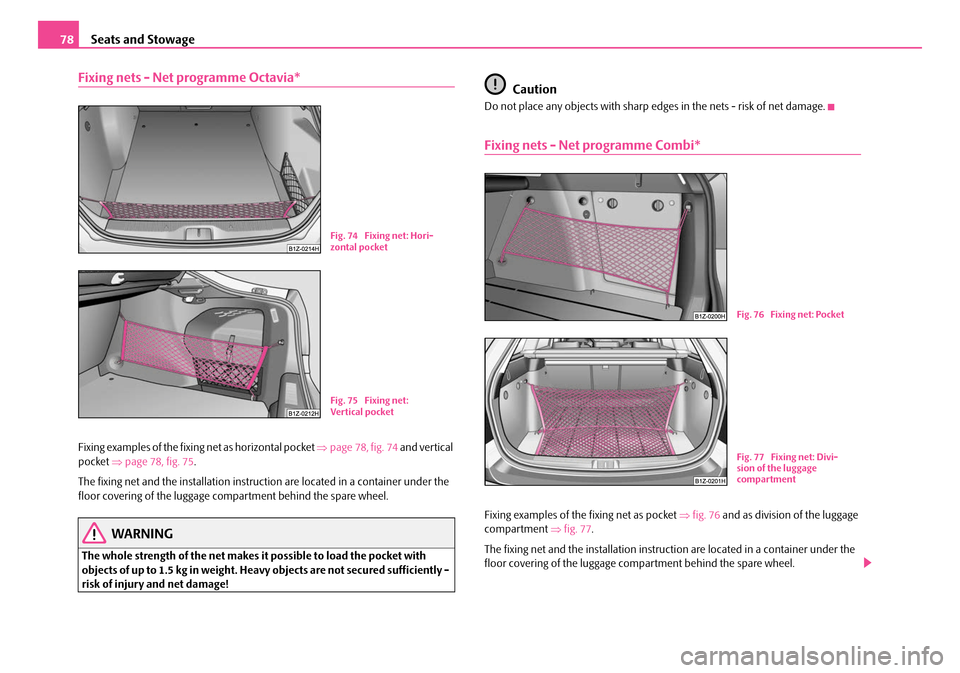
Fixing nets - Net programme Octavia*
Fixing examples of the fixing net as horizontal pocket ⇒page 78, fig. 74 and vertical
pocket ⇒page 78, fig. 75 .
The fixing net and the installation instru ction are located in a container under the
floor covering of the luggage co mpartment behind the spare wheel.
WARNING
The whole strength of the net makes it possible to load the pocket with
objects of up to 1.5 kg in weight. Heavy objects are not secured sufficiently -
risk of injury and net damage!
Caution
Do not place any objects with sharp edges in the nets - risk of net damage.
Fixing nets - Net programme Combi*
Fixing examples of the fixing net as pocket ⇒fig. 76 and as division of the luggage
compartment ⇒ fig. 77.
The fixing net and the installation instru ction are located in a container under the
floor covering of the luggage co mpartment behind the spare wheel.
Fig. 74 Fixing net: Hori-
zontal pocket
Fig. 75 Fixing net:
Ver tical pocket
Fig. 76 Fixing net: Pocket
Fig. 77 Fixing net: Divi-
sion of the luggage
compartment
NKO A5 20 MR08.book Page 78 Wednesday, April 11, 2007 2:54 PM
Page 81 of 288
Seats and Stowage
80
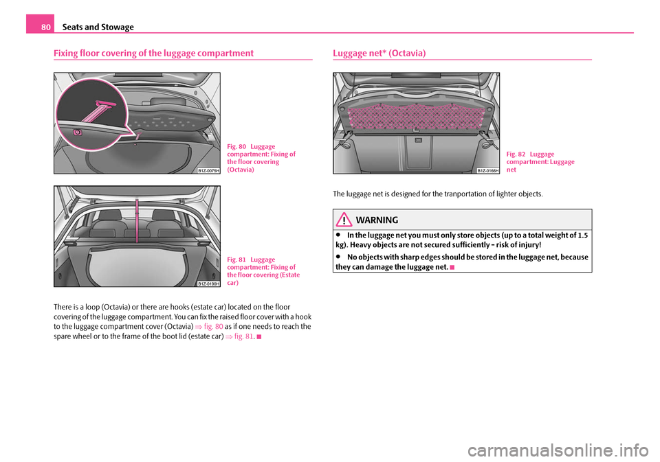
Fixing floor covering of the luggage compartment
There is a loop (Octavia) or there are hooks (estate car) located on the floor
covering of the luggage compartment. You can fix the raised floor cover with a hook
to the luggage compartment cover (Octavia) ⇒fig. 80 as if one needs to reach the
spare wheel or to the frame of the boot lid (estate car) ⇒fig. 81 .
Luggage net* (Octavia)
The luggage net is designed for the tranportation of lighter objects.
WARNING
•In the luggage net you must only store objects (up to a total weight of 1.5
kg). Heavy objects are not secured sufficiently - risk of injury!
•No objects with sharp edges should be stored in the luggage net, because
they can damage the luggage net.
Fig. 80 Luggage
compartment: Fixing of
the floor covering
(Octavia)
Fig. 81 Luggage
compartment: Fixing of
the floor covering (Estate
car)
Fig. 82 Luggage
compartment: Luggage
net
NKO A5 20 MR08.book Page 80 Wednesday, April 11, 2007 2:54 PM
Page 103 of 288
Heating and air conditioning system
102
The control dial can be set to other positions as required.
Recirculated air mode
In recirculated air mode air is sucked out of the interior of the vehicle
and then fed back into the interior.
Recirculated air mode prevents polluted air outside the vehicle from
getting into the vehicle, for example when driving through a tunnel or
when standing in a traffic jam.
Switching recirculated air mode on
– Press the button - the warning light lights up in the button
⇒page 100, fig. 119 .
Switching recirculated air mode off
– Press again the button - the warning light in the button goes out.
The recirculated air mode is switched off au tomatically if the air distribution control
is in position ⇒ page 100, fig. 119 . You can also switch recirculated air mode
on again from this setting by repeatedly pressing button .
WARNING
You should not leave recirculated air mode on over a longer period of time,
as “stale” air may result in fatigue in the driver and occupants, divert your
attention and also cause the windows to mist up. The risk of having an acci-
dent increases. Switch recirculated air mode off as soon as the windows
begin misting up.
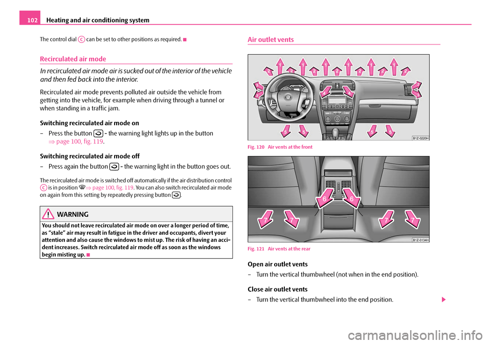
Air outlet vents
Fig. 120 Air vents at the front
Fig. 121 Air vents at the rear
Open air outlet vents
– Turn the vertical thumbwheel (not when in the end position).
Close air outlet vents
– Turn the vertical thumbwheel into the end position.
AC
AC
NKO A5 20 MR08.book Page 102 Wednesday, April 11, 2007 2:54 PM
Page 104 of 288
Heating and air conditioning system103
Using the systemSafetyDriving TipsGeneral MaintenanceBreakdown assistanceTechnical Data
Redirecting air flow
– Swivel upward or downward the grille of the vents in order to change
the direction of the air flow using the vertically arranged thumbwheel.
– Turn the horizontal thumbwheel on the v e n t t o t h e r i g h t o r l e f t i n o rd e r
to change the air flow to the appropriate side.
You can set the air supply to the individual air outlet vents using the control dial
⇒ page 100, fig. 119 . Air outlet vents 3, 4 ⇒ page 102, fig. 120 and 6 ⇒ page 102,
fig. 121 can also be opened or closed individually.
The air outlet vents 6 are only fitted on vehicles with higher centre console.
Unwarmed or cooled air will flow out of the opened air outlet vents according to
the setting of the control dial ⇒page 100, fig. 119 and according to outer
atmospheric conditions.
Note
The air outlet vents 2 ensure in the ventilation mode for a comfortable (no-draught)
ventilation of the interior of the vehicle, also if the air outlet vents 4 are closed.
Climatic* (semi-automatic air conditioning system)
Description
The Climatic is a combined coolin g and heating system. It makes it
possible to optimally control the air temperature at any season of the
year.
Description of the Climatic
It is important for your safety and for your driving comfort that the Climatic is oper-
ating properly.
The cooling only operates if button ⇒page 104, fig. 122 is pressed, and the
following conditions are met:
•engine running,
•outside temperature above +2 °C and
•blower switch switched on (positions 1 to 4).
If the cooling system is switched on, th e temperature and air humidity drops in the
vehicle. The wellbeing of the occupants of the car is enhanced as a result of this
particularly at high outside temperatur es and a high air humidity. The system
prevents the windows misting up during the cold season of the year.
The heating effect is dependent upon th e coolant temperature, thus full heat
output only occurs when the engine has reached its operating temperature.
It is possible to briefly activate recirc ulated air mode in order to enhance the
cooling effect ⇒.
Air at a temperature of about 5°C may flow out of the vents under certain circum-
stances when the cooling system is operating. Lengthy and uneven distribution of
the air flow out of the vents (in particular at the leg area) and large differences in
temperature, for example when getting out of the vehicle, can result in chills in
sensitive persons.
The air inlet in front of the windscreen must be free of ice, snow or leaves in order
to ensure that the heating and cooling systems operate properly.
After switching on the cooling Condensation from the evaporator of the air condi-
tioning may drip down and form a puddle below the vehicle. This is quite normal
and not an indication of a leak!
WARNING
•For your own safety and that of other road users, ensure that all the
windows are free of ice, snow and mistin g. Please familiarize yourself about
how to correctly operate th e heating and ventilation systems, how to demist
and defrost the windows, as well as with the cooling mode.
•You should not leave recirculated air mode on over a longer period of
time, as “stale” air may result in fatigue in the driver and occupants, divert
your attention and also cause the windows to mist up. The risk of having an
accident increases. Switch recirculated air mode off as soon as the windows
begin misting up.
AC
AA
ACA1
NKO A5 20 MR08.book Page 103 Wednesday, April 11, 2007 2:54 PM
Page 108 of 288
Heating and air conditioning system107
Using the systemSafetyDriving TipsGeneral MaintenanceBreakdown assistanceTechnical Data
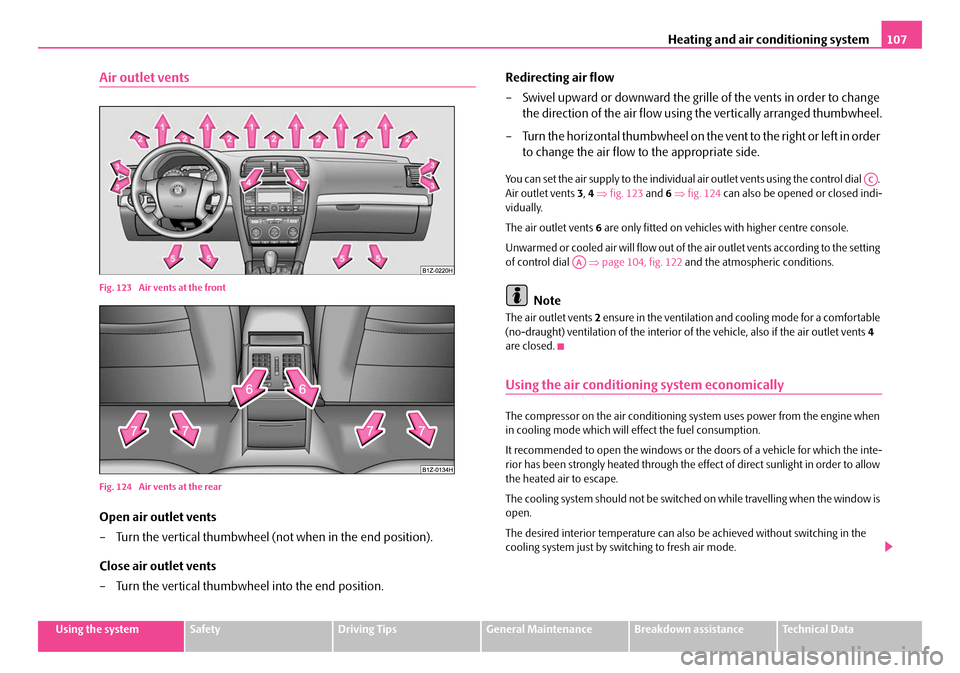
Air outlet vents
Fig. 123 Air vents at the front
Fig. 124 Air vents at the rear
Open air outlet vents
– Turn the vertical thumbwheel (not when in the end position).
Close air outlet vents
– Turn the vertical thumbwheel into the end position. Redirecting air flow
– Swivel upward or downward the grille of the vents in order to change
the direction of the air flow using the vertically arranged thumbwheel.
– Turn the horizontal thumbwheel on the vent to the right or left in order to change the air flow to the appropriate side.
You can set the air supply to the individual air outlet vents using the control dial .
Air outlet vents 3, 4 ⇒ fig. 123 and 6 ⇒ fig. 124 can also be opened or closed indi-
vidually.
The air outlet vents 6 are only fitted on vehicles with higher centre console.
Unwarmed or cooled air will flow out of the air outlet vents according to the setting
of control dial ⇒page 104, fig. 122 and the atmosphe ric conditions.
Note
The air outlet vents 2 ensure in the ventilation and cooling mode for a comfortable
(no-draught) ventilation of the interior of the vehicle, also if the air outlet vents 4
are closed.
Using the air conditioning system economically
The compressor on the air conditioning sy stem uses power from the engine when
in cooling mode which will effect the fuel consumption.
It recommended to open the windows or the doors of a vehicle for which the inte-
rior has been strongly heated through the effect of di rect sunlight in order to allow
the heated air to escape.
The cooling system should not be switched on while travelling when the window is
open.
The desired interior temperature can also be achieved without switching in the
cooling system just by sw itching to fresh air mode.
AC
AA
NKO A5 20 MR08.book Page 107 Wednesday, April 11, 2007 2:54 PM
Page 113 of 288
Heating and air conditioning system
112
The set blower speed is displayed above the control dial when the respective
number of warning lights come on.
WARNING
•“Stale air” may result in fatigue in the driver and occupants, reduce
attention levels and also cause the windows to mist up. The risk of having an
accident increases.
•Do not switch the Climatronic system off for longer than necessary.
•Switch the Climatronic system on as soon as the windows mist up.
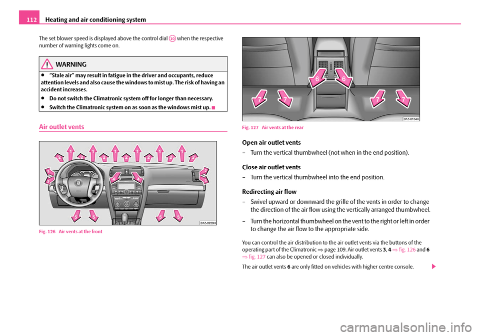
Air outlet vents
Fig. 126 Air vents at the front Fig. 127 Air vents at the rear
Open air outlet vents
– Turn the vertical thumbwheel (not when in the end position).
Close air outlet vents
– Turn the vertical thumbwheel into the end position.
Redirecting air flow
– Swivel upward or downward the grille of the vents in order to change
the direction of the air flow using the vertically arranged thumbwheel.
– Turn the horizontal thumbwheel on the vent to the right or left in order to change the air flow to the appropriate side.
You can control the air distribution to the air outlet vents via the buttons of the
operating part of the Climatronic ⇒page 109. Air outlet vents 3, 4 ⇒ fig. 126 and 6
⇒ fig. 127 can also be opened or closed individually.
The air outlet vents 6 are only fitted on vehicles with higher centre console.
A10
NKO A5 20 MR08.book Page 112 Wednesday, April 11, 2007 2:54 PM
Page 117 of 288
Starting-off and Driving
116
Starting-off and Driving
Setting steering wheel position
You can set the height and the forward/back position of the steering
wheel to the desired position.
– Adjust the driver seat ⇒page 67.
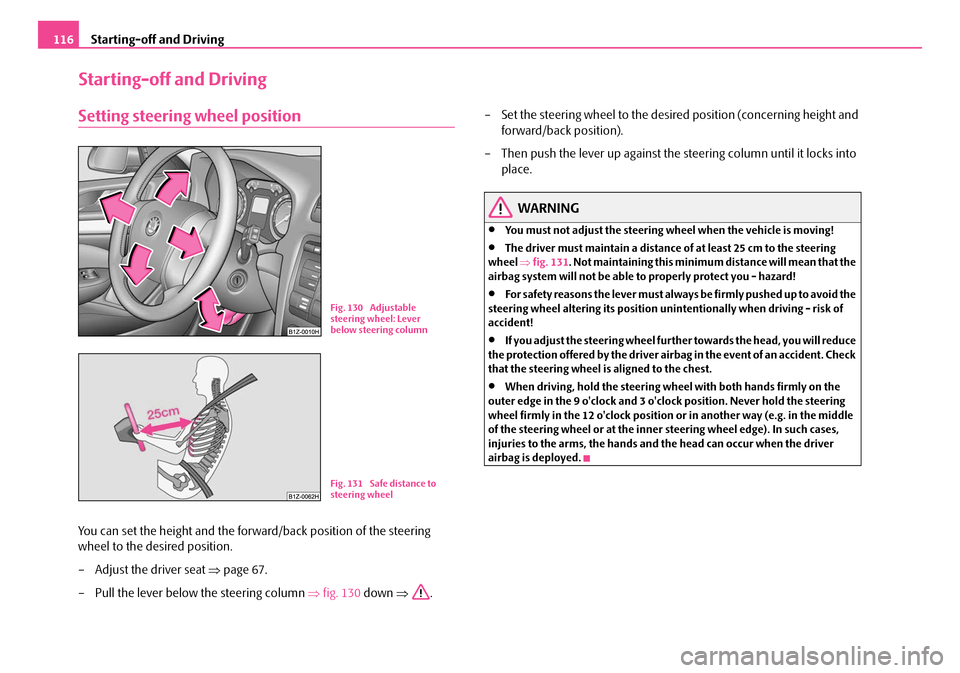
– Pull the lever below the steering column ⇒fig. 130 down ⇒. – Set the steering wheel to the desired position (concerning height and
forward/back position).
– Then push the lever up against the steering column until it locks into
place.
WARNING
•You must not adjust the steering wh eel when the vehicle is moving!
•The driver must maintain a distance of at least 25 cm to the steering
wheel ⇒fig. 131 . Not maintaining this minimum distance will mean that the
airbag system will not be able to properly protect you - hazard!
•For s afe ty re a so ns t he le ve r m ust al wa y s b e fi rm ly pus he d up to a voi d the
steering wheel alteri ng its position unintentionally when driving - risk of
accident!
•If you adjust the steering wheel furthe r towards the head, you will reduce
the protection offered by the driver airb ag in the event of an accident. Check
that the steering wheel is aligned to the chest.
•When driving, hold the steering wheel with both hands firmly on the
outer edge in the 9 o'clock and 3 o'clock position. Never hold the steering
wheel firmly in the 12 o'clock position or in another way (e.g. in the middle
of the steering wheel or at the inner steering wheel edge). In such cases,
injuries to the arms, the hands and the head can occur when the driver
airbag is deployed.
Fig. 130 Adjustable
steering wheel: Lever
below steering column
Fig. 131 Safe distance to
steering wheel
NKO A5 20 MR08.book Page 116 Wednesday, April 11, 2007 2:54 PM
Page 118 of 288
Starting-off and Driving117
Using the systemSafetyDriving TipsGeneral MaintenanceBreakdown assistanceTechnical Data
Ignition lock
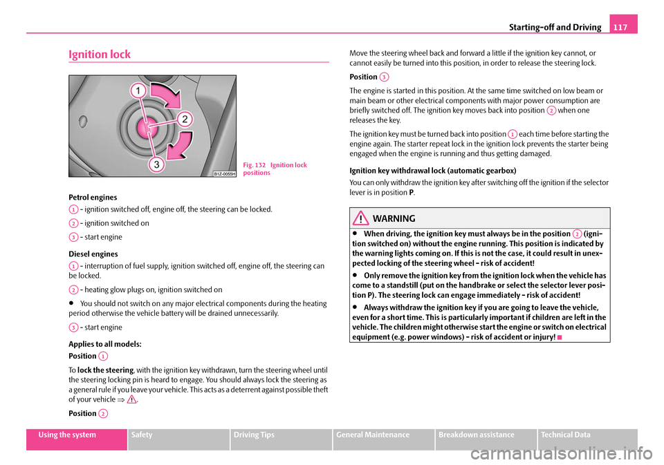
Petrol engines
- ignition switched off, engine off, the steering can be locked.
- ignition switched on
- start engine
Diesel engines - interruption of fuel supply, ignition switched off, engine off, the steering can
be locked.
- heating glow plugs on, ignition switched on
•You should not switch on any major elec trical components during the heating
period otherwise the vehicle batter y will be drained unnecessarily.
- start engine
Applies to all models:
Position
To lock the steering , with the ignition key withdrawn, turn the steering wheel until
the steering locking pin is heard to engage. You should always lock the steering as
a general rule if you leave your vehicle. This acts as a deterrent against possible theft
of your vehicle ⇒.
Position Move the steering wheel back and forward
a little if the ignition key cannot, or
cannot easily be turned into this position, in order to release the steering lock.
Position
The engine is started in this position. At the same time switched on low beam or
main beam or other electrical compon ents with major power consumption are
briefly switched off. The ignition key moves back into position when one
releases the key.
The ignition key must be turned back into position each time before starting the
engine again. The starter repeat lock in th e ignition lock prevents the starter being
engaged when the engine is ru nning and thus getting damaged.
Ignition key withdrawal lock (automatic gearbox)
You can only withdraw the ignition key after switching off the ignition if the selector
lever is in position P.
WARNING
•When driving, the ignition key must always be in the position (igni-
tion switched on) without the engine running. This position is indicated by
the warning lights coming on. If this is not the case, it could result in unex-
pected locking of the steering wheel - risk of accident!
•Only remove the ignition key from the ignition lock when the vehicle has
come to a standstill (put on the handbrake or select the selector lever posi-
tion P). The steering lock can enga ge immediately - risk of accident!
•Always withdraw the ignition key if you are going to leave the vehicle,
even for a short time. This is particularly important if children are left in the
vehicle. The children might otherwise star t the engine or switch on electrical
equipment (e.g. power windows) - risk of accident or injury!
Fig. 132 Ignition lock
positions
A1
A2
A3
A1
A2
A3
A1
A2
A3
A2
A1
A2
NKO A5 20 MR08.book Page 117 Wednesday, April 11, 2007 2:54 PM
Page 128 of 288
Automatic gearbox127
Using the systemSafetyDriving TipsGeneral MaintenanceBreakdown assistanceTechnical Data
•When the engine is running and the vehicle is stationary, it is necessary
to hold the car with the brake pedal in all the positions of the selector lever
(except P and N) since the power transmission is never completely inter-
rupted, also not when the engine is idling - the vehicle "creeps".
Selector lever positions
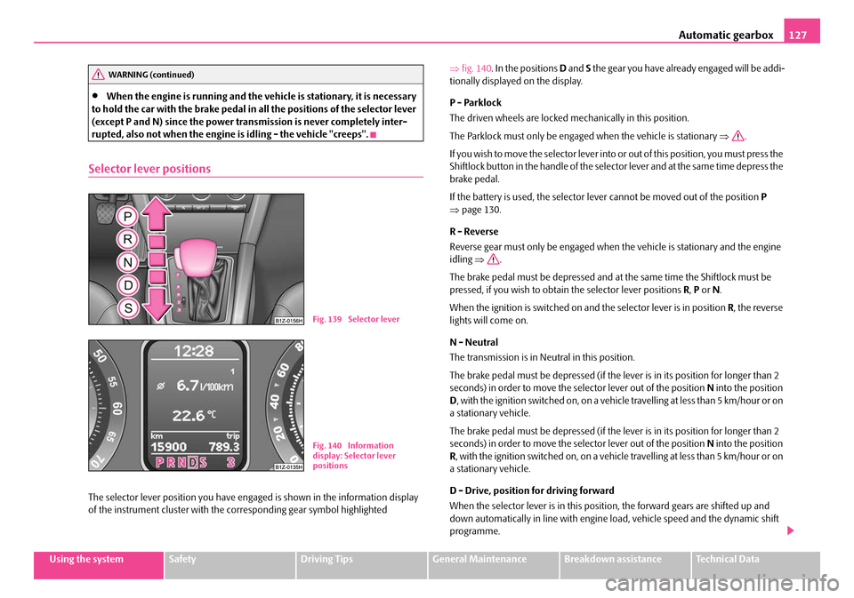
The selector lever position you have engaged is shown in the information display
of the instrument cluster with the co rresponding gear symbol highlighted ⇒
fig. 140 . In the positions D and S the gear you have already engaged will be addi-
tionally displayed on the display.
P - Parklock
The driven wheels are locked me chanically in this position.
The Parklock must only be engage d when the vehicle is stationary ⇒.
If you wish to move the select or lever into or out of this position, you must press the
Shiftlock button in the handle of the select or lever and at the same time depress the
brake pedal.
If the battery is used, the selector le ver cannot be moved out of the position P
⇒ page 130.
R - Reverse
Reverse gear must only be engaged when the vehicle is stationary and the engine
idling ⇒ .
The brake pedal must be depressed and at the same time the Shiftlock must be
pressed, if you wish to obtain the selector lever positions R, P or N.
When the ignition is switched on and the selector lever is in position R, the reverse
lights will come on.
N - Neutral
The transmission is in Neutral in this position.
The brake pedal must be depressed (if the le ver is in its position for longer than 2
seconds) in order to move the selector lever out of the position N into the position
D , with the ignition switched on, on a vehicle travelling at less than 5 km/hour or on
a stationary vehicle.
The brake pedal must be depressed (if the le ver is in its position for longer than 2
seconds) in order to move the selector lever out of the position N into the position
R , with the ignition switched on, on a vehicl e travelling at less than 5 km/hour or on
a stationary vehicle.
D - Drive, position for driving forward
When the selector lever is in this position, the forward gears are shifted up and
down automatically in line with engine load, vehicle speed and the dynamic shift
programme.
WARNING (continued)
Fig. 139 Selector lever
Fig. 140 Information
display: Selector lever
positions
NKO A5 20 MR08.book Page 127 Wednesday, April 11, 2007 2:54 PM