ECU SKODA OCTAVIA 2007 1.G / (1U) Owner's Guide
[x] Cancel search | Manufacturer: SKODA, Model Year: 2007, Model line: OCTAVIA, Model: SKODA OCTAVIA 2007 1.G / (1U)Pages: 288, PDF Size: 15.19 MB
Page 151 of 288

Communication
150
Input AUX-IN*
The input for external audio sources AUX-IN is located below the armrest of the
front seat and is marked with This input serves for connecting external audio
sources (e.g. portable mp3 player) to th e your radio system. The equipment AUX-
IN* can only be used in combination with a radio or navigation system installed in
the factory. The description on how to operate AUX-IN* can be found in the rele-
vant operating instructions of the radio or the navigation system Nexus.
Note
If an external audio source is connected via AUX-IN, which has a separate power
supply, this can lead to an interference of the audio signals. It depends on the prop-
erties of the adapter.
CD changer*
The CD changer for the radio and navigation system is located in the left
side compartment of the luggage compartment. Loading a CD
– Touch the button and guide the
CD (compact disc) into the CD-
case . The CD is automatically loaded onto the next free position in
the CD-changer. The LED in the corresponding button stops
flashing.
Loading all CDs
– Hold the button pressed and guide all CDs one after the other into the CD-case . The LEDs in the buttons are no longer flashing.
Loading a CD to one definite position
– Touch button . The LEDs in the buttons light up at the memory spaces, which are already assigned and flash in the case of free
memory spaces.
– Touch the desired button and guide the CD into the CD-case .
Ejecting a CD
– Touch the button , in order to eject a CD. For assigned memory spaces, now the LEDs light up in the buttons .
– Touch the corresponding button . The CD is ejected.
Ejecting all CDs
– Hold the button pressed for more th an 2 seconds, in order to eject
the CDs. All CDs in the CD-changer are ejected consecutively.
Note•Always guide the CD into the CD-cas e with the printed side pointing
upwards.
•Never push the CD with force into the CD-case as the insertion is performed
automatically.
Fig. 154 The CD changer
AC
AB
AD
AC
ABAD
ACAD
ADAB
AA
AD
AD
AA
AB
NKO A5 20 MR08.book Page 150 Wednesday, April 11, 2007 2:54 PM
Page 174 of 288

Transporting children safely173
Using the systemSafetyDriving TipsGeneral MaintenanceBreakdown assistanceTechnical Data
Transporting children safely
What you should know about transporting children!
An introduction to the subject
Accident statistics have revealed that children are generally more
safely transported on the rear seat s than on the front passenger seat.
Children younger than 12 years of age should normally travel on the rear seat of the
vehicle (take note of any na tional legal provisions which differ from this). They
should be secured there by means of a child restraint system or by using the existing
seat belts depending on their age, body si ze and weight. The child seat should be
mounted behind the front passen ger seat for safety reasons.
The physical principle of an accident do es, of course, also apply to children
⇒ page 159, “The physical principle of a fronta l collision”. They differ from adults in
that their muscles and bone structure of ch ildren are not yet fully developed. Thus
children are exposed to increased risk of injury.
Children should be transported by using special child safety seats in order to
reduce this risk of injury.
Use only child safety seats which are offici ally approved and are suitable for chil-
dren and which comply with the ECE-R 44 Standard, which classifies child safety
seats into 5 groups ⇒page 176, “Classification of child seats into groups”. Child
restraint systems which have been tested for conformity with ECE-R 44 have a non-
detachable test seal (a large E within a circle and below this the test number)
attached to the seat.
We recommend that you use ch ild safety seats from the Škoda genuine accessories.
These child seats were developed and also tested for use in Škoda vehicles. They
fulfil the standard ECE-R 44.
WARNING
Always comply with legal provisions and instructions from the relevant child
safety seat manufacturer when in stalling and using the child seat ⇒ in
“Important safety information regarding the use of child safety seats”.
Note
Any varying national legal regulations take priority over the information provided in
these instructions for use, or stated in this chapter.
Important safety information regarding the use of child safety
seats
Correct use of child safety seats considerably reduces the risk of
injury!
WARNING
•All the occupants of the car - in particular children - must wear a seat belt
when the car is moving.
•Chi ld re n le s s tha n 1. 5 0 m i n h e ig ht or younger than 12 years must not use
a normal seat belt withou t a child restraint system otherwise this may result
in injuries to the stomach and neck areas. Comply with the national legal
requirements.
•One should never carry children, and also not babies! - on one's lap.
•You can transport a child safely in a suitable child safety seat ⇒page 176,
“Child seat”!
•Only one child may be fastened with a seat belt into a child safety seat.
•Never leave the child sitting unattended in the seat.
•Certain outside climatic conditions can cause life-threatening tempera-
tures in the vehicle.
•Never allow your child to be transported in a vehicle without the use of a
suitable restraint system.
•Children should also never stand up in a vehicle or kneel on the seats
when the vehicle is moving. In the event of an accident the child will be
thrown through the vehicle and may as a result suffer fatal injuries, and also
injure other occupants.
NKO A5 20 MR08.book Page 173 Wednesday, April 11, 2007 2:54 PM
Page 197 of 288
Towing a trailer
196
Towing a trailer
To w i n g a t r a i l e r
Technical requirements
The towing device must satisfy certain technical requirements.
Your vehicle is designed primarily for tr ansporting persons and luggage. It can,
however, also be used for towing a traile r - provided certain technical equipment is
fitted.
If your vehicle has already been supplied with a factory-fitted towing device then
everything that is necessary for towing a trailer in technical terms, and in terms of
the law, has already been taken into account.
Your vehicle is fitted with a 13-pin power socket for the electrical connection
between the vehicle and trailer. If th e trailer which you wish to tow has a 7-pin
connector, you can use a suitable adapter
10) from Škoda original accessories.
This work must be carried out in accordan ce with the manufacturer's specifications
if a towing device is retrofitted.
Škoda Service Partners are familiar with de tails relating to retrofitting a towing
device and for any necessary modi fications to the cooling system.
WARNING
We recommend that you have the towing device from Škoda original acces-
sories installed by a Škoda Service Partner. He is familiar with all the relevant
details relating to retrofitting such equi pment. There is a risk of an accident
if the towing device is not properly fitted!
General Maintenance
There are a number of points to pay attention to when towing a
trailer.
Trailer load
The permissible trailer load must on no account be exceeded.
You can negotiate appropriately steeper inclines and descents if you do not make
full use of the perm issible trailer load.
The trailer loads specified only apply for altitudes up to 1 000 metres above mean
sea level. The fact that the engine power ou tput drops with increasing height due to
a lowering of air pressure and thus the abil ity to climb, means that the towed weight
must be reduced by 10% for every further increase of 1 000 metres in height above
sea level. The towed weight is the weight of the (laden) vehicle and the (laden)
trailer together. One should take this into account before driving up to higher alti-
tudes.
The trailer and drawbar load information on the type plate of the towing
device are merely test data for the tow ing device The data relating to your
vehicle, which is often less than this test data, can be found in your vehicle
registration documents.
Distribution of the load
Distribute the load in the trailer in such a way that any heavy items are located as
close as possible to the axle. Secure the items to prevent them slipping.
Tyre inflation pressure
Select the tyre inflation pressure on your vehicle for that of “fully laden”,
⇒ page 223. The inflation pressure of the tyres fitted to the trailer adjust in accord-
ance with the manufacturer's recommendation.
Exterior mirrors
You have to have additional exterior mirrors fitted if you are not able to see the
traffic behind the trailer with the standard rear-view mirrors. Both exterior mirrors
10)In some countries the adapter is supplied with the towing device.
NKO A5 20 MR08.book Page 196 Wednesday, April 11, 2007 2:54 PM
Page 208 of 288

Fuel207
Using the systemSafetyDriving TipsGeneral MaintenanceBreakdown assistanceTechnical Data
•Your vehicle is not adapted for use of biofuel (RME), therefore this fuel must not
be refuelled and driven. Using this fuel (RME) can lead to damage to the engine or
the fuel system.
Operation in winter
Winter-grade diesel fuel
A different grade of diesel fuel is available at filling stations in winter than during the
summer. Using “summer-grade diesel fuel” at temperatures below 0°C can result in
operational problems because the diesel be comes viscous as a result of paraffin
separation.
It is therefore the case that DIN EN 590 prescribes diesel fuel class for certain
periods of the year which can also be pu rchased at the corresponding time during
the year. “Winter-grade diesel fuel” will still operate properly even at a temperature
of -20°C.
It is often the case in countries with diff erent climatic conditions that diesel fuels
available have a different temperature characteristic. Škoda Service Partners and
filling stations in the count ry concerned will be able to provide you with informa-
tion regarding the diesel fuels available.
Prewarming fuel
The vehicle is fitted with a fuel filter prewarming system. This secures operation of
a vehicle using diesel fuel down to an environmental temperature of -25°C.
Caution
It is not permitted to add the various fuel additives on the market, including petrol,
to diesel fuel in order to improve its flow properties.
Refuelling
The filler flap is automatically unl ocked or locked* with the central
locking.
Opening the fuel filler cap
– Press onto the left side of the fuel filler flap ⇒fig. 192 .
– The fuel filler cap on the fuel filler tube must be unlocked to the left using the vehicle key (only valid for vehicles which do not have auto-
matic unlocking of the fuel filler flap).
Fig. 192 Right rear side
of the vehicle: Fuel filler
flap
Fig. 193 Filler flap with
cap unscrewed
NKO A5 20 MR08.book Page 207 Wednesday, April 11, 2007 2:54 PM
Page 210 of 288

Inspecting and Replenishing209
Using the systemSafetyDriving TipsGeneral MaintenanceBreakdown assistanceTechnical Data
Inspecting and Replenishing
Engine compartment
Bonnet remote release
Bonnet remote release
– Pull the unlocking lever below the dash panel on the driver's side
⇒ fig. 194 .
The bonnet jumps out of its lock as a result of the spring force. A handle appears at
the same time in the radiator grille.
Opening and closing the bonnet.
Opening the bonnet
– Unlock the bonnet ⇒fig. 194 .
– Ensure that the arms of the windscreen wipers are correctly in place against the windscreen before opening the bonnet otherwise
damage could occur to the paintwork.
– Pulling on the handle ⇒fig. 195 will lock the bonnet fully.
Fig. 194 Bonnet release
lever
Fig. 195 Radiator grille:
handle
Fig. 196 Securing the
bonnet with the bonnet
support
NKO A5 20 MR08.book Page 209 Wednesday, April 11, 2007 2:54 PM
Page 211 of 288

Inspecting and Replenishing
210
– Grip with the hand under the radiat or grille and lift up the bonnet.
– Take the bonnet support out of its holder and set it in the opening designed for it ⇒page 209, fig. 196 .
Closing the bonnet
– Lift the bonnet slightly and unhook the bonnet support. Press the bonnet support into the hold er designed to hold it.
– Allow the bonnet to drop from a height of about 30 cm into the lock - bonnet do not press down on it !
WARNING
•Never open the bonnet if you see that steam or coolant is flowing out of
the engine compartment - risk of scaldi ng! Wait long enough until the steam
or coolant has stopped escaping.
•For safety reasons, the bonnet must always be properly closed when
driving. One should therefore check that the lock has in fact engaged prop-
erly after closing the bonnet.
•Stop your vehicle i mmediately while driving if yo u notice that the lock is
not properly engaged and close the bonn et properly - risk of an accident!
Caution
Never open the bonnet using the handle - danger of causing damage.
Working in the engine compartment
Particular care is required when carrying out any work in the engine
compartment!
There is a risk of injuries, scalding, accidents and fire when working in the
engine compartment, e.g. inspecting an d replenishing oil and other fluids. For
this reason, it is essential to comply with the warning instructions stated below and with the general applicable rules of safety. The engine compart-
ment of your car is a hazardous area
⇒ .
WARNING
•Never open the bonnet if you see that steam or coolant is flowing out of
the engine compartment - risk of scaldi ng! Wait long enough until the steam
or coolant has stopped escaping.
•Switch off the engine and pull out the ignition key.
•Apply the handbrake firmly.
•If your vehicle is fitted with a manual gearbox, move the gearshift lever
into Neutral, or if it is fitted with automatic gearbox, move the selector lever
into position P.
•Allow the engine to cool down.
•Keep children clear of the engine compartment.
•Never spill oil and other fluids over the hot engine. Such fluids (e.g. the
antifreeze contained in the coolant) may ignite!
•Avoid short circuits in the electrical system - particularly on the battery.
•Never place your hand into the radiator fan as long as the engine is still
warm. The fan might suddenly start running!
•Never open the cap of the coolant expa nsion bottle as long as the engine
is still warm. The cooling system is pressurized!
•Cover over the cap of the coolant expansion reservoir with a large cloth
when opening it as protection for your face, hands and arms from hot steam
or hot coolant.
•Do not let objects, such as e.g cleaning cloth or tools lie in the engine
compartment.
•If you wish to work under the vehicl e, you must secure the vehicle from
rolling away and support it with suitable supporting blocks: the car jack is
not sufficient for this - risk of injury!
•In cases where it be necessary to carry out inspection work when the
engine is running there is an additional risk from rotating parts (e.g. the V-
ribbed belt, alternator, radiator fan) and from the high-voltage ignition
system. Please observe in addition the following:
NKO A5 20 MR08.book Page 210 Wednesday, April 11, 2007 2:54 PM
Page 233 of 288
Breakdown assistance
232
The fire extinguisher must be checked by an authorised person or company annu-
ally (please observe the differing legal requirements).
WARNING
If the fire extinguisher is not correc tly attached, in case of sudden manoeu-
vres or an accident it can be “thrown” through the interior compartment and
cause injuries.
Note
•The fire extinguisher must comply with the relevant and valid legal require-
ments.
•Pay attention to the expiration date of the fire extinguisher. If the fire extin-
guisher is used after the expiration date, its proper function is no longer assured.
•The fire extinguisher is only supplied in certain countries within the scope of
delivery.
Vehicle tool kit
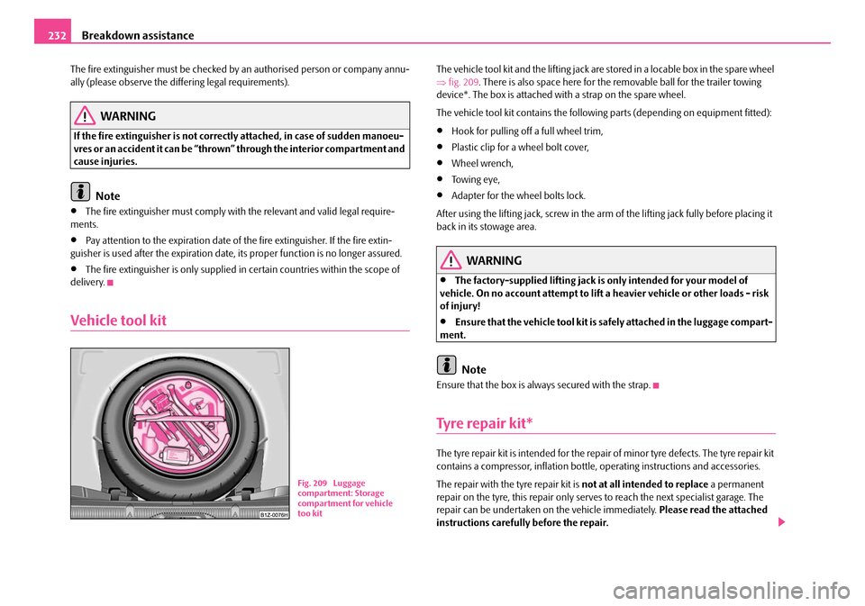
The vehicle tool kit and the li fting jack are stored in a locable box in the spare wheel
⇒ fig. 209 . There is also space here for the removable ball for the trailer towing
device*. The box is attached wi th a strap on the spare wheel.
The vehicle tool kit contains the following parts (depending on equipment fitted):
•Hook for pulling off a full wheel trim,
•Plastic clip for a wheel bolt cover,
•Wheel wrench,
•To w i n g e y e ,
•Adapter for the wheel bolts lock.
After using the lifting jack, screw in the arm of the lifting jack fully before placing it
back in its stowage area.
WARNING
•The factory-supplied lifting jack is only intended for your model of
vehicle. On no account attempt to lift a heavier vehicle or other loads - risk
of injury!
•Ensure that the vehicle tool kit is safely attached in the luggage compart-
ment.
Note
Ensure that the box is alwa ys secured with the strap.
Tyre repair kit*
The tyre repair kit is intended for the repair of minor tyre defects. The tyre repair kit
contains a compressor, inflation bottle, operating instructions and accessories.
The repair with the tyre repair kit is not at all intended to replace a permanent
repair on the tyre, this repair only serves to reach the next specialist garage. The
repair can be undertaken on the vehicle immediately. Please read the attached
instructions carefully before the repair.
Fig. 209 Luggage
compartment: Storage
compartment for vehicle
too kit
NKO A5 20 MR08.book Page 232 Wednesday, April 11, 2007 2:54 PM
Page 235 of 288
Breakdown assistance
234
WARNING
•If you find yourself in flowing traffic switch on the hazard warning lights
system and place the warning triangle on the side of the road at the
prescribed distance from your vehicl e while observing all national legal
provisions. In this way you are protecting not only yourself but also other
road users.
•Never start the engine with the vehicle sitting on the raised jack - danger
of suffering injury!
Caution
If you have to change a wheel on a slope first block the opposite wheel with a stone
or similar object in order to secure th e vehicle from unexpectedly rolling away.
Note
Comply with the national legal regulations.
Changing a wheel
Always change a wheel on a level surface as far as possible.
– Take off the full wheel trim* ⇒page 235 or the caps ⇒page 235.
– In the case of light alloy wheels remove the wheel trim cap ⇒page 236.
– Slacken the wheel bolts ⇒page 236.
– Jack up the vehicle until the wheel to be changed is clear of the ground
⇒ page 237.
– Unscrew the wheel bolts and place them on a clean surface (cloth, paper etc.).
– Take off the wheel. – Fit on the spare wheel and tighten the wheel bolts slightly.
– Lower the car.
– Tighten the wheel bolts firmly, al
ternately and diagonally using the
wheel wrench ⇒page 236.
– Mount the full wheel trim/w heel trim cap or the caps.
Note
•All bolts must be clean and must turn easily.
•You must never grease or oil the wheel bolts!
•When fitting on unidirectional tyres, ensure that the tyres rotate in the correct
direction ⇒page 223.
Subsequent steps
After changing the wheel, you must perform the following steps.
– Stow and attach the replaced wheel in the spare wheel well.
– Stow the vehicle tool kit in the space provided.
– Check the tyre pressure on the spare wheel just mounted as soon as
possible.
– Have the tightening torque of the wheel bolts checked with a torque
wrench as soon as possible. Steel and light alloy wheels must be tight-
ened to a tightening torque of 120 Nm.
– Have the defective tyre repaired as soon as possible.
WARNING
It is necessary to observe the guidelines given on ⇒page 225, “New tyres
and wheels” if the vehicle is subseq uently fitted with tyres which are
different to those it was fitted with at the works.
NKO A5 20 MR08.book Page 234 Wednesday, April 11, 2007 2:54 PM
Page 236 of 288
Breakdown assistance235
Using the systemSafetyDriving TipsGeneral MaintenanceBreakdown assistanceTechnical Data
Note
•If you find, when changing the wheel, that the wheel bolts are corroded and
difficult to turn, the bolts mu st be replaced before checking the tightening torque.
•Drive cautiously and only at a moderate speed to a workshop where the tight-
ening torque can be checked.
Full wheel trim*
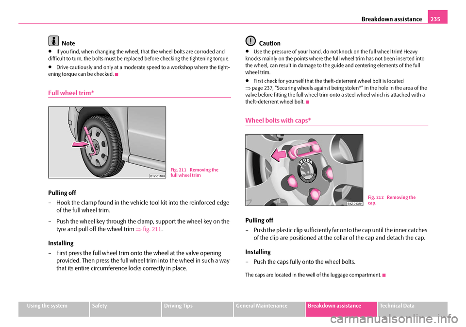
Pulling off
– Hook the clamp found in the vehicle tool kit into the reinforced edge of the full wheel trim.
– Push the wheel key through the clamp, support the wheel key on the tyre and pull off the wheel trim ⇒fig. 211 .
Installing
– First press the full wheel trim onto the wheel at the valve opening provided. Then press the full wheel trim into the wheel in such a way
that its entire circumference locks correctly in place. Caution
•Use the pressure of your hand, do not knock on the full wheel trim! Heavy
knocks mainly on the points where the full wheel trim has not been inserted into
the wheel, can result in damage to the guide and centering elements of the full
wheel trim.
•First check for yourself that the theft-deterrent wheel bolt is located
⇒ page 237, “Securing wheels against being stolen*” in the hole in the area of the
valve before fitting the full wheel trim on to a steel wheel which is attached with a
theft-deterrent wheel bolt.
Wheel bolts with caps*
Pulling off
– Push the plastic clip sufficiently fa r onto the cap until the inner catches
of the clip are positioned at the collar of the cap and detach the cap.
Installing
– Push the caps fully onto the wheel bolts.
The caps are located in the we ll of the luggage compartment.
Fig. 211 Removing the
full wheel trim
Fig. 212 Removing the
cap.
NKO A5 20 MR08.book Page 235 Wednesday, April 11, 2007 2:54 PM
Page 238 of 288

Breakdown assistance237
Using the systemSafetyDriving TipsGeneral MaintenanceBreakdown assistanceTechnical Data
Raise vehicle
You have to raise the vehicle with a lifting jack in order to be able to
take off the wheel.
Position the lifting jack by selecting the jacking point which is closest to
the wheel to be removed ⇒fig. 215 . The jacking point is located directly
below the engraving in the lower sill. The engraving is only visible after
opening the door.
– Position the lifting jack below the jacking point and move it up until its claw is positioned directly below the vertical web of the lower sill.
– Align the car jack so that its claw grasps the web of the lower sill and the base plate is resting flat on the floor.
– Turn the lifting jack up further until the wheel is just clear of the ground.
Ground below the lifting jack which is soft and slippery can cause the vehicle to
slip off the jack. It is therefore always ne cessary to place the lifting jack on a solid
surface or use a wide and stable base. Use a non-slip base (e.g. a rubber foot mat)
if the surface is smooth, such as cobbled stones, a tiled floor, etc.
WARNING
•Always raise the vehicle with the doors closed - risk of injury!
•Take suitable measures to prevent the base of the lifting jack from slip-
ping off - risk of injury!
•Not positioning the lifting jack at the specified points can result in
damage to the vehicle. The jack can also sl ip off if it does not have sufficient
grip - risk of injury!
•It is important to support the vehicle with suitable supporting blocks if
you wish to work under the lifted vehicle - risk of injury!
Securing wheels against being stolen*
You need a special adapter for slackening the safety wheel bolts.
– Pull off the full wheel trim/cap from the wheel hub or cap from the safety wheel bolt.
– Insert the adapter with its toothed side fully into the inner toothing of the safety wheel bolt right down in such a way that only the
outer hexagon is jutting out ⇒fig. 216 .
– Insert the wheel wrench fully onto the adapter .
– Slacken the wheel bolt, or tighten it firmly ⇒page 236.
Fig. 215 Changing a
wheel: Points for posi-
tioning car jack
AA
ABFig. 216 Safety wheel
bolt with adapter
AB
AA
AB
NKO A5 20 MR08.book Page 237 Wednesday, April 11, 2007 2:54 PM