remote control SKODA OCTAVIA 2008 2.G / (1Z) User Guide
[x] Cancel search | Manufacturer: SKODA, Model Year: 2008, Model line: OCTAVIA, Model: SKODA OCTAVIA 2008 2.G / (1Z)Pages: 304, PDF Size: 17.69 MB
Page 56 of 304
Unlocking and locking55
Using the systemSafetyDriving TipsGeneral MaintenanceBreakdown assistanceTechnical Data
The force limiter is only switched off, if you attempt to close the window within the
next 10 seconds -
the window closes now with full strength!
If you wait longer than 10 seconds, the force limiter is switched on again.
WARNING
You should take particular care when closing the windows! You may other-
wi se s uffe r s e ve re i njur ie s a s a re sul t of getting an arm, for example, jammed
in the window!
Window convenience operation
You can open and close the electrically powered windows as follows
when unlocking and locking the vehicle (just closing of the sliding roof).
Opening a window
– Turn the key in the lock of the driver door into the opening position or
press the opening button of the radio remote control until all the
windows are open.
Closing a window
– Turn the key in the lock of the driver door into the closing position or press the closing button of the radio remote control until all the
windows are closed.
You can interrupt the opening or closing operation of the windows immediately by
releasing the key or the closing button.
WARNING
The system is fitted with a force limiter ⇒page 54. The clos ing process will
be stop if an obstruction is detected and the window will open again. You
should then take particular care when closing the windows! You may other- wis e suf fe r se v e re inj uri es a s a re s ult of g e tt ing a n ar m , for e xa m ple , ja m m e d
in the window!
Note
•On vehicles fitted with anti-theft
alarm system the convenience window
opening is possible by means of the key in the lock only 45 seconds after deacti-
vating the warning system or after ac tivating the anti-theft alarm system.
Operational faults
Electrically operated power windows do not operate
If the battery of the car has been disconnected and then reconnected, the electri-
cally operated power windows do not operate. The system must be activated.
Proceed as follows in order to re-establish the function:
•Switch on the ignition.
•Press the relevant switch top and hold it pressed as long as necessary until the
window is closed.
•Release the switch.
•Press once again the relevant switch top and hold it pressed for approx. 3
seconds.
Operation in winter
Ice accumulating on the surface of the wi ndows during the winter may result in a
greater resistance when closing the windows and the window may stop and move
back several centimetres
Proceed as follows to close the window fully:
•Turn the key in the lock of the driver d oor into the closing position and hold it
there until all of the windows are closed.
•repeat this operation until the window stops.
WARNING (continued)
20A5Facelift.book Page 55 Saturday, September 6, 2008 2:13 PM
Page 58 of 304
Unlocking and locking57
Using the systemSafetyDriving TipsGeneral MaintenanceBreakdown assistanceTechnical Data
Closing
Sliding closed/closing the sliding/tilting roof
– Turn the switch to position ⇒page 56, fig. 53 .
Safety closing
The sliding/tilting roof is equipped with an overload protection system. If an
obstacle (e.g. ice) prevents closing, the sliding/tilting roof stops and opens
completely. You can close the sliding/tilting roof completely without overload
protection by pressing the switch to the position ⇒page 56, fig. 53 at the front
for as long as it takes for the sliding/tilting roof to shut completely ⇒.
WARNING
Close the sliding/tilting roof carefully - risk of injury!
Convenience operation
You can also close an open sliding/tilting roof from the outside.
– Turn the key in the lock of the driver door into the closing position or
press the closing button of the remote control until the sliding/tilting
roof is closed ⇒.
The closing process stops when one releases the key or the closing button.
WARNING
Close the sliding/tilting roof carefully - risk of injury! The overload protec-
tion system does not function with the convenience closing.
Emergency operation
You can close and/or open the sliding/tilting roof by hand if the system is
defect.
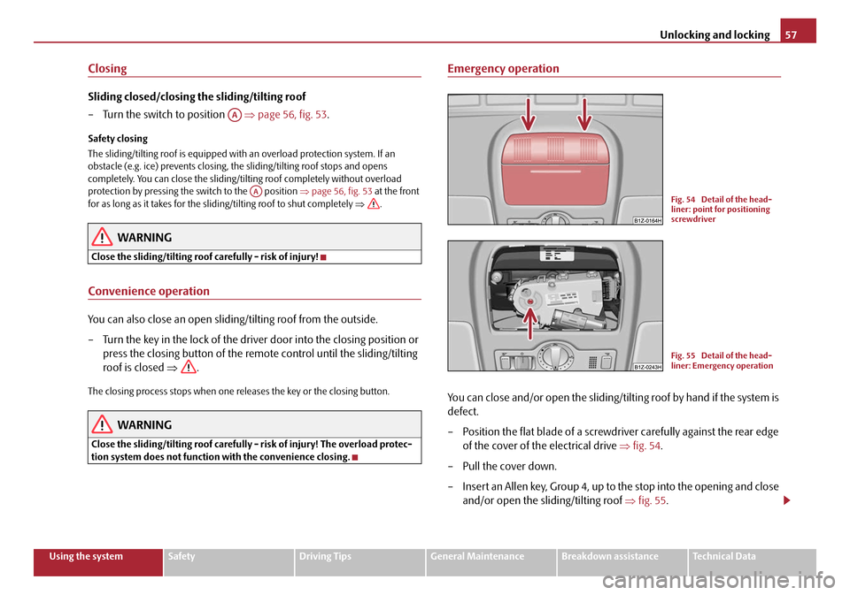
– Position the flat blade of a screwdriver carefully against the rear edge
of the cover of th e electrical drive ⇒fig. 54 .
– Pull the cover down.
– Insert an Allen key, Group 4, up to the stop into the opening and close
and/or open the sliding/tilting roof ⇒fig. 55 .
AA
AAFig. 54 Detail of the head-
liner: point for positioning
screwdriver
Fig. 55 Detail of the head-
liner: Emergency operation
20A5Facelift.book Page 57 Saturday, September 6, 2008 2:13 PM
Page 63 of 304
Lights and Visibility
62
sensor, the Coming Home Func tion is not switched on after switching off the igni-
tion.
Note
•If the Coming Home Function is switch ed on constantly, the battery will be
heavily discharged particularly in short-haul traffic.
•The switching on of the described lights should only be undertaken in accord-
ance with the legal requirements.
•You can change the illumination period for the Coming Home Function by
means of the information display*.
Leaving Home Function
This function makes it possible to switch on the lights when approaching
the vehicle.
Switching on Leaving Home Function
– Unlock the vehicle with the radio remote control - the lights come on.
Depending on equipment fitted the function Leaving Home switches on the
following lights:
•Parking lights,
•Low beam,
•Entry lighting in the exterior mirrors,
•Licence plate light.
Leaving Home Function
The function Leaving Home is controlled wi th the light sensor in the mount of the
interior rear mirror. If the light intensity is higher than the set value of the light
sensor, the Leaving Home Func tion is not switched on after unlocking the vehicle
with the radio remote control. After unlocking the vehicle with the radio remote control, the lights come on for 10
seconds. The Leaving Home Function is also switched off after the ignition is
switched on and after locking the vehicle.
If no door is opened within 30 seconds, th
e lights go out and the vehicle is locked
automatically.
Note
•If the Leaving Home Function is switch ed on constantly, the battery will be
heavily discharged particularly in short-haul traffic.
•The switching on of the described lights should only be undertaken in accord-
ance with the legal requirements.
•You can change the illumination period for the Leaving Home Function by
means of the information display*.
Fog lights*
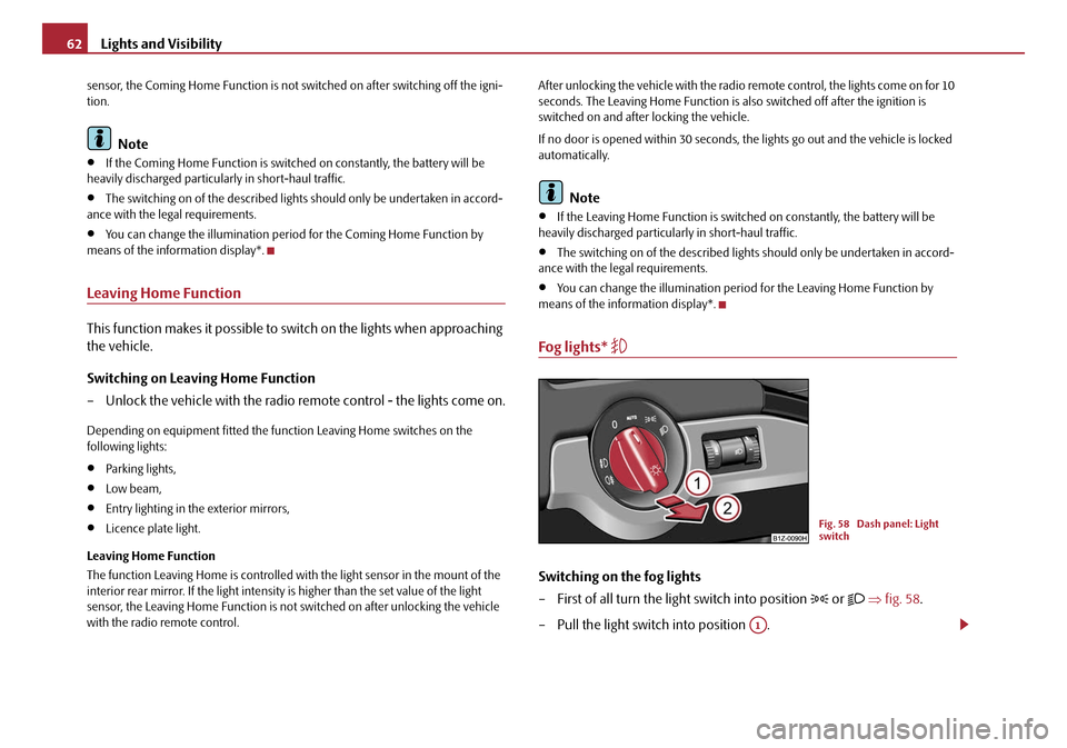
Switching on the fog lights
– First of all turn the light switch into position
or ⇒ fig. 58 .
– Pull the light switch into position .
Fig. 58 Dash panel: Light
switch
A1
20A5Facelift.book Page 62 Saturday, September 6, 2008 2:13 PM
Page 75 of 304
Lights and Visibility
74
Adjusting the right-hand exterior mirror
– Turn the rotary knob to position
. The movement of the mirror
surface is identical to the mo vement of the rotary knob.
Switching off operating control
– Turn the rotary knob to position
.
Folding in both exterior mirrors
– Turn the rotary knob to position
.
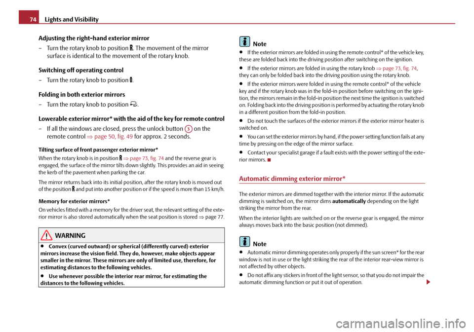
Lowerable exterior mirror* with the aid of the key for remote control
– If all the windows are closed, press the unlock button on the remote control ⇒page 50, fig. 49 for approx. 2 seconds.
Tilting surface of front pa ssenger exterior mirror*
When the rotary knob is in position
⇒ page 73, fig. 74 and the reverse gear is
engaged, the surface of the mirror tilts down slightly. This provides an aid in seeing
the kerb of the pavement when parking the car.
The mirror returns back into its initial po sition, after the rotary knob is moved out
of the position
and put into another position or if the speed is more than 15 km/h.
Memory for exterior mirrors*
On vehicles fitted with a memory for the driver seat, the relevant setting of the exte-
rior mirror is also stored automatically when the seat position is stored ⇒page 77.
WARNING
•Convex (curved outward) or spherical (differently curved) exterior
mirrors increase the vision field. Th ey do, however, make objects appear
smaller in the mirror. These mirrors are only of limited use, therefore, for
estimating distances to the following vehicles.
•Use whenever possible the interior rear mirror, for estimating the
distances to the fo llowing vehicles.
Note
•If the exterior mirrors are folded in using the remote control* of the vehicle key,
these are folded back into the driving po sition after switching on the ignition.
•If the exterior mirrors are folded in using the rotary knob ⇒page 73, fig. 74 ,
they can only be folded back into th e driving position using the rotary knob.
•If the exterior mirrors were folded in using the remote control* of the vehicle
key and if the rotary knob was in the fold -in position before switching on the igni-
tion, the mirrors remain in the fold-in positi on the next time the ignition is switched
on. Folding back into the driving position is performed by actuating the rotary knob
in a different position from the fold-in position.
•Do not touch the surfaces of the exterior mirrors if the exterior mirror heater is
switched on.
•You can set the exterior mirrors by hand, if the power setting function fails at any
time by pressing on the ed ge of the mirror surface.
•Contact your specialist garage if a fault exists with the power setting of the exte-
rior mirrors.
Automatic dimming exterior mirror*
The exterior mirrors are dimmed together with the interior mirror. If the automatic
dimming is switched on, the mirror dims automatically depending on the light
striking the mirror from the rear.
When the interior lights are switched on or the reverse gear is engaged, the mirror
always moves back into the basic position (not dimmed).
Note
•Automatic mirror dimming operates only properly if the sun screen* for the rear
window is not in use or the light striking the rear of the interior rear-view mirror is
not affected by other objects.
•Do not affix any stickers in front of the li ght sensor, so that you do not impair the
automatic dimming function or put it out of operation.
A3
20A5Facelift.book Page 74 Saturday, September 6, 2008 2:13 PM
Page 80 of 304
Seats and Stowage79
Using the systemSafetyDriving TipsGeneral MaintenanceBreakdown assistanceTechnical Data
– Engage reverse gear.
– Move the right exterior mirror into the desired position ⇒page 73.
– Take the vehicle out of gear. The set position of the exterior mirror is stored.
Memory buttons
Memory for the seat offers the possibility to store the individual driver seat and
external mirror position. An individual posi tion can be allocated to each of the three
memory buttons ⇒page 78, fig. 78 , that is three in tota l. After pressing the
corresponding memory button , the seat and the exterior mirror are automati-
cally moved into the positions which have been allocated to this button ⇒page 79.
Emergency Off
You can interrupt the setting operation at any time, if you operate any button of the
driver seat.
Note
•When storing settings with the memory buttons, we recommend that you begin
with the front button and assign a memo ry button to each additional driver.
•Each new setting stored with the same button erases the previous setting.
•Each time you store the seat and exterior mirror settings for driving forward you
also have to re-store the individual setting of the exterior mirror on the passenger
side for reversing.
Assigning remote control to the memory buttons
After storing the settings of the seat and exterior mirrors, you have 10
seconds in order to assign the remote control to the appropriate memory
button.
– Withdraw the ignition key.
– Press the button for unlocking the vehicle ⇒page 50. The setting is
stored with the memory button which you have selected.
If you wish to be able to retrieve the settings which are stored in the memory by also
using the remote control, you have to assign the remote control to a memory
button in each case.
If you wish, you can obtain an additional key with radio remote control from a
Škoda dealer and then assign the radio re mote control to another memory button.
Note
•If the remote control had previously been assigned to another memory button,
this setting is then erased by the new assignment.
•If you assign the remote control to a memory button which has already been
assigned to a remote control, the old assi gnment is also replaced by a new assign-
ment in this case.
•The assignment of the remote control to a memory button is retained, however,
after reassigning the seats and exterior mirrors.
Retrieving settings of the seat and mirrors
You can retrieve the stored settings either with the memory buttons
or with the remote control*.
Retrieving settings with memory buttons
– In order to retrieve the stored setting, you have two possibilities:
– One-touch automatic memory: Briefly press the desired memory
button ⇒page 78, fig. 78 . The seat and exterior mirror are moved
automatically into the stored position s (this applies only if the ignition
is switched on and the speed is less than 5 km/h).
– Memory keying : Press and hold the desired memory button
pressed long enough until the seat and the exterior mirror are moved
into the stored positions.
ABAB
AB
AB
20A5Facelift.book Page 79 Saturday, September 6, 2008 2:13 PM
Page 81 of 304
Seats and Stowage
80
Retrieving settings with remote control
– If the driver door is clos ed and the ignition is switched off, briefly press
the unlock button of the remote control ⇒page 50 and then open the
driver door.
– The seat and exterior mirrors now move automatically into the stored positions.
Retrieving setting of exterior mirror for reversing*
– Turn the rotary knob for the exterior mirror setting into the position
⇒ page 73 before engaging the reverse gear.
The mirror returns back into its initial po sition, after the rotary knob is moved out
of the position and put into another position or if the speed is more than 15 km/h.
Emergency Off
You can interrupt the setting operation at an y time, if you operate any button of the
driver seat.
Head restraints
Best protection is achieved if the top edge of the head restraint is at the
same level as the upper part of your head.
Adjusting the height of a head restraint
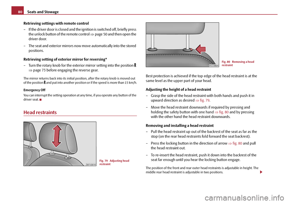
– Grasp the side of the head restraint with both hands and push it in upward direction as desired ⇒fig. 79 .
– Move the head restraint downwards if required by pressing and holding the safety button with one hand ⇒fig. 80 and by pressing
with the other hand the head restraint downwards.
Removing and installing a head restraint
– Pull the head restraint up out of the backrest of the seat as far as the stop (on the rear head restraints fold forward the seat backrest).
– Press the locking button in the direction of arrow ⇒fig. 80 and pull
the head restraint out.
– To re-insert the head restraint, push it down into the backrest of the seat far enough until you hear the locking button engage.
The position of the front and rear outer head restraints is adjustable in height. The
middle rear head restraint is adjustable in two positions.
Fig. 79 Adjusting head
restraint
Fig. 80 Removing a head
restraint
20A5Facelift.book Page 80 Saturday, September 6, 2008 2:13 PM
Page 122 of 304
Heating and air conditioning system121
Using the systemSafetyDriving TipsGeneral MaintenanceBreakdown assistanceTechnical Data
– Return to a higher level by selecting the menu point Back, i. e. in the
menu Aux. Heating (auxiliary heating) .
– In the menu Aux. Heating (auxiliary heating) select the menu point
Running time and set the desired operating period in steps of
1 minute. The operating period can be 5 to 60 minutes.
– By selecting the menu point Back, you will reach in the menu
Aux. Heating (auxiliary heating) .
– In the menu Aux. heating (auxiliary heating) select the menu point
Mode .
– In the menu Mode select the desired mode Heating or Ventilation .
Programming
For the programming of the auxiliary heating (auxiliary heating and ventilation) in
the menu Aux. heating (Aux. heating) there are three pre-set times:
•Pre-set time 1
•Pre-set time 2
•Pre-set time 3
In each pre-set time, the day (if necessary each day = daily) and the time (hour and
minute) can be set for the operating period of the auxiliary heating and/or ventila-
tion.
If you leave the pre-set menu by selecting the menu Back or do not operate the
display for longer than 10°seconds, the set values are stored, but the pre-set time is
not active.
Both other pre-set times can be prog rammed and stored in the same way.
If you select the menu Activate after setting the desired values, appears on the
display Pre-set time (weekday, hours, minute) activated! and the set pre-set
time is active.
Only one programmed pre-set time can be active.
The last programmed pre-set time remains active. Changing the active pre-set time is carried out after selecting the menu point
Activate
in the menu Aux. heating (auxiliary heating) by selecting a pre-set time.
The prerequisite for the correct switching on of the auxiliary heating (auxiliary
heating and ventilation) according to th e programmed pre-set time is the correct
setting of the current time and the weekday ⇒ page 120.
If the system is running, a warning light in the button for direct switching on/off of
the auxiliary heating lights up.
The running system deactivates after expiration of the operating period or is deac-
tivated earlier by pres sing the button for direct switching on/off of the auxiliary
heating ⇒page 123.
The random pre-set time can be deactivated by selecting the menu point Deactive
in the menu Activate.
After selecting the menu point Fa c t o r y s e t t i n g in the menu Aux. heating
(auxiliary heating) , it is possible to change to the factory setting.
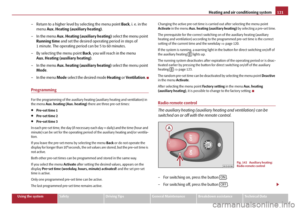
Radio remote control
The auxiliary heating (auxiliary heating and ventilation) can be
switched on or off with the remote control.
– For switching on, press the button .
– For switching off, press the button .
Fig. 142 Auxiliary heating:
Radio remote control
ON
OFF
20A5Facelift.book Page 121 Saturday, September 6, 2008 2:13 PM
Page 123 of 304

Heating and air conditioning system
122
The transmitter and the battery are housed in the housing of the remote control.
The receiver is located in the interior of the car.
If the battery is properly charged, the ef fective range is up to 600 m. For switching
on or off the auxiliary heating, hold the remote control vertically with the antenna
⇒ page 121, fig. 142 towards the top. You must not cover over the antenna with
the fingers or the palm of the hand. Obstacles between the remote control and the
vehicle, bad weather conditio ns and a weaker battery can clearly reduce the range.
The auxiliary heating can only be switched on or off with the remote control, if the
distance between the remote control and the vehicle is at least 2 m.
Warning light in the remote control
The warning light in the remote control ⇒page 121, fig. 142 indicates after a
keystroke if the remote control signal was received by the auxiliary heating and if
the battery is adequately charged.Caution
There are electronic components in the remote control, protect the remote control
against water, severe shoc ks and direct sun rays.
Changing the battery of the radio remote control
If the warning light of the remote control indicates a weak or discharged
battery, ⇒page 121, fig. 142 , it must be replaced. The battery is located
under a cover on the back of the remote control.
– Place a coin into the gap of the battry cover and by turning to the left, unlock the cover.
– Change the battery, insert the cover and lock it by turning to the right.
For the sake of the environment
Dispose of an old battery in accord ance with environmental regulations.
Note
•Pay attention to the correct polarity when changing the battery.
•The replacement battery must have the same specification as the original
battery.
Display warning lightImportance
Lights up green for 2 seconds.The auxiliary heating was switched on.
Lights up red for 2 seconds.The auxiliary heating was switched off.
Slowly flashes green for 2 seconds.The ignition signal was not received.
Quickly flashes green for 2 seconds.The auxiliary heating is blocked, e. g
because the tank is nearly empty or
there is a fault in the auxiliary heating.
Flashes red for 2 seconds.The switch off signal was not received.
Lights up orange for 2 seconds, then
green or red.The battery is weak, however the
switching on or off signal was received.
Lights up orange for 2 seconds, then
flashes green or red.The battery is weak, however the
switching on or off signal was not
received.
Flashes orange for 5 seconds.The battery is discharged, however the
switching on or off signal was not
received.
AA
20A5Facelift.book Page 122 Saturday, September 6, 2008 2:13 PM
Page 153 of 304
Communication
152
Example for erasing individual names out of the phone phonebook
As long as the phonebook is read out, ot her entries can be erased by pressing the
PTT button.
You can end the dialogue at an y time with the voice command CANCEL.
Listening-in to the phonebook
– Press the PTT button.
– Give the command LISTEN TO/PLAY PHONEBOOK after the signal
tone.
After giving this command th e phone voice phone book is read out by the system.
By pressing the PTT button when announcin g the desired name, the corresponding
telephone number is being dialed; the system answers: “ The number is being
dialed ”.
Universal telephone preinstallation GSM III*
Introduction
This enables you to make full use of the advantages of a normal carphone (“hands-
free system” using a microphone integrated in the vehicle, optimal transmission of
signals using an external aerial etc.). The equipment includes also the voice control.
The telephone is connected using the rSAP profile - Remote SIM access profile
(telecommunication of the SIM data) by means of Bluetooth
® technology, if your
telephone supports this profile. The equi pment includes the following functions:
•Display of the SMS text in the information display.
•Free talking in the vehicle interior.
•MUTE signal to the radio.
•Voice control (with the set-up possibility for “short and long dialogue”,
depending on the user's knowledge of the operating structure).
•Convenience mode with the multifunction steering wheel and the display in the
information display.
•Handsfree-system.
The voice control of the telephone is activated by pressing the button PTT on the
multifunction steering wheel ⇒page 155, fig. 164 .
A phone phonebook is part of the univers al telephone preinstallation GSM III with
voice control. In the phone phonebook there are 1000 free memory locations avail-
able. This phone phonebook is independen t of the appliance used for the mobile
phone.
Furthermore the volume can be changed individually at any time with the button
for setting the radio* or on vehicles fitte d with multifunction steering wheel* with
function buttons on the steering wheel.
Dialogue
The period, in which the telephone system is ready to receive voice commands and
carry out the voice commands, is called DIALOGUE. The system gives audible feed-
back and guides you if necessary through the relevant functions. You can start or
end the dialogue at any time by pressing the PTT button.
Voice commandAnnouncement
DELETE PHONEBOOK“ Do you want to delete the whole
phonebook? ”
If no entry is put in, the following a nnouncement is made after about 5 seconds.
“Possible commands are: yes, no,
repeat ”.
NOThe phonebook is read out.
When announcing the entry to be
erased, press the PTT button.“Do you want to delete (name)? ”
If no entry is put in, the following a nnouncement is made after about 5 seconds.
“Possible commands are: yes, no ”.
YES“The name is deleted ”.
Continue reading out the phone book.
20A5Facelift.book Page 152 Saturday, September 6, 2008 2:13 PM
Page 299 of 304
Index
298
Jump-starting . . . . . . . . . . . . . . . . . . . . . . . . . . . 252, 253
K
Key . . . . . . . . . . . . . . . . . . . . . . . . . . . . . . . . . . . . . . . . . . 42
L
Lashing eyes . . . . . . . . . . . . . . . . . . . . . . . . . . . . . . . . . 86
Leather care . . . . . . . . . . . . . . . . . . . . . . . . . . . . . . . . . 216
Light
automatic . . . . . . . . . . . . . . . . . . . . . . . . . . . . . . . . 60
Changing bulbs . . . . . . . . . . . . . . . . . . . . . . . . . . 262
Light bulbs Warning light . . . . . . . . . . . . . . . . . . . . . . . . . . . . . 34
Lights converting/masking over . . . . . . . . . . . . . . . . . 206
Range adjustment . . . . . . . . . . . . . . . . . . . . . . . . . 64
switching on and off . . . . . . . . . . . . . . . . . . . . . . . 59
Warning lights . . . . . . . . . . . . . . . . . . . . . . . . . . . . 32
Lights and Visibility . . . . . . . . . . . . . . . . . . . . . . . . . . . 64
Liquid in reservoir for windscreen washer system Warning light . . . . . . . . . . . . . . . . . . . . . . . . . . . . . 40
Loading . . . . . . . . . . . . . . . . . . . . . . . . . . . . . . . . . . . . . . 85
Lock Central locking system . . . . . . . . . . . . . . . . . . . . . 47
lock Central locking system . . . . . . . . . . . . . . . . . . . . . 46
Locking . . . . . . . . . . . . . . . . . . . . . . . . . . . . . . . . . . . . . . 45 Remote control . . . . . . . . . . . . . . . . . . . . . . . . . . . 50
Locking and unlocking from inside . . . . . . . . . . . . . 47
Low beam . . . . . . . . . . . . . . . . . . . . . . . . . . . . . . . . . . . 59 Warning light . . . . . . . . . . . . . . . . . . . . . . . . . . . . . 34 Lugagge . . . . . . . . . . . . . . . . . . . . . . . . . . . . . . . . . . . . . . 48
Luggage compartment . . . . . . . . . . . . . . . . . . . . . 48, 85
Folding double hooks . . . . . . . . . . . . . . . . . . . . . . 86
Folding hooks . . . . . . . . . . . . . . . . . . . . . . . . . . . . . 87
Lashing eyes . . . . . . . . . . . . . . . . . . . . . . . . . . . . . . 86
Luggage compartment door Lighting . . . . . . . . . . . . . . . . . . . . . . . . . . . . . . . . . . . 67
Luggage rack . . . . . . . . . . . . . . . . . . . . . . . . . . . . . . . . . . 93
M
Main beam . . . . . . . . . . . . . . . . . . . . . . . . . . . . . . . 59, 65 Warning light . . . . . . . . . . . . . . . . . . . . . . . . . . . . . . 34
Manual gearbox . . . . . . . . . . . . . . . . . . . . . . . . . . . . . 127
Manual shifting of gears . . . . . . . . . . . . . . . . . . . . . 127
Memory for the on-board computer . . . . . . . . . . . . 21
Mobile phone . . . . . . . . . . . . . . . . . . . . . . . . . . . 143, 160 Bluetooth . . . . . . . . . . . . . . . . . . . . . . . . . . . 144, 152
Motoring abroad . . . . . . . . . . . . . . . . . . . . . . . . . . . . 206
Multifunction steering wheel . . . . . . . . . . . . . . . . . 141
Multi-functional indicator . . . . . . . . . . . . . . . . . . . . . . 21
N
Navigation system . . . . . . . . . . . . . . . . . . . . . . . . . . . . . 28
Note holder . . . . . . . . . . . . . . . . . . . . . . . . . . . . . . . . . . . 95
O
Oil . . . . . . . . . . . . . . . . . . . . . . . . . . . . . . . . . . . . . . . . . 227 Warning light . . . . . . . . . . . . . . . . . . . . . . . . . . . . . . 36
Oil dipstick . . . . . . . . . . . . . . . . . . . . . . . . . . . . . . . . . 227
Onboard computer . . . . . . . . . . . . . . . . . . . . . . . . . . . . 21 Open door
Warning light . . . . . . . . . . . . . . . . . . . . . . . . . . . . . 40
Opening a single door . . . . . . . . . . . . . . . . . . . . . . . . . 45
Opening for skis . . . . . . . . . . . . . . . . . . . . . . . . . . . . . 104
Operation in winter Battery . . . . . . . . . . . . . . . . . . . . . . . . . . . . . . . . . . 234
Biodiesel . . . . . . . . . . . . . . . . . . . . . . . . . . . . . . . . 221
De-icing windows . . . . . . . . . . . . . . . . . . . . . . . . 214
Outside temperature . . . . . . . . . . . . . . . . . . . . . . . . . . 23
Overview of the engine compartment . . . . . . . . . 226
P
Paint . . . . . . . . . . . . . . . . . . . . . . . . . . . . . . . . . . . . . . . . 213
Paint damage . . . . . . . . . . . . . . . . . . . . . . . . . . . . . . . . 213
Parking . . . . . . . . . . . . . . . . . . . . . . . . . . . . . . . . . . . . . . 129
Parking aid rear . . . . . . . . . . . . . . . . . . . . . . . . . . . . . . . . . . . . . 129
parking aid Front and rear . . . . . . . . . . . . . . . . . . . . . . . . . . . . 130
Parking light . . . . . . . . . . . . . . . . . . . . . . . . . . . . . . . . . . 65
Parking the vehicle . . . . . . . . . . . . . . . . . . . . . . . . . . . 129
Passive Safety . . . . . . . . . . . . . . . . . . . . . . . . . . . . . . . 163
Pedals . . . . . . . . . . . . . . . . . . . . . . . . . . . . . . . . . . . . . . . 85
Petrol . . . . . . . . . . . . . . . . . . . . . . . . . . . . . . . . . . . . . . . 219
Petrol engines Starting the engine . . . . . . . . . . . . . . . . . . . . . . . 126
Polishing . . . . . . . . . . . . . . . . . . . . . . . . . . . . . . . . . . . . 213
Power steering . . . . . . . . . . . . . . . . . . . . . . . . . . . . . . 198 Warning light . . . . . . . . . . . . . . . . . . . . . . . . . . . . . 35
Power window . . . . . . . . . . . . . . . . . . . . . . . . . . . . . . . 53
20A5Facelift.book Page 298 Saturday, September 6, 2008 2:13 PM