Outlet SKODA OCTAVIA 2008 2.G / (1Z) Owner's Manual
[x] Cancel search | Manufacturer: SKODA, Model Year: 2008, Model line: OCTAVIA, Model: SKODA OCTAVIA 2008 2.G / (1Z)Pages: 304, PDF Size: 17.69 MB
Page 4 of 304
Contents3
Using the systemSafetyDriving TipsGeneral MaintenanceBreakdown assistanceTechnical Data
Contents
Layout of this Owner's Manual
(explanations)
. . . . . . . . . . . . . . . . . . . . . . . . . .
Using the system. . . . . . . . . . . . . . . . . . . . . .
Cockpit. . . . . . . . . . . . . . . . . . . . . . . . . . . . . . . . . . . . . . . .
Overview . . . . . . . . . . . . . . . . . . . . . . . . . . . . . . . . . . . .
The brief instruction . . . . . . . . . . . . . . . . . . . . . . . . . .
Basic functions and important information . . . . .
Instruments and Indicator/Warning Lights. . .
General view of the instrument cluster . . . . . . . . .
Engine revolutions counter . . . . . . . . . . . . . . . . . . . .
Speedometer . . . . . . . . . . . . . . . . . . . . . . . . . . . . . . . .
Coolant temperature gauge . . . . . . . . . . . . . . . . . . .
Fuel gauge . . . . . . . . . . . . . . . . . . . . . . . . . . . . . . . . . . .
Counter for distance driven . . . . . . . . . . . . . . . . . . .
Service Interval Display . . . . . . . . . . . . . . . . . . . . . . .
Digital clock . . . . . . . . . . . . . . . . . . . . . . . . . . . . . . . . . .
Multi-functional indicato r (onboard computer)*
Information display* . . . . . . . . . . . . . . . . . . . . . . . . . .
Audio . . . . . . . . . . . . . . . . . . . . . . . . . . . . . . . . . . . . . . . .
Navigation system* . . . . . . . . . . . . . . . . . . . . . . . . . . .
Auto Check Control* . . . . . . . . . . . . . . . . . . . . . . . . . .
Warning lights . . . . . . . . . . . . . . . . . . . . . . . . . . . . . . . .
Unlocking and locking . . . . . . . . . . . . . . . . . . . . . . . .
Key . . . . . . . . . . . . . . . . . . . . . . . . . . . . . . . . . . . . . . . . . .
Key with light* . . . . . . . . . . . . . . . . . . . . . . . . . . . . . . . .
Changing the battery of the radio remote control
Electronic immobiliser . . . . . . . . . . . . . . . . . . . . . . . .
Child safety lock . . . . . . . . . . . . . . . . . . . . . . . . . . . . . .
Central locking system . . . . . . . . . . . . . . . . . . . . . . . .
Remote control* . . . . . . . . . . . . . . . . . . . . . . . . . . . . . . Synchonisation of the remote control . . . . . . . . . .
Anti-theft alarm system* . . . . . . . . . . . . . . . . . . . . . .
Power windows* . . . . . . . . . . . . . . . . . . . . . . . . . . . . .
Electric sliding/tilting roof* . . . . . . . . . . . . . . . . . . . .
Lights and Visibility . . . . . . . . . . . . . . . . . . . . . . . . . . .
Lights . . . . . . . . . . . . . . . . . . . . . . . . . . . . . . . . . . . . . . . .
Interior lighting . . . . . . . . . . . . . . . . . . . . . . . . . . . . . . .
Visibility . . . . . . . . . . . . . . . . . . . . . . . . . . . . . . . . . . . . .
Windshield wiper and wash system . . . . . . . . . . . .
Rear-view mirror . . . . . . . . . . . . . . . . . . . . . . . . . . . . .
Seats and Stowage. . . . . . . . . . . . . . . . . . . . . . . . . . . .
Front seats . . . . . . . . . . . . . . . . . . . . . . . . . . . . . . . . . . .
Adjusting front seats electrically* . . . . . . . . . . . . . .
Head restraints . . . . . . . . . . . . . . . . . . . . . . . . . . . . . . .
Middle rear head restraint* . . . . . . . . . . . . . . . . . . . .
Rear seats . . . . . . . . . . . . . . . . . . . . . . . . . . . . . . . . . . . .
Pedals . . . . . . . . . . . . . . . . . . . . . . . . . . . . . . . . . . . . . . .
luggage compartment . . . . . . . . . . . . . . . . . . . . . . . .
Net partition (Estate)* . . . . . . . . . . . . . . . . . . . . . . . .
The roof rack* . . . . . . . . . . . . . . . . . . . . . . . . . . . . . . . .
Cup holder . . . . . . . . . . . . . . . . . . . . . . . . . . . . . . . . . . .
Note holder . . . . . . . . . . . . . . . . . . . . . . . . . . . . . . . . . .
Ashtray* . . . . . . . . . . . . . . . . . . . . . . . . . . . . . . . . . . . . .
Cigarette lighter*, power sockets . . . . . . . . . . . . . . .
Storage compartments . . . . . . . . . . . . . . . . . . . . . . . .
Overview . . . . . . . . . . . . . . . . . . . . . . . . . . . . . . . . . . . .
Storage compartment on the front passenger side
Cooling of storage compartment on front
passenger side* . . . . . . . . . . . . . . . . . . . . . . . . . . . . . .
Storage compartment on the driver's side . . . . . .
Storage compartment on the dash panel* . . . . . .
Stowage compartment in front centre console* .
Storage net on the front centre console* . . . . . . . Stowage compartment for spectacles* . . . . . . . . .
Storage compartment in the front doors . . . . . . .
Stowage compartment below front passenger
seat* . . . . . . . . . . . . . . . . . . . . . . . . . . . . . . . . . . . . . . . .
Front seat armrest with storage compartment* .
Rear seat armrest with storage compartment* . .
Stowage compartment in rear centre console* .
Seat backrest with opening for skis* . . . . . . . . . . . .
Through-loading bag* . . . . . . . . . . . . . . . . . . . . . . . .
Side compartment* . . . . . . . . . . . . . . . . . . . . . . . . . .
Stowage compartment behind the rear seats
(estate car) . . . . . . . . . . . . . . . . . . . . . . . . . . . . . . . . . . .
Clothes hooks* . . . . . . . . . . . . . . . . . . . . . . . . . . . . . .
Heating and air conditioning system. . . . . . . . .
Air outlet vents . . . . . . . . . . . . . . . . . . . . . . . . . . . . . . .
Heating . . . . . . . . . . . . . . . . . . . . . . . . . . . . . . . . . . . . . .
Climatic* (semi-automatic air conditioning
system) . . . . . . . . . . . . . . . . . . . . . . . . . . . . . . . . . . . . . .
Climatronic* (automatic air conditioning) . . . . . .
Auxiliary heating (auxiliary heating and
ventilation)* . . . . . . . . . . . . . . . . . . . . . . . . . . . . . . . . .
Starting-off and Driving . . . . . . . . . . . . . . . . . . . . . .
Setting steering wheel position . . . . . . . . . . . . . . . .
Ignition lock . . . . . . . . . . . . . . . . . . . . . . . . . . . . . . . . .
Starting the engine . . . . . . . . . . . . . . . . . . . . . . . . . . .
Switching off the engine . . . . . . . . . . . . . . . . . . . . . .
Shifting (manual gearbox) . . . . . . . . . . . . . . . . . . . . .
Handbrake . . . . . . . . . . . . . . . . . . . . . . . . . . . . . . . . . . .
Rear parking aid* . . . . . . . . . . . . . . . . . . . . . . . . . . . . .
Front and rear parking aid* . . . . . . . . . . . . . . . . . . . .
Cruise control system (CCS)* . . . . . . . . . . . . . . . . . .
Automatic gearbox . . . . . . . . . . . . . . . . . . . . . . . . . . .
Automatic gearbox* . . . . . . . . . . . . . . . . . . . . . . . . . .
6
7
9
9
11
11
17
17
18
18
18
18
19
20
21
21
26
28
28
28
32
42
42
42
43
44
44
45
49 51
51
53
56
59
59
66
67
69
73
76
76
77
80
81
81
85
85
91
93
94
95
95
97
98
98
99
99
100
100
101
101 101
102
102
102
103
104
104
105
106
106
107
108
108
109
111
115
119
124
124
125
126
127
127
128
129
130
131
134
134
20A5Facelift.book Page 3 Saturday, September 6, 2008 2:13 PM
Page 10 of 304
Cockpit9
Using the systemSafetyDriving TipsGeneral MaintenanceBreakdown assistanceTechnical Data
Cockpit
Overview
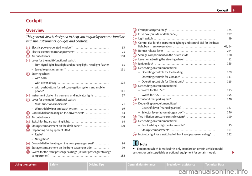
This general view is designed to help you to quickly become familiar
with the instruments, gauges and controls.
Electric power-operated window* . . . . . . . . . . . . . . . . . . . . . . . . . . .
Electric exterior mirror adjustment* . . . . . . . . . . . . . . . . . . . . . . . . .
Air outlet vents . . . . . . . . . . . . . . . . . . . . . . . . . . . . . . . . . . . . . . . . . . . . .
Lever for the multi-functional switch:
−Turn signal light, headlight and parking light, headlight flasher
− Speed regulating system* . . . . . . . . . . . . . . . . . . . . . . . . . . . . . . . .
Steering wheel:
− with horn
− with driver airbag . . . . . . . . . . . . . . . . . . . . . . . . . . . . . . . . . . . . . . . .
− with pushbuttons for radio, na vigation system and mobile
phone* . . . . . . . . . . . . . . . . . . . . . . . . . . . . . . . . . . . . . . . . . . . . . . . . .
Instrument cluster: Instrum ents and indicator lights . . . . . . . . . . .
Lever for the multi-functional switch:
− Multi-functional indicator* . . . . . . . . . . . . . . . . . . . . . . . . . . . . . . .
− Windshield wiper and wash system . . . . . . . . . . . . . . . . . . . . . . .
Control dial for heating on the driver's seat* . . . . . . . . . . . . . . . . . .
Air outlet vents . . . . . . . . . . . . . . . . . . . . . . . . . . . . . . . . . . . . . . . . . . . . .
Switch for hazard warning lights . . . . . . . . . . . . . . . . . . . . . . . . . . . . .
Storage compartment on the dash panel* . . . . . . . . . . . . . . . . . . . .
Depending on equipment fitted:
− Radio*
− Navigation*
Control dial for heating on the front passenger seat* . . . . . . . . . .
Storage compartment on the front passenger side . . . . . . . . . . . .
Switch for the front passenger airbag* (in front passenger stowage
compartment) . . . . . . . . . . . . . . . . . . . . . . . . . . . . . . . . . . . . . . . . . . . . . Front passenger airbag* . . . . . . . . . . . . . . . . . . . . . . . . . . . . . . . . . . . .
Fuse box (on side of dash panel) . . . . . . . . . . . . . . . . . . . . . . . . . . . .
Light switch . . . . . . . . . . . . . . . . . . . . . . . . . . . . . . . . . . . . . . . . . . . . . . . .
Control dial for the instrument lighting and control dial for the head-
light beam range regulation . . . . . . . . . . . . . . . . . . . . . . . . . . . . . . . . .
Bonnet release lever . . . . . . . . . . . . . . . . . . . . . . . . . . . . . . . . . . . . . . .
Storage compartment on the driver's side . . . . . . . . . . . . . . . . . . . .
Lever for adjusting the steering wheel . . . . . . . . . . . . . . . . . . . . . . .
Ignition lock . . . . . . . . . . . . . . . . . . . . . . . . . . . . . . . . . . . . . . . . . . . . . . .
Depending on equipment fitted:
−
Operating controls for the heating . . . . . . . . . . . . . . . . . . . . . . . .
− Operating controls for Climatic* . . . . . . . . . . . . . . . . . . . . . . . . . .
− Operating controls for Climatronic* . . . . . . . . . . . . . . . . . . . . . . .
Depending on equipment fitted:
− Switch for the ESP* . . . . . . . . . . . . . . . . . . . . . . . . . . . . . . . . . . . . . .
− Switch for TCS . . . . . . . . . . . . . . . . . . . . . . . . . . . . . . . . . . . . . . . . . . .
Front and rear parking aid* . . . . . . . . . . . . . . . . . . . . . . . . . . . . . . . . .
Depending on equipment fitted:
− Gearshift lever (manual gearbox) . . . . . . . . . . . . . . . . . . . . . . . . .
− Selector lever (automatic gearbox*) . . . . . . . . . . . . . . . . . . . . . . .
Tyre inflation pressure-control system* . . . . . . . . . . . . . . . . . . . . . .
Depending on equipment fitted:
− Front ashtray - high centre console* . . . . . . . . . . . . . . . . . . . . . .
− Storage compartment* . . . . . . . . . . . . . . . . . . . . . . . . . . . . . . . . . .
Indicator light for a switched off front seat passenger airbag* . .
Note
•Equipment which is marked * is only standard on certain vehicle model
versions or only suppliable as op tional equipment for certain models.
A153
A273
A3108
A4
65
131
A5
175
141
A617
A7
21
69
A884
A9108
A1064
A11100
A12
A1384
A1499
A15182
A16175
A17257
A1859
A1963, 64
A20224
A21100
A2211
A23125
A24
109
111
115
A25
193
195
A26130
A27
127
136
A28199
A29
95
101
A30182
20A5Facelift.book Page 9 Saturday, September 6, 2008 2:13 PM
Page 60 of 304
Lights and Visibility59
Using the systemSafetyDriving TipsGeneral MaintenanceBreakdown assistanceTechnical Data
Lights and Visibility
Lights
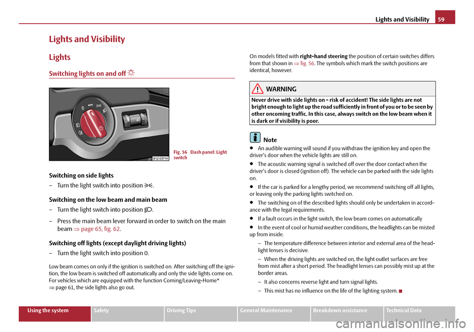
Switching lights on and off
Switching on side lights
– Turn the light switch into position
.
Switching on the low beam and main beam
– Turn the light switch into position
.
– Press the main beam lever forward in order to switch on the main beam ⇒page 65, fig. 62 .
Switching off lights (except daylight driving lights)
– Turn the light switch into position 0.
Low beam comes on only if the ignition is switched on. After switching off the igni-
tion, the low beam is switched off automati cally and only the side lights come on.
For vehicles which are equipped with the function Coming/Leaving-Home*
⇒ page 61, the side lights also go out. On models fitted with
right-hand steering the position of certain switches differs
from that shown in ⇒ fig. 56. The symbols which mark the switch positions are
identical, however.
WARNING
Never drive with side lights on - risk of accident! The side lights are not
bright enough to light up the road suffic iently in front of you or to be seen by
other oncoming traffic. In this case, always switch on the low beam when it
is dark or if visibility is poor.
Note
•An audible warning will sound if you wi thdraw the ignition key and open the
driver's door when the vehicle lights are still on.
•The acoustic warning signal is switched off over the door contact when the
driver's door is closed (ignition off). The vehicle can be parked with the side lights
on.
•If the car is parked for a lengthy period , we recommend switching off all lights,
or leaving only the parking lights switched on.
•The switching on of the described lights should only be undertaken in accord-
ance with the legal requirements.
•If a fault occurs in the light switch , the low beam comes on automatically
•In the event of cool or humid weather co nditions, the headlights can be misted
up from inside.
−The temperature difference between interior and external area of the head-
light lenses is decisive.
− When the driving lights are switched on , the light outlet surfaces are free
from mist after a short period. The headlight lenses can possibly mist up at the
border areas.
− It also concerns reverse light and turn signal lights.
− This mist has no influence on th e life of the lighting system.
Fig. 56 Dash panel: Light
switch
20A5Facelift.book Page 59 Saturday, September 6, 2008 2:13 PM
Page 104 of 304
Seats and Stowage103
Using the systemSafetyDriving TipsGeneral MaintenanceBreakdown assistanceTechnical Data
The armrest is adjustable for height and length.
Opening stowage compartment
– Open the lid of the armrest in the direction of arrow ⇒page 102,
fig. 125 .
Closing stowage compartment
– Open the lid up to the stop, then you can fold it downwards.
Setting height
– First of all fold the lid to the bottom and lift it in the direction of arrow into one of the 4 fixed positions.
Adjusting in forward/back direction
– Push the lid into the desired position.
Opening air inlet
– Pull the lock in upward direction ⇒fig. 126 .
Closing air inlet
– Push the lock as far as the stop downwards.
On vehicles fitted with air conditioning, the storage compartment is equipped with
a lockable inlet for thermally treated (warmed-up) air.
At open air supply, air flows into the storage with a temperature which is as high as
the one out of the air outlet nozzles, depending on temperature setting.
The air inlet in the storage compar tment is connected to position
through
adjustment of the control dial for air distribution. This position causes the
maximum amount of air to flow into th e storage compartment (depending on the
rotary regulator position for the fan).
You can use the storage compartment, for example, to temper drinks cans, etc.
If you do not use the air inlet in the storage compartment, the end cover
should always be kept closed.
Note
Push the lid of the armrest up to stop to the rear before operating the handbrake.
Rear seat armrest with storage compartment*
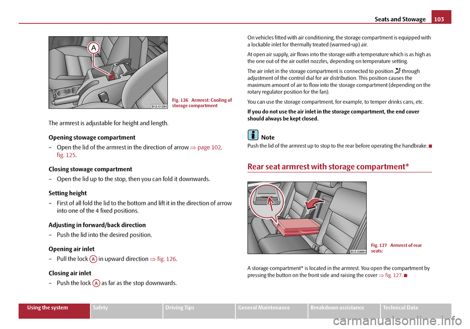
A storage compartment* is located in the armrest. You open the compartment by
pressing the button on the front side and raising the cover ⇒fig. 127 .
Fig. 126 Armrest: Cooling of
storage compartment
AA
AA
Fig. 127 Armrest of rear
seats:
20A5Facelift.book Page 103 Saturday, September 6, 2008 2:13 PM
Page 109 of 304
Heating and air conditioning system
108
Heating and air conditioning system
Air outlet vents
The information provided is valid for all vehicles.
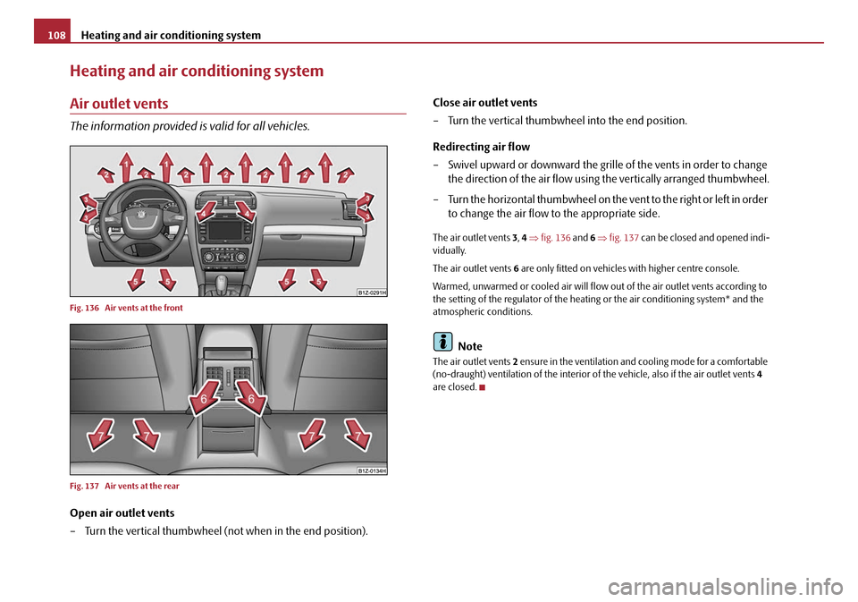
Fig. 136 Air vents at the front
Fig. 137 Air vents at the rear
Open air outlet vents
– Turn the vertical thumbwheel (not when in the end position). Close air outlet vents
– Turn the vertical thumbwheel into the end position.
Redirecting air flow
– Swivel upward or downward the grille of the vents in order to change
the direction of the air flow using the vertically arranged thumbwheel.
– Turn the horizontal thumbwheel on the vent to the right or left in order to change the air flow to the appropriate side.
The air outlet vents 3, 4 ⇒ fig. 136 and 6 ⇒ fig. 137 can be closed and opened indi-
vidually.
The air outlet vents 6 are only fitted on vehicles with higher centre console.
Warmed, unwarmed or cooled air will flow ou t of the air outlet vents according to
the setting of the regulator of the heatin g or the air conditioning system* and the
atmospheric conditions.
Note
The air outlet vents 2 ensure in the ventilation and cooling mode for a comfortable
(no-draught) ventilation of the interior of the vehicle, also if the air outlet vents 4
are closed.
20A5Facelift.book Page 108 Saturday, September 6, 2008 2:13 PM
Page 111 of 304

Heating and air conditioning system
110
•The used air streams out through the air removal openings in the luggage
compartment.
Set heating
Recommended settings of heating controls for:
Set-upSetting of the control dialButton Air outlet vents 3Air outlet vents 4
Defrosting the windscreen and
side windowsup to the stop
towards the right3do not switch onopen and align with the side windowclose
Free windscreen and side win-
dows from mistdesired tempera-ture2 or 3 or do not switch onopen and align with the side windowclose
the fastest heatingup to the stop
towards the right3briefly switched onopenopen
comfortable heatingdesired tempera- ture2 or 3do not switch onopenclose
Fresh air mode - ventilation up to the stop
towards the leftdesired positiondo not switch onopenopen
A1AAABAC
20A5Facelift.book Page 110 Saturday, September 6, 2008 2:13 PM
Page 114 of 304
Heating and air conditioning system113
Using the systemSafetyDriving TipsGeneral MaintenanceBreakdown assistanceTechnical Data
Control for air distribution
– You can adjust the direction of the air flow using the air distribution
control ⇒page 108.
switching cooling on and off
– Press the button ⇒page 112, fig. 139 . The warning light lights
up in the button.
– When you again press the switch , the cooling system is switched off. The warning light in the button goes out.
Rear window heater
– Press button . Further information ⇒page 67, “Rear window
heater”.
Auxiliary heating (auxiliary heating)
– Press the button in order to directly switch on/off the auxiliary heating (auxiliary heating and ventilation. Further information
⇒page 119, “Auxiliary heating (auxil iary heating and ventilation)*”.The set temperature will be automatically maintained other than when the
control dial is on the extreme right or extreme left position:
•Extreme right position - full heating;
•Extreme left position - full cooling;
•The blower should aways be on to prevent the windows from misting up.
Note
•The whole heat output will be needed to unfrost the windscreen and side
windows. No warm air will be fed to the footwell. This can lead to restriction of the
heating comfort.
•The used air streams out through the air removal openings in the luggage
compartment.
•If the cooling system has not been switched on for a lengthy period, odours may
be produced at the evaporator because of deposits. Switch the cooling system on
at least once a month for approximately 5 mi nutes at the highest blower stage - also
during the cold season of the year - in order to remove such odours. Also open a
window for a short time.
•Please refer to the information regarding recirculated air mode ⇒page 114.
Set Climatic
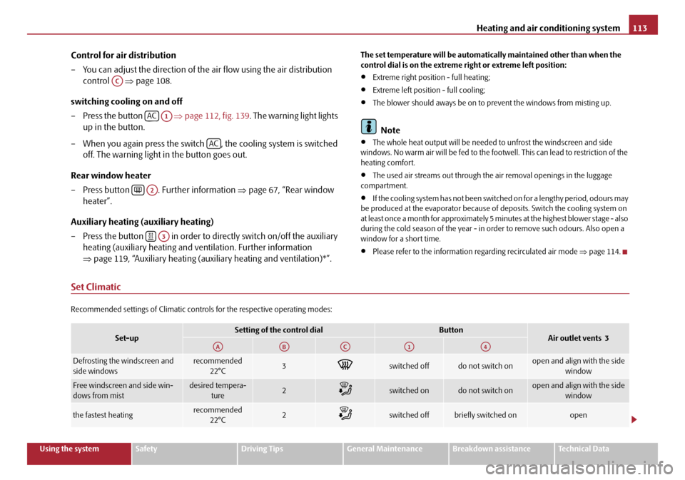
Recommended settings of Climatic controls for the respective operating modes:
AC
ACA1
AC
A2
A3
Set-upSetting of the control dialButtonAir outlet vents 3
Defrosting the windscreen and
side windowsrecommended
22°C3switched offdo not switch onopen and align with the side window
Free windscreen and side win-
dows from mistdesired tempera-ture2switched ondo not switch onopen and align with the side window
the fastest heatingrecommended
22°C2switched offbriefly switched onopen
AAABACA1A4
20A5Facelift.book Page 113 Saturday, September 6, 2008 2:13 PM
Page 115 of 304
Heating and air conditioning system
114
Recirculated air mode
In recirculated air mode air is sucked out of the interior of the vehicle
and then fed back into the interior.
Recirculated air mode prevents polluted air outside the vehicle from
getting into the vehicle, for example when driving through a tunnel or
when standing in a traffic jam.
Switching recirculated air mode on
– Press the button ⇒page 112, fig. 139 the warning light lights
up in the button.
Switching recirculated air mode off
– Press again the button - the warning light in the button goes out.
The recirculated air mode is switched off au tomatically if the air distribution control
is in position ⇒ page 112, fig. 139 . You can also switch recirculated air mode
on again from this setting by repeatedly pressing button .
WARNING
You should not leave recirculated air mode on over a longer period of time,
as “stale” air may result in fatigue in the driver and occupants, divert your
attention and also cause the windows to mist up. The risk of having an acci-
dent increases. Switch recirculated air mode off as soon as the windows
begin misting up.
Using the air conditioning system economically
The compressor on the air conditioning system uses power from the engine when
in cooling mode which will effect the fuel consumption.
It recommended to open the windows or the doors of a vehicle for which the inte-
rior has been strongly heated through the effect of direct sunlight in order to allow
the heated air to escape.
The cooling system should not be switched on while travelling when the window is
open.
The desired interior temperature can also be achieved without switching in the
cooling system just by switching to fresh air mode.
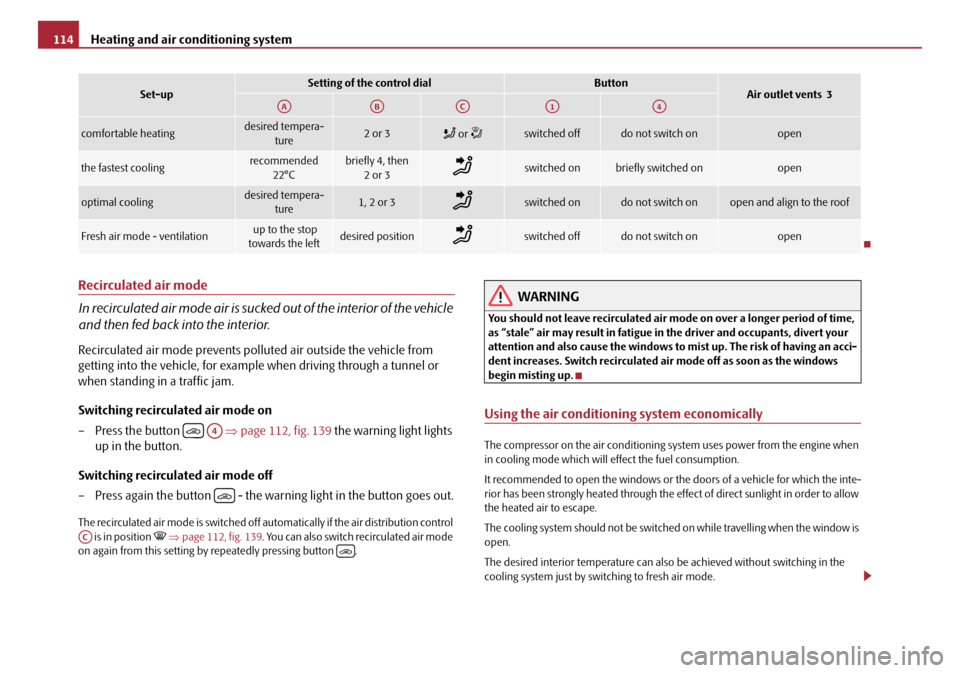
comfortable heatingdesired tempera-
ture2 or 3 or switched offdo not switch onopen
the fastest coolingrecommended
22°Cbriefly 4, then 2or 3switched onbriefly switched onopen
optimal coolingdesired tempera- ture1, 2 or 3switched ondo not switch onopen and align to the roof
Fresh air mode - ventilation up to the stop
towards the leftdesired positionswitched offdo not switch onopen
Set-upSetting of the control dialButtonAir outlet vents 3AAABACA1A4
A4
AC
20A5Facelift.book Page 114 Saturday, September 6, 2008 2:13 PM
Page 116 of 304
Heating and air conditioning system115
Using the systemSafetyDriving TipsGeneral MaintenanceBreakdown assistanceTechnical Data
For the sake of the environment
When you economize on fuel, you also reduce pollutant emissions.
Operational problems
If the cooling system does not operate at outside temperatures higher than +5 °C,
there is a problem in the system. The reasons for this may be:
•The fuse on the air conditioning system has blown. Check the fuse, replace it if
necessary ⇒page 257.
•The cooling system has switched off automatically for a short time because the
coolant temperature of the engine is too hot ⇒page 18.
If you are not able to rectify the operat ional problem yourself, or if the cooling
capacity decreases, switch the cooling sy stem off. Contact a specialist garage.
Climatronic* (automatic air conditioning)
Description
The Climatronic system is a combination of an automatic heating,
fresh air and cooling system which provides optimal comfort for the
occupants of the car.
The Climatronic maintains fully automatically a convenience temperature. This is
achieved by automatically varying the temperature of the outflowing air, the blower
stages and the air distribution. The system also takes into account sunlight which
eliminates the need to alte r the settings manually. The automatic mode
¨ ⇒ page 117 ensures maximum wellbeing of th e occupants at all times of the year.
Description of Climatronic system
The cooling operates only if the following conditions are met:
•engine running,
•outside temperature above approx. +2°C,
• switched on.
If the cooling system is switched on, th e temperature and air humidity drops in the
vehicle. The wellbeing of the occupants of the car is enhanced as a result of this
particularly at high outside temperatur es and a high air humidity. The system
prevents the windows misting up during the cold season of the year.
The heating effect is dependent upon th e coolant temperature, thus full heat
output only occurs when the engine has reached its operating temperature.
It is possible to briefly activate recirc ulated air mode in order to enhance the
cooling effect ⇒page 118.
The air inlet in front of the windscreen must be free of ice, snow or leaves in order
to ensure that the heating and cooling systems operate properly.
The AC compressor is switched off at a hi gh coolant temperature in order to provide
cooling at a high load of the engine.
After switching on the cooling Condensation from the evaporator of the air condi-
tioning may drip down and form a puddle below the vehicle. This is quite normal
and not an indication of a leak!
Recommended setting for all periods of the year:
•Set the desired temperature, we recommend 22 °C.
•Press the button ⇒page 116, fig. 140 .
•Move the air outlet vents 3 and 4 so that the air flow is directed slightly upwards.
Aeration of the vehicle when ignition is switched off*
On models fitted with power sliding/tilting roof with sollar cells, the fresh air blower
is automatically switched over to “solar mode” if the sun ray's are sufficient after
switching off the ignition. The solar cells on the sliding/tilting roof deliver power for
the fresh air blower. This supplies the interior of the car with fresh air.
For an optimum ventilation, the air outlet vents 3 and 4 must be opened
⇒ page 108, fig. 136.
The ventilation functions only when the sliding/tilting roof is closed.
AC
AUTO
20A5Facelift.book Page 115 Saturday, September 6, 2008 2:13 PM
Page 118 of 304
Heating and air conditioning system117
Using the systemSafetyDriving TipsGeneral MaintenanceBreakdown assistanceTechnical Data
Button for direct switching on/off of au
xiliary heating (auxiliary heating)*
⇒ page 119
Switching on/off of the temperature setting in dual mode
Switching cooling on and off
Setting of the temperature for the right side, operation of the seat heating of
the right front seat*
Note
Below the top row of buttons is located the interior temperature sensor. Do not
glue or cover over the sensor, otherwise it could have an unfavourable effect on the
Climatronic.
Automatic mode
The automatic mode is used in order to maintain a constant temper-
ature and to demist the windows in the interior of the car.
Switching automatic mode on
– Set a temperature between +18 °C and +26 °C.
– Move the air outlet vents 3 and 4 ⇒ page 108, fig. 136 so that the air
flow is directed slightly upwards.
– Press the button . In the right or left top corner a warning light lights up, depending on which unit was last selected.
If the warning light in the top right corner of the button lights up, the
Climatronic operates in “HIGH” mode. The “HIGH” mode is the standard setting of
the Climatronic.
When pressing again the button , the Climatronic changes into the “LOW”
mode and the warning light in the top left corner lights up. The Climatronic uses
only in this mode the lower blower speed. However taking into account the noise
level, this is more comfortable, yet be aw are that the effectiveness of the air condi-
tioning system is reduced particularly if the vehicle is fully occupied.
By pressing again the button , yo u change into the “HIGH” mode. The automatic mode is switched off by pr
essing the button for the air distribution
or increasing or decreasing the blower speed. The temperature is nevertheless
regulated.
switching cooling on and off
switching cooling on and off
– Press the button ⇒ page 116, fig. 140. The warning light lights up
in the button.
– When you again press the switch , the cooling system is switched off. The warning light in the button goes out. Only the function of the
ventilation remains active when no lower temperature than the
outside temperature can be reached.
Setting temperature
You can separate the interior temperature for the left and right side sepa-
rately.
– You can set the temperature for both sides after switching on the igni- tion with the control dial .
– If you wish to set the temperature for the right side, turn the control dial . The warning light in the bu tton lights up, this indicates
that differing temperatures for the left and right side can be set.
If the warning light in the button lights up, the temperature for both sides
cannot be set with the control dial . You can reinitiate this function by pressing
the button . The warning light in the button which indicates the possibility to
set differing temperatures for the left and right side, goes out.
You can set the interior temperature be tween +18°C and +26°C. The interior
temperature is regulated automatically within this range. If you chose a tempera-
ture lower than +18°C, a blue symbol lights up at the start of the numerical scale. If
you chose a temperature higher than +26°C, a red symbol lights up at the end of
A11
A12DUAL
A13AC
A14
AUTO
AUTO
AUTO
AUTO
AC
AC
A7
A14DUAL
DUALA7DUAL
20A5Facelift.book Page 117 Saturday, September 6, 2008 2:13 PM