back door SKODA OCTAVIA 2008 2.G / (1Z) Owner's Manual
[x] Cancel search | Manufacturer: SKODA, Model Year: 2008, Model line: OCTAVIA, Model: SKODA OCTAVIA 2008 2.G / (1Z)Pages: 304, PDF Size: 17.69 MB
Page 4 of 304
Contents3
Using the systemSafetyDriving TipsGeneral MaintenanceBreakdown assistanceTechnical Data
Contents
Layout of this Owner's Manual
(explanations)
. . . . . . . . . . . . . . . . . . . . . . . . . .
Using the system. . . . . . . . . . . . . . . . . . . . . .
Cockpit. . . . . . . . . . . . . . . . . . . . . . . . . . . . . . . . . . . . . . . .
Overview . . . . . . . . . . . . . . . . . . . . . . . . . . . . . . . . . . . .
The brief instruction . . . . . . . . . . . . . . . . . . . . . . . . . .
Basic functions and important information . . . . .
Instruments and Indicator/Warning Lights. . .
General view of the instrument cluster . . . . . . . . .
Engine revolutions counter . . . . . . . . . . . . . . . . . . . .
Speedometer . . . . . . . . . . . . . . . . . . . . . . . . . . . . . . . .
Coolant temperature gauge . . . . . . . . . . . . . . . . . . .
Fuel gauge . . . . . . . . . . . . . . . . . . . . . . . . . . . . . . . . . . .
Counter for distance driven . . . . . . . . . . . . . . . . . . .
Service Interval Display . . . . . . . . . . . . . . . . . . . . . . .
Digital clock . . . . . . . . . . . . . . . . . . . . . . . . . . . . . . . . . .
Multi-functional indicato r (onboard computer)*
Information display* . . . . . . . . . . . . . . . . . . . . . . . . . .
Audio . . . . . . . . . . . . . . . . . . . . . . . . . . . . . . . . . . . . . . . .
Navigation system* . . . . . . . . . . . . . . . . . . . . . . . . . . .
Auto Check Control* . . . . . . . . . . . . . . . . . . . . . . . . . .
Warning lights . . . . . . . . . . . . . . . . . . . . . . . . . . . . . . . .
Unlocking and locking . . . . . . . . . . . . . . . . . . . . . . . .
Key . . . . . . . . . . . . . . . . . . . . . . . . . . . . . . . . . . . . . . . . . .
Key with light* . . . . . . . . . . . . . . . . . . . . . . . . . . . . . . . .
Changing the battery of the radio remote control
Electronic immobiliser . . . . . . . . . . . . . . . . . . . . . . . .
Child safety lock . . . . . . . . . . . . . . . . . . . . . . . . . . . . . .
Central locking system . . . . . . . . . . . . . . . . . . . . . . . .
Remote control* . . . . . . . . . . . . . . . . . . . . . . . . . . . . . . Synchonisation of the remote control . . . . . . . . . .
Anti-theft alarm system* . . . . . . . . . . . . . . . . . . . . . .
Power windows* . . . . . . . . . . . . . . . . . . . . . . . . . . . . .
Electric sliding/tilting roof* . . . . . . . . . . . . . . . . . . . .
Lights and Visibility . . . . . . . . . . . . . . . . . . . . . . . . . . .
Lights . . . . . . . . . . . . . . . . . . . . . . . . . . . . . . . . . . . . . . . .
Interior lighting . . . . . . . . . . . . . . . . . . . . . . . . . . . . . . .
Visibility . . . . . . . . . . . . . . . . . . . . . . . . . . . . . . . . . . . . .
Windshield wiper and wash system . . . . . . . . . . . .
Rear-view mirror . . . . . . . . . . . . . . . . . . . . . . . . . . . . .
Seats and Stowage. . . . . . . . . . . . . . . . . . . . . . . . . . . .
Front seats . . . . . . . . . . . . . . . . . . . . . . . . . . . . . . . . . . .
Adjusting front seats electrically* . . . . . . . . . . . . . .
Head restraints . . . . . . . . . . . . . . . . . . . . . . . . . . . . . . .
Middle rear head restraint* . . . . . . . . . . . . . . . . . . . .
Rear seats . . . . . . . . . . . . . . . . . . . . . . . . . . . . . . . . . . . .
Pedals . . . . . . . . . . . . . . . . . . . . . . . . . . . . . . . . . . . . . . .
luggage compartment . . . . . . . . . . . . . . . . . . . . . . . .
Net partition (Estate)* . . . . . . . . . . . . . . . . . . . . . . . .
The roof rack* . . . . . . . . . . . . . . . . . . . . . . . . . . . . . . . .
Cup holder . . . . . . . . . . . . . . . . . . . . . . . . . . . . . . . . . . .
Note holder . . . . . . . . . . . . . . . . . . . . . . . . . . . . . . . . . .
Ashtray* . . . . . . . . . . . . . . . . . . . . . . . . . . . . . . . . . . . . .
Cigarette lighter*, power sockets . . . . . . . . . . . . . . .
Storage compartments . . . . . . . . . . . . . . . . . . . . . . . .
Overview . . . . . . . . . . . . . . . . . . . . . . . . . . . . . . . . . . . .
Storage compartment on the front passenger side
Cooling of storage compartment on front
passenger side* . . . . . . . . . . . . . . . . . . . . . . . . . . . . . .
Storage compartment on the driver's side . . . . . .
Storage compartment on the dash panel* . . . . . .
Stowage compartment in front centre console* .
Storage net on the front centre console* . . . . . . . Stowage compartment for spectacles* . . . . . . . . .
Storage compartment in the front doors . . . . . . .
Stowage compartment below front passenger
seat* . . . . . . . . . . . . . . . . . . . . . . . . . . . . . . . . . . . . . . . .
Front seat armrest with storage compartment* .
Rear seat armrest with storage compartment* . .
Stowage compartment in rear centre console* .
Seat backrest with opening for skis* . . . . . . . . . . . .
Through-loading bag* . . . . . . . . . . . . . . . . . . . . . . . .
Side compartment* . . . . . . . . . . . . . . . . . . . . . . . . . .
Stowage compartment behind the rear seats
(estate car) . . . . . . . . . . . . . . . . . . . . . . . . . . . . . . . . . . .
Clothes hooks* . . . . . . . . . . . . . . . . . . . . . . . . . . . . . .
Heating and air conditioning system. . . . . . . . .
Air outlet vents . . . . . . . . . . . . . . . . . . . . . . . . . . . . . . .
Heating . . . . . . . . . . . . . . . . . . . . . . . . . . . . . . . . . . . . . .
Climatic* (semi-automatic air conditioning
system) . . . . . . . . . . . . . . . . . . . . . . . . . . . . . . . . . . . . . .
Climatronic* (automatic air conditioning) . . . . . .
Auxiliary heating (auxiliary heating and
ventilation)* . . . . . . . . . . . . . . . . . . . . . . . . . . . . . . . . .
Starting-off and Driving . . . . . . . . . . . . . . . . . . . . . .
Setting steering wheel position . . . . . . . . . . . . . . . .
Ignition lock . . . . . . . . . . . . . . . . . . . . . . . . . . . . . . . . .
Starting the engine . . . . . . . . . . . . . . . . . . . . . . . . . . .
Switching off the engine . . . . . . . . . . . . . . . . . . . . . .
Shifting (manual gearbox) . . . . . . . . . . . . . . . . . . . . .
Handbrake . . . . . . . . . . . . . . . . . . . . . . . . . . . . . . . . . . .
Rear parking aid* . . . . . . . . . . . . . . . . . . . . . . . . . . . . .
Front and rear parking aid* . . . . . . . . . . . . . . . . . . . .
Cruise control system (CCS)* . . . . . . . . . . . . . . . . . .
Automatic gearbox . . . . . . . . . . . . . . . . . . . . . . . . . . .
Automatic gearbox* . . . . . . . . . . . . . . . . . . . . . . . . . .
6
7
9
9
11
11
17
17
18
18
18
18
19
20
21
21
26
28
28
28
32
42
42
42
43
44
44
45
49 51
51
53
56
59
59
66
67
69
73
76
76
77
80
81
81
85
85
91
93
94
95
95
97
98
98
99
99
100
100
101
101 101
102
102
102
103
104
104
105
106
106
107
108
108
109
111
115
119
124
124
125
126
127
127
128
129
130
131
134
134
20A5Facelift.book Page 3 Saturday, September 6, 2008 2:13 PM
Page 31 of 304
Instruments and Indicator/Warning Lights
30
Set-up
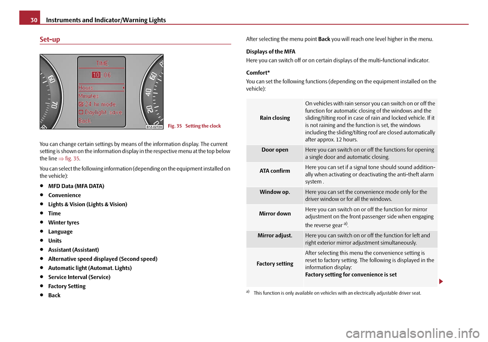
You can change certain settings by means of the information display. The current
setting is shown on the information displa y in the respective menu at the top below
the line ⇒fig. 35 .
You can select the following information (d epending on the equipment installed on
the vehicle):
•MFD Data (MFA DATA)
•Convenience
•Lights & Vision (Lights & Vision)
•Time
•Winter tyres
•Language
•Units
•Assistant (Assistant)
•Alternative speed displayed (Second speed)
•Automatic light (Automat. Lights)
•Service Interval (Service)
•Factory Setting
•Back After selecting the menu point
Back you will reach one level higher in the menu.
Displays of the MFA
Here you can switch off or on certain di splays of the multi-functional indicator.
Comfort*
You can set the following functions (depen ding on the equipment installed on the
vehicle):
Fig. 35 Setting the clock
Rain closing
On vehicles with rain sensor you can switch on or off the
function for automatic closing of the windows and the
sliding/tilting roof in case of rain and locked vehicle. If it
is not raining and the function is set, the windows
including the sliding/tilting roof are closed automatically
after approx. 12 hours.
Door openHere you can switch on or of f the functions for opening
a single door and automatic closing.
ATA confirmHere you can set if a signal tone should sound addition-
ally when activating or deactivating the anti-theft alarm
system .
Window op.Here you can set the convenience mode only for the
driver window or for all the windows.
Mirror downHere you can switch on or off the function for mirror
adjustment on the front passe nger side when engaging
the reverse gear
a).
a)This function is only available on vehicles with an electrically adjustable driver seat.
Mirror adjust.Here you can switch on or off the function for left and
right exterior mirror adjustment simultaneously.
Fa c t o r y s e t t i n g
After selecting this menu the convenience setting is
reset to factory setting. The following is displayed in the
information display:
Factory setting for convenience is set
20A5Facelift.book Page 30 Saturday, September 6, 2008 2:13 PM
Page 56 of 304
Unlocking and locking55
Using the systemSafetyDriving TipsGeneral MaintenanceBreakdown assistanceTechnical Data
The force limiter is only switched off, if you attempt to close the window within the
next 10 seconds -
the window closes now with full strength!
If you wait longer than 10 seconds, the force limiter is switched on again.
WARNING
You should take particular care when closing the windows! You may other-
wi se s uffe r s e ve re i njur ie s a s a re sul t of getting an arm, for example, jammed
in the window!
Window convenience operation
You can open and close the electrically powered windows as follows
when unlocking and locking the vehicle (just closing of the sliding roof).
Opening a window
– Turn the key in the lock of the driver door into the opening position or
press the opening button of the radio remote control until all the
windows are open.
Closing a window
– Turn the key in the lock of the driver door into the closing position or press the closing button of the radio remote control until all the
windows are closed.
You can interrupt the opening or closing operation of the windows immediately by
releasing the key or the closing button.
WARNING
The system is fitted with a force limiter ⇒page 54. The clos ing process will
be stop if an obstruction is detected and the window will open again. You
should then take particular care when closing the windows! You may other- wis e suf fe r se v e re inj uri es a s a re s ult of g e tt ing a n ar m , for e xa m ple , ja m m e d
in the window!
Note
•On vehicles fitted with anti-theft
alarm system the convenience window
opening is possible by means of the key in the lock only 45 seconds after deacti-
vating the warning system or after ac tivating the anti-theft alarm system.
Operational faults
Electrically operated power windows do not operate
If the battery of the car has been disconnected and then reconnected, the electri-
cally operated power windows do not operate. The system must be activated.
Proceed as follows in order to re-establish the function:
•Switch on the ignition.
•Press the relevant switch top and hold it pressed as long as necessary until the
window is closed.
•Release the switch.
•Press once again the relevant switch top and hold it pressed for approx. 3
seconds.
Operation in winter
Ice accumulating on the surface of the wi ndows during the winter may result in a
greater resistance when closing the windows and the window may stop and move
back several centimetres
Proceed as follows to close the window fully:
•Turn the key in the lock of the driver d oor into the closing position and hold it
there until all of the windows are closed.
•repeat this operation until the window stops.
WARNING (continued)
20A5Facelift.book Page 55 Saturday, September 6, 2008 2:13 PM
Page 74 of 304
Lights and Visibility73
Using the systemSafetyDriving TipsGeneral MaintenanceBreakdown assistanceTechnical Data
Rear-view mirror
Manual dimming interior rear-view mirror
Basic setting
– Pull the lever on the bottom edge of the mirror forward.
Dimming mirror
– Pull the lever on the bottom edge of the mirror back.
Automatic dimming interior mirror*
Switching on the automatic dimming
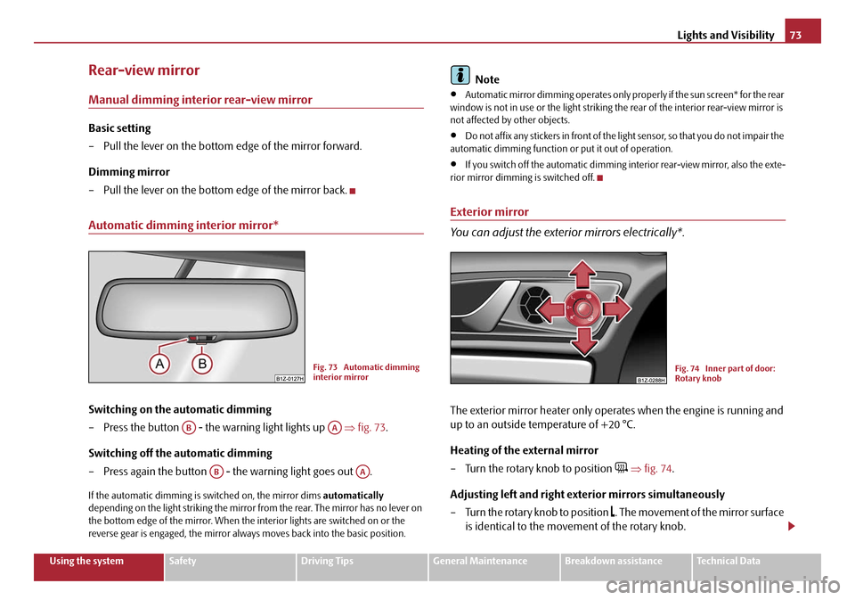
– Press the button - the warning light lights up ⇒fig. 73 .
Switching off the automatic dimming
– Press again the button - the warning light goes out .
If the automatic dimming is switched on, the mirror dims automatically
depending on the light striking the mirror from the rear. The mirror has no lever on
the bottom edge of the mirror. When the interior lights are switched on or the
reverse gear is engaged, the mirror alwa ys moves back into the basic position.
Note
•Automatic mirror dimming operates only pr operly if the sun screen* for the rear
window is not in use or the light striking th e rear of the interior rear-view mirror is
not affected by other objects.
•Do not affix any stickers in front of the li ght sensor, so that you do not impair the
automatic dimming function or put it out of operation.
•If you switch off the automatic dimming interior rear-view mirror, also the exte-
rior mirror dimming is switched off.
Exterior mirror
You can adjust the exterior mirrors electrically*.
The exterior mirror heater only oper ates when the engine is running and
up to an outside temperature of +20 °C.
Heating of the external mirror
– Turn the rotary knob to position
⇒ fig. 74 .
Adjusting left and right exterior mirrors simultaneously
– Turn the rotary knob to position
. The movement of the mirror surface
is identical to the movement of the rotary knob.
Fig. 73 Automatic dimming
interior mirror
ABAA
ABAA
Fig. 74 Inner part of door:
Rotary knob
20A5Facelift.book Page 73 Saturday, September 6, 2008 2:13 PM
Page 81 of 304
Seats and Stowage
80
Retrieving settings with remote control
– If the driver door is clos ed and the ignition is switched off, briefly press
the unlock button of the remote control ⇒page 50 and then open the
driver door.
– The seat and exterior mirrors now move automatically into the stored positions.
Retrieving setting of exterior mirror for reversing*
– Turn the rotary knob for the exterior mirror setting into the position
⇒ page 73 before engaging the reverse gear.
The mirror returns back into its initial po sition, after the rotary knob is moved out
of the position and put into another position or if the speed is more than 15 km/h.
Emergency Off
You can interrupt the setting operation at an y time, if you operate any button of the
driver seat.
Head restraints
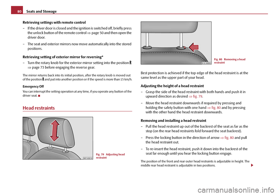
Best protection is achieved if the top edge of the head restraint is at the
same level as the upper part of your head.
Adjusting the height of a head restraint
– Grasp the side of the head restraint with both hands and push it in upward direction as desired ⇒fig. 79 .
– Move the head restraint downwards if required by pressing and holding the safety button with one hand ⇒fig. 80 and by pressing
with the other hand the head restraint downwards.
Removing and installing a head restraint
– Pull the head restraint up out of the backrest of the seat as far as the stop (on the rear head restraints fold forward the seat backrest).
– Press the locking button in the direction of arrow ⇒fig. 80 and pull
the head restraint out.
– To re-insert the head restraint, push it down into the backrest of the seat far enough until you hear the locking button engage.
The position of the front and rear outer head restraints is adjustable in height. The
middle rear head restraint is adjustable in two positions.
Fig. 79 Adjusting head
restraint
Fig. 80 Removing a head
restraint
20A5Facelift.book Page 80 Saturday, September 6, 2008 2:13 PM
Page 93 of 304

Seats and Stowage
92
Use behind the front seats
Unrolling
– Fold the rear seats forwards ⇒page 81
– Pull the net partiton net at the plate out of the housing ⇒fig. 104 .
– Insert the cross rod into the mount first on the one side and push the cross rod forward.
– In the same way, fix the cross rod to the other side of the vehicle, mount .
Rolling up
– Pull the cross rod back slightly, first on the one side then on the other side and take the cross rod out of the mount ⇒fig. 104.
– Hold the cross rod in such a way that the net partition can roll up
slowily and without damage into housing .
– Fold the rear seats back into its original position.
WARNING
•The belt locks and the belts must be in their original position after folding
back the rear seats and seat backrests - they must be ready to use.
•The seat backrests must be securely interlocked in position so that no
objects in the luggage compartment can slide into the passenger compart-
ment if there is sudden braking - risk of injury!
•Pay attention that the rear seat backrest is correctly interlocked. It is only
then that the three-point seat belt for the middle seat can reliably fulfil its
function.
•First check for yourself that the cross road is inserted into the mounts
in the front position!
Removing and installing net partition housing
Removing
– Fold the rear seats forwards ⇒page 81
– Open the right rear door.
– Push the net partition housing ⇒fig. 105 in the direction of arrow
and take it out of the mounts of the rear seat backrests in the direc-
tion of the arrow .
Fig. 104 Unrolling net parti-
tion
AAAB
AC
AC
AC
AB
AC
Fig. 105 Rear seats: Net
partition housing
AA
A1
A2
20A5Facelift.book Page 92 Saturday, September 6, 2008 2:13 PM
Page 99 of 304
Seats and Stowage
98
WARNING
•Take care when using the cigarette lighter! Not paying proper attention
or incorrect use the cigarette lighter in an uncontrolled manner may result in
burns.
•The cigarette lighter and the power so cket also operates when the igni-
tion is switched off or the ignition key withdrawn. You should therefore
never leave children unattended in the vehicle.
Caution
Always use matching plugs to av oid damaging the power socket.
Note
•Connecting electrical components when the engine is not running will
drain the battery of the vehicle - risk of battery draining!
•Further information ⇒page 243, “Accessories, changes and replacement of
parts”.
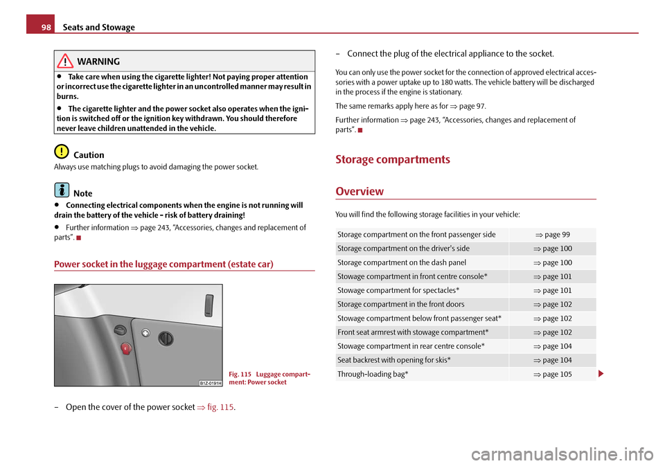
Power socket in the luggage compartment (estate car)
– Open the cover of the power socket ⇒fig. 115 . – Connect the plug of the electr
ical appliance to the socket.
You can only use the power socket for the connection of approved electrical acces-
sories with a power uptake up to 180 watts. The vehicle battery will be discharged
in the process if the engine is stationary.
The same remarks apply here as for ⇒page 97.
Further information ⇒page 243, “Accessories, changes and replacement of
parts”.
Storage compartments
Overview
You will find the following stor age facilities in your vehicle:
Fig. 115 Luggage compart-
ment: Power socket
Storage compartment on the front passenger side⇒page 99
Storage compartment on the driver's side⇒page 100
Storage compartment on the dash panel⇒page 100
Stowage compartment in front centre console*⇒page 101
Stowage compartment for spectacles*⇒page 101
Storage compartment in the front doors⇒page 102
Stowage compartment below front passenger seat*⇒page 102
Front seat armrest with stowage compartment*⇒page 102
Stowage compartment in rear centre console*⇒page 104
Seat backrest with opening for skis*⇒page 104
Through-loading bag*⇒page 105
20A5Facelift.book Page 98 Saturday, September 6, 2008 2:13 PM
Page 115 of 304
Heating and air conditioning system
114
Recirculated air mode
In recirculated air mode air is sucked out of the interior of the vehicle
and then fed back into the interior.
Recirculated air mode prevents polluted air outside the vehicle from
getting into the vehicle, for example when driving through a tunnel or
when standing in a traffic jam.
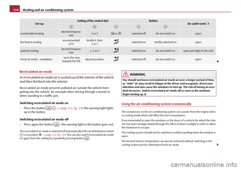
Switching recirculated air mode on
– Press the button ⇒page 112, fig. 139 the warning light lights
up in the button.
Switching recirculated air mode off
– Press again the button - the warning light in the button goes out.
The recirculated air mode is switched off au tomatically if the air distribution control
is in position ⇒ page 112, fig. 139 . You can also switch recirculated air mode
on again from this setting by repeatedly pressing button .
WARNING
You should not leave recirculated air mode on over a longer period of time,
as “stale” air may result in fatigue in the driver and occupants, divert your
attention and also cause the windows to mist up. The risk of having an acci-
dent increases. Switch recirculated air mode off as soon as the windows
begin misting up.
Using the air conditioning system economically
The compressor on the air conditioning system uses power from the engine when
in cooling mode which will effect the fuel consumption.
It recommended to open the windows or the doors of a vehicle for which the inte-
rior has been strongly heated through the effect of direct sunlight in order to allow
the heated air to escape.
The cooling system should not be switched on while travelling when the window is
open.
The desired interior temperature can also be achieved without switching in the
cooling system just by switching to fresh air mode.
comfortable heatingdesired tempera-
ture2 or 3 or switched offdo not switch onopen
the fastest coolingrecommended
22°Cbriefly 4, then 2or 3switched onbriefly switched onopen
optimal coolingdesired tempera- ture1, 2 or 3switched ondo not switch onopen and align to the roof
Fresh air mode - ventilation up to the stop
towards the leftdesired positionswitched offdo not switch onopen
Set-upSetting of the control dialButtonAir outlet vents 3AAABACA1A4
A4
AC
20A5Facelift.book Page 114 Saturday, September 6, 2008 2:13 PM
Page 144 of 304
Communication143
Using the systemSafetyDriving TipsGeneral MaintenanceBreakdown assistanceTechnical Data
Universal telephone preinstallation GSM II*
Introduction
This enables you to make full use of the advantages of a normal carphone (“hands-
free system - Hands Free” using a micropho ne integrated in the vehicle, optimal
transmission of signals using an external aerial
15) etc.). The equipment includes
also the voice control. The telephone is connected by means of the Bluetooth®
technology ⇒page 144, “Bluetooth®”. On vehicles fitted with a telephone
mount*, it is also possible to establish the connection via the interface of the
adapter
16) ⇒ page 145, “Operating telephone calls with the aid of the adapter*.”.
A phone phonebook is part of the mobile ph one preinstallation with voice control.
In the phone phonebook there are 1500 free memory locations available. This
phone phonebook is independent of the appliance used for the mobile phone.
Furthermore the volume can be changed individually during the call at any time
with the button for setting the radio* or on vehicles fitted with multifunction
steering wheel* with function buttons on the steering wheel.
If the system answers with the voice response “ Telephone is not ready”, please
check the operating state of the telephone as follows:
•Is the telephone switched on?
•Is the PIN code entered?
Dialogue
The period, in which the telephone system is ready to receive voice commands and
carry out the voice commands, is called DIALOGUE. The system gives audible feed-
back and guides you if necessary through the relevant functions. You can start or
end the dialogue at any time by pres sing the PTT button on the adapter*
⇒ page 145 or on the multifunction steering wheel* ⇒page 146.
The dialogue is always automatically ended after carrying out an operation, e.g.
after erasing the name from the phonebook. When receiving an incoming call, the dialogue is immediately interrupted and you
can accept the call by pressing the button
on the multifunction steering wheel*
⇒ page 146 or by pressing the button for receiving a call directly on your tele-
phone.
If a voice command is not detected, the system answers with “ Sorry?” and a new
entry can be performed. After the 2nd error the system repeats the aid. After the 3rd
error the answer “ Cancel” is given and the dialogue is ended.
Optimum understanding of the voice commands depends on the following
factors:
•Speak with a normal tone of voice without intonation and excessive voice
pauses.
•Avoid insufficient articulation.
•Close the doors, windows and sliding roof, in order to reduce or stop disturbing
exterior noise.
•It is recommended to speak louder at higher speeds, so that the tone of your
voice is louder than the increased surrounding noise.
•During the dialogue avoid additional noise in the vehicle, e.g. simultaneously
talking occupants.
•Do not speak, if the system makes an announcement.
•The microphone for voice control is direct ed to the driver and front passenger.
Therefore the driver and the front passenger can operate the equipment.
WARNING
Pay attention primarily to the traffic situation! As the driver you are fully
responsible for road safety. Use the tele phone system only to such an extent,
so that you are in full contro l of your vehicle at any time.
Caution
Taking the mobile phone out of the adapter during the call can lead to interruption
of the connection. When taking out the mobile phone, the connection to the
factory-fitted antenna is interrupted, this reduces the quality of the transmitting
and receiving signal. This might result a dditionally in harmful radiation from the
15)Valid for telephone used with adapter* in the telephone mount.16)Not valid for adapter “Bluetooth only” ⇒page 146.
20A5Facelift.book Page 143 Saturday, September 6, 2008 2:13 PM
Page 179 of 304
Airbag system
178
Side airbags*
Description of side airbags
The side airbag together with the he ad airbag offers enhanced occu-
pant protection in the event of a side collision.
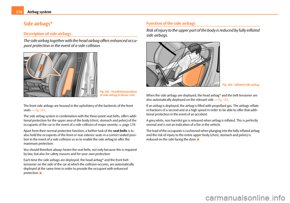
The front side airbags are housed in the upholstery of the backrests of the front
seats ⇒fig. 181 .
The side airbag system in combination with the three-point seat belts, offers addi-
tional protection for the upper area of th e body (chest, stomach and pelvis) of the
occupants of the car in the event of a side collision of major severity ⇒page 179.
Apart from their normal protective function, a further task of the seat belts is to
also hold the occupents of the front or rear exterior seats in a correct seated posi-
tion in the event of a side collision so as to enable the side airbag to offer the
maximum protection.
You should therefore always fasten the seat belts, not only because this is required
by law, but also for safety reasons and for your own protection.
Each time the side airbags are deployed, the head airbag* and the front belt
tensioner on the side of the car at which the collision occures, are automatically
deployed at the same time in order to provide the occupant with enhanced
protection.
Function of the side airbags
Risk of injury to the upper part of the body is reduced by fully inflated
side airbags.
When the side airbags are deployed, the head airbag* and the belt tensioner are
also automatically deployed on the relevant side ⇒fig. 182.
If an airbag is deployed, th e airbag is filled with propellant gas. The airbags inflate
in fractions of a second and at a high speed in order to be able to offer that addi-
tional protection in the event of an accident.
A grey white, non harmful gas is released when airbag is inflated. This is perfectly
normal and is not an indicati on of a fire in the vehicle.
The load of the occupants is cushioned when plunging into the fully inflated airbag
and the risk of injury to the entire up per body (chest, stomach and pelvis) is
reduced on the side facing the door.Fig. 181 Installation position
of side airbag in driver seat
Fig. 182 Inflated side airbag
20A5Facelift.book Page 178 Saturday, September 6, 2008 2:13 PM