bulb SKODA OCTAVIA 2008 2.G / (1Z) Owner's Manual
[x] Cancel search | Manufacturer: SKODA, Model Year: 2008, Model line: OCTAVIA, Model: SKODA OCTAVIA 2008 2.G / (1Z)Pages: 304, PDF Size: 17.69 MB
Page 5 of 304
Contents
4
Communication. . . . . . . . . . . . . . . . . . . . . . . . . . . . . . .
Multifunction steering wheel* . . . . . . . . . . . . . . . . .
Universal telephone preinstallation GSM II* . . . . .
Phone voice phonebook* . . . . . . . . . . . . . . . . . . . . .
Universal telephone preinstallation GSM III* . . . .
Phone voice phonebook* . . . . . . . . . . . . . . . . . . . . .
Mobile phones and two-way radio systems . . . . .
Input AUX-IN* . . . . . . . . . . . . . . . . . . . . . . . . . . . . . . . .
MDI input* . . . . . . . . . . . . . . . . . . . . . . . . . . . . . . . . . . .
CD changer* . . . . . . . . . . . . . . . . . . . . . . . . . . . . . . . . .
Safety. . . . . . . . . . . . . . . . . . . . . . . . . . . . . . . . . . . . . . .
Passive Safety . . . . . . . . . . . . . . . . . . . . . . . . . . . . . . . . .
Basic information . . . . . . . . . . . . . . . . . . . . . . . . . . . . .
Correct seated position . . . . . . . . . . . . . . . . . . . . . . .
Seat belts. . . . . . . . . . . . . . . . . . . . . . . . . . . . . . . . . . . . . .
Why seat belts? . . . . . . . . . . . . . . . . . . . . . . . . . . . . . . .
The physical principle of a frontal collision . . . . . .
Important safety information regarding the use of seat
belts . . . . . . . . . . . . . . . . . . . . . . . . . . . . . . . . . . . . . . . . .
How are seat belts correctly fastened? . . . . . . . . . .
Airbag system . . . . . . . . . . . . . . . . . . . . . . . . . . . . . . . . .
Description of the airbag system . . . . . . . . . . . . . . .
Front airbag . . . . . . . . . . . . . . . . . . . . . . . . . . . . . . . . . .
Side airbags* . . . . . . . . . . . . . . . . . . . . . . . . . . . . . . . . .
Head airbags* . . . . . . . . . . . . . . . . . . . . . . . . . . . . . . . .
Deactivating an airbag . . . . . . . . . . . . . . . . . . . . . . . .
Transporting children safely . . . . . . . . . . . . . . . . . .
What you should know about transporting children!
Child seat . . . . . . . . . . . . . . . . . . . . . . . . . . . . . . . . . . . .
Attaching a child seat using the “ISOFIX” system .
Attaching child seat using the “Top Tether” system
Driving Tips. . . . . . . . . . . . . . . . . . . . . . . . . . . . . .
Intelligent Technology. . . . . . . . . . . . . . . . . . . . . . . . .
Electronic stability programme (ESP)* . . . . . . . . . .
Brakes . . . . . . . . . . . . . . . . . . . . . . . . . . . . . . . . . . . . . . .
Brake booster . . . . . . . . . . . . . . . . . . . . . . . . . . . . . . . .
Antilock brake system (ABS) . . . . . . . . . . . . . . . . . . .
Brake Assist* . . . . . . . . . . . . . . . . . . . . . . . . . . . . . . . . .
Uphill-Start off-Assist* . . . . . . . . . . . . . . . . . . . . . . . .
Electromechanical power steering . . . . . . . . . . . . .
Tyre inflation pressure-control system* . . . . . . . . .
Diesel particle filter* (diesel engine) . . . . . . . . . . . .
Driving and the Environment . . . . . . . . . . . . . . . . .
The first 1 500 kilometres and then afterwards . .
Catalytic converter . . . . . . . . . . . . . . . . . . . . . . . . . . . .
Driving in an economical and environmentally
conscious manner . . . . . . . . . . . . . . . . . . . . . . . . . . . .
Environmental compatibility . . . . . . . . . . . . . . . . . . .
Motoring abroad . . . . . . . . . . . . . . . . . . . . . . . . . . . . .
Avoiding damage to your vehicle . . . . . . . . . . . . . . .
Towing a trailer. . . . . . . . . . . . . . . . . . . . . . . . . . . . . . . .
Towing a trailer . . . . . . . . . . . . . . . . . . . . . . . . . . . . . . .
General Maintenance. . . . . . . . . . . . . . .
Taking care of your vehicle and cleaning the
vehicle. . . . . . . . . . . . . . . . . . . . . . . . . . . . . . . . . . . . . . . . .
General . . . . . . . . . . . . . . . . . . . . . . . . . . . . . . . . . . . . . .
Care of the exterior of vehicle . . . . . . . . . . . . . . . . . .
Care of the interior of vehicle . . . . . . . . . . . . . . . . . .
Fuel. . . . . . . . . . . . . . . . . . . . . . . . . . . . . . . . . . . . . . . . . . . .
Petrol . . . . . . . . . . . . . . . . . . . . . . . . . . . . . . . . . . . . . . . .
Biofuel Ethanol E85* . . . . . . . . . . . . . . . . . . . . . . . . . .
Diesel . . . . . . . . . . . . . . . . . . . . . . . . . . . . . . . . . . . . . . . .
Refuelling . . . . . . . . . . . . . . . . . . . . . . . . . . . . . . . . . . . .
Inspecting and replenishing . . . . . . . . . . . . . . . . . .
Engine compartment . . . . . . . . . . . . . . . . . . . . . . . . .
Engine oil . . . . . . . . . . . . . . . . . . . . . . . . . . . . . . . . . . . . Cooling system . . . . . . . . . . . . . . . . . . . . . . . . . . . . . . .
Brake fluid . . . . . . . . . . . . . . . . . . . . . . . . . . . . . . . . . . . .
Battery . . . . . . . . . . . . . . . . . . . . . . . . . . . . . . . . . . . . . . .
Windshield washer system . . . . . . . . . . . . . . . . . . . .
Wheels and Tyres. . . . . . . . . . . . . . . . . . . . . . . . . . . . . .
Wheels . . . . . . . . . . . . . . . . . . . . . . . . . . . . . . . . . . . . . . .
Accessories, changes and replacement of partsAccessories and replacement parts . . . . . . . . . . . . .
Technical changes . . . . . . . . . . . . . . . . . . . . . . . . . . . . .
Breakdown assistance . . . . . . . . . . . . . .
Breakdown assistance. . . . . . . . . . . . . . . . . . . . . . . . .
First-aid box* and Warning triangle* (Octavia) . . .
First-aid box* and warning triangle* (Estate car) .
Fire extinguisher* . . . . . . . . . . . . . . . . . . . . . . . . . . . . .
Vehicle tool kit . . . . . . . . . . . . . . . . . . . . . . . . . . . . . . . .
Tyre repair kit* . . . . . . . . . . . . . . . . . . . . . . . . . . . . . . . .
Spare wheel* . . . . . . . . . . . . . . . . . . . . . . . . . . . . . . . . .
Changing a wheel . . . . . . . . . . . . . . . . . . . . . . . . . . . . .
Jump-starting . . . . . . . . . . . . . . . . . . . . . . . . . . . . . . . .
Tow-starting and towing vehicle . . . . . . . . . . . . . . . .
Fuses and light bulbs. . . . . . . . . . . . . . . . . . . . . . . . . .
Electric fuses . . . . . . . . . . . . . . . . . . . . . . . . . . . . . . . . .
Bulbs . . . . . . . . . . . . . . . . . . . . . . . . . . . . . . . . . . . . . . . .
Technical Data . . . . . . . . . . . . . . . . . . . . . . . . . .
Technical Data. . . . . . . . . . . . . . . . . . . . . . . . . . . . . . . . .
General information . . . . . . . . . . . . . . . . . . . . . . . . . . .
Used abbreviations . . . . . . . . . . . . . . . . . . . . . . . . . . .
Performances . . . . . . . . . . . . . . . . . . . . . . . . . . . . . . . . .
Weight . . . . . . . . . . . . . . . . . . . . . . . . . . . . . . . . . . . . . . .
Identification details . . . . . . . . . . . . . . . . . . . . . . . . . .
Fuel consumption according to the regulations
(99/100/EU) . . . . . . . . . . . . . . . . . . . . . . . . . . . . . . . . . .
Dimensions . . . . . . . . . . . . . . . . . . . . . . . . . . . . . . . . . .
Engine oil specifications . . . . . . . . . . . . . . . . . . . . . . .
141
141
143
150
152
158
160
161
161
162
163
163
163
164
168
168
169
169
170
174
174
175
178
180
181
184
184
187
190
191
193
193
193
196
197
197
197
198
198
199
200
201
201
202
202
206
206
207
208
208
211
211
211
211
216
219
219
219
221
222
224
224
227228
231
232
235
237
237
243
243
243
245
245
245
245
245
246
246
247
247
252
253
257
257
262
269
269
269
269
269
269
269
270
271
272
20A5Facelift.book Page 4 Saturday, September 6, 2008 2:13 PM
Page 33 of 304

Instruments and Indicator/Warning Lights
32
Warning lights
Overview
The warning lights indicate certain functions or faults.
Fig. 36 Instrument cluster with warning lights
Turn signal lights (to the left)⇒ page 33
Turn signal lights (to the right)⇒page 33
Fog lights⇒page 34
Main beam light⇒page 34
Low beam⇒page 34
Rear fog light⇒page 34
Speed regulating system*⇒page 34
Failure of the light bulbs⇒page 34
Diesel particle filter* (diesel engine)⇒page 34
Airbag system⇒page 35
Control system for exhaust⇒page 35
20A5Facelift.book Page 32 Saturday, September 6, 2008 2:13 PM
Page 35 of 304

Instruments and Indicator/Warning Lights
34
Further information about the turn signal system ⇒page 65.
Fog lights
The warning light comes on when the fog lights are operating ⇒page 62.
Main beam
The indicator light comes on when the main beam is selected or also when the
headlight flasher is operated.
Further information about the main beam ⇒page 65.
Low beam
The warning light comes on when low beam is selected ⇒page 59.
Rear fog light
The warning light comes on when the rear fog lights are operating ⇒page 63.
Cruise control system*
The warning light lights up, when operating the speed regulating system.
Failure of the light bulbs
The warning light comes on if a light bulb is damaged:
•up to 2 seconds after the ignition is switched on;
•when switching on the defective light bulb. The following text e.g will be displayed in the information display*:
Check front right dipped beam!
The rear side lights and the licence plate lighting require several light bulbs. The
indicator light
only lights up if all light bulbs of the licence plate lighting or the
parking light (in one rear light unit) are defe ctive. Check regularly the function of the
light bulbs.
Diesel particle filter* (diesel engine)
If the warning light comes on, this means that soot has accumulated in the
diesel particle filter because of the frequent short distances.
In order to clean the diesel particle filter, the vehicle should be driven at an even
speed of at least 60 km/h at engine speeds of 1 800 - 2 500 rpm for at least 15
minutes or until the warning light goes ou t with the 4th or 5th gear engaged (auto-
matic gearbox: position S) when the traffi c situation permits it. This increases the
exhaust temperature and the soot deposited in the diesel particle filter is burnt.
Always pay attention to the valid speed limits ⇒.
The warning light
goes out after the successful cleaning of the diesel particle
filter.
If the filter is not properly cleaned, the warning light
does not go out and the
warning light begins to flash. In the information display* appears Diesel-
particle Owner's manual . Afterwards the engine contro l unit shifts the engine into
the emergency mode, which only has a re duced power output. After switching the
ignition off and on again the warning light
comes on.
Have the vehicle inspected without delay by your specialist garage.
WARNING
•If you do not pay attention to the warning light coming on and the corre-
sponding descriptions and warning notes, this may result in injuries or
major vehicle damage.
20A5Facelift.book Page 34 Saturday, September 6, 2008 2:13 PM
Page 44 of 304
Unlocking and locking43
Using the systemSafetyDriving TipsGeneral MaintenanceBreakdown assistanceTechnical Data
Switching on the light
– Press the button in the middle in the direction of arrow .
Replacing battery or bulb
– Insert a coin into the slot of th e key housing (arrow ) and press off
the upper part through a rotary movement of the coin.
– Replace the battery or bulb.
– Place the upper and lower part above each other and press the parts together.
You can obtain replacement batteries and re placement bulbs at a specialist garage.
For the sake of the environment
Dispose of an old battery in accordance with environm ental regulations.
Note
The replacement battery must have the same specification as the original battery.
Changing the battery of the radio remote control
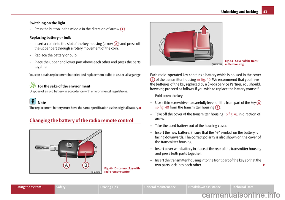
Each radio-operated key contains a battery which is housed in the cover
of the transmitter housing ⇒fig. 40 . We recommend that you have
the batteries of the key replaced by a Škoda Service Partner. You should,
however, proceed as follows if you wi sh to replace the battery yourself:
– Fold open the key.
– Use a thin screwdriver to carefully lever off the front part of the key ⇒fig. 40 from the transmitter housing .
– Take off the cover of the transmitter housing ⇒fig. 41 in direction of
arrow.
– Take the used battery out of the housing cover.
– Insert the new battery. Ensure that the “+” symbol on the battery is facing downwards. The correct polarity is also shown on the cover of
the transmitter housing.
– Insert cover with battery in place at the rear of the transmitter housing
and press both parts together.
– Insert the transmitter housing into the front part of the key so that the two parts lock into each other.
A1
A2
Fig. 40 Disconnect key with
radio remote control
Fig. 41 Cover of the trans-
mitter housing
AB
AA
AB
20A5Facelift.book Page 43 Saturday, September 6, 2008 2:13 PM
Page 61 of 304
Lights and Visibility
60
Daylight driving lights*
In some countries, the national legislation requires that the vehicles are
equipped with the function daylight driving lights.
Switching on daylight driving lights
– Switch on the ignition without turning the light switch out of the posi- tion 0.
Deactivate function daylight driving lights
– Pull the turn signal light lever towards the steering wheel up to 3 seconds after switching on the ignition and at the same time, slide it to
the bottom and hold it in this position for at least 3 seconds.
Activate function daylight driving lights
– Pull the turn signal light lever towards the steering wheel up to 3 seconds after switching on the ignition and at the same time, slide it to
the top and hold it in this position for at least 3 seconds.
When the daylight driving lights are switched on, the side lights and the low beam
shine together.
On vehicles which are fitted with bulbs for daylight driving lights* in the fog lights,
the parking lights do not switch on when activating the function daylight driving
lights.
When the daylight driving lights are switch ed on, the illumination of the instrument
cluster is switched off, however, it is switched on in the position
when it is dark
and the low beam shines with full br ightness (100 % of the performance).
On vehicles fitted with an information disp lay*, you can activate or deactivate in the
menu the function dayl ight driving lights:
„SETUP (Settings)
„Lights & Vision (Lights & Vision)
Automatic light control*
Switching on automatic light control*
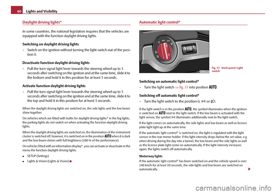
– Turn the light switch ⇒fig. 57 into position
.
Switching off automatic light control*
– Turn the light switch to the position 0,
or .
If the light switch is in the position , the symbol illuminates when the ignition
is switched on next to the light switch. If th e low beam is activated with the
light sensor, the symbol illuminates additionally next to the light switch.
If the light comes on automatically, the side lights and low beam as well as licence
plate light light up at the same time.
If the automatic light control* is switched on, the light is regulated with the light
sensor in the rear mirror holder. If the li ght intensity drops below the set value, e.g
when driving during the day into a tunnel, the low beam and the side lights as well
as the licence plate light co me on automatically. If the light intensity increases
again, the lights swit ch off automatically.
Motorway lights
If the automatic light control* has been sw itched on and the vehicle speed is over
140 km/h for at least 10 seconds, the sid e lights and low beam are switched on
automatically.
Fig. 57 Dash panel: Light
switch
20A5Facelift.book Page 60 Saturday, September 6, 2008 2:13 PM
Page 65 of 304
Lights and Visibility
64
Headlamp range adjustment
Once the low beam is switched on you can then adapt the range of
the headlights to the load of the vehicle.
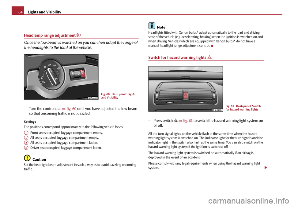
– Turn the control dial ⇒fig. 60 until you have adjusted the low beam
so that oncoming traffic is not dazzled.
Settings
The positions correspond approximat ely to the following vehicle loads:
Front seats occupied, lu ggage compartment empty.
All seats occupied, luggage compartment empty.
All seats occupied, luggage compartment laden.
Driver seat occupied, luggage compartment laden.
Caution
Set the headlight beam adjustment in su ch a way as to avoid dazzling oncoming
traffic.
Note
Headlights fitted with Xenon bulbs* adapt automatically to the load and driving
state of the vehicle (e.g. accelerating, braking) when the ignition is switched on and
when driving. Vehicles which are equi pped with Xenon bulbs* do not have a
manual headlight range adjustment control.
Switch for hazard warning lights
–Press switch ⇒ fig. 61 to switch the hazard warning light system on
or off.
All the turn signal lights on the vehicle flash at the same time when the hazard
warning light system is switched on. The indicator light for the turn signals and the
indicator light in the switch also flash at the same time. You can also switch on the
hazard warning light system if the ignition is switched off.
The hazard warning light system is switch ed on automatically if an airbag is
deployed in the event of an accident.
Please comply with any legal requirements when using the hazard warning light
system.
Fig. 60 Dash panel: Lights
and Visibility
A-
A1
A2
A3
Fig. 61 Dash panel: Switch
for hazard warning lights
20A5Facelift.book Page 64 Saturday, September 6, 2008 2:13 PM
Page 66 of 304
Lights and Visibility65
Using the systemSafetyDriving TipsGeneral MaintenanceBreakdown assistanceTechnical Data
Note
Switch on the hazard warning light system if, for example:
•you encounter traffic congestion,
•your vehicle breaks down or an emergency situation occurs.
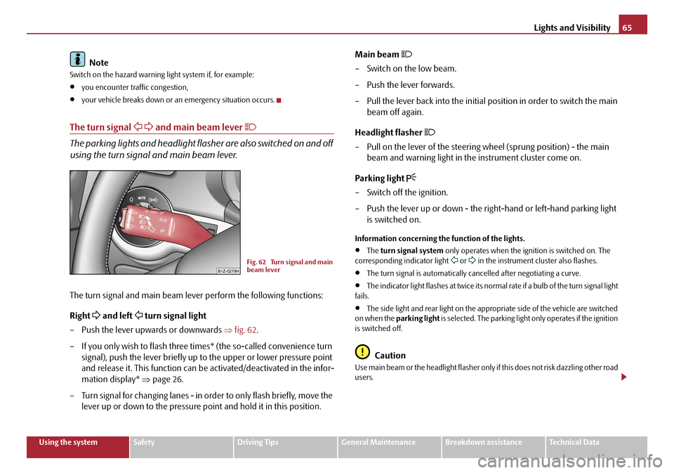
The turn signal and main beam lever
The parking lights and headlight flas her are also switched on and off
using the turn signal and main beam lever.
The turn signal and main beam lever perform the following functions:
Right
and left turn signal light
– Push the lever upwards or downwards ⇒fig. 62 .
– If you only wish to flash three times* (the so-called convenience turn signal), push the lever briefly up to the upper or lower pressure point
and release it. This function can be activated/deactivated in the infor-
mation display* ⇒page 26.
– Turn signal for changing lanes - in or der to only flash briefly, move the
lever up or down to the pressure po int and hold it in this position. Main beam
– Switch on the low beam.
– Push the lever forwards.
– Pull the lever back into the initial position in order to switch the main
beam off again.
Headlight flasher
– Pull on the lever of the steering wheel (sprung position) - the main beam and warning light in the instrument cluster come on.
Parking light
– Switch off the ignition.
– Push the lever up or down - the right-hand or left-hand parking light is switched on.
Information concerning the function of the lights.
•The turn signal system only operates when the ignition is switched on. The
corresponding indicator light or in the instrument cluster also flashes.
•The turn signal is automatically cancelled after negotiating a curve.
•The indicator light flashes at twice its normal rate if a bulb of the turn signal light
fails.
•The side light and rear light on the appropriate side of the vehicle are switched
on when the parking light is selected. The parking light only operates if the ignition
is switched off.
Caution
Use main beam or the headlight flasher only if this does not risk dazzling other road
users.
Fig. 62 Turn signal and main
beam lever
20A5Facelift.book Page 65 Saturday, September 6, 2008 2:13 PM
Page 67 of 304

Lights and Visibility
66
Note
•If you have switched on the right or left turn signal light and you switch off the
ignition, the parking light is not automatically switched on.
•Use only in accordance with the legal requirements the described lighting and
signal systems.
Interior lighting
Vehicle interior lighting front and rear*
The same principles apply for the lighti ng of the front and rear part of the
vehicle.
Switching the interior light on
– Press the switch to the left, the symbol
⇒ fig. 63 appears.
Switching the interior light off
– Press the switch into the middle position O.
– On the version without reading lights press the switch to the right, the symbol O appears. Door contact setting
– Press the switch to the right, the symbol
appears.
– On the version without reading lights press the switch into the middle position
.
Reading lights*
– Press on one of the switches in order to switch the right or left reading light on or off.
The interior light comes on as soon as yo u unlock the car or open a door or when
the ignition key has been removed. The light goes out again about 30 seconds after
all the doors have been closed. The interior lighting is switched off when you lock
the car or switch the ignition on. This on ly applies when the switch for the corre-
sponding interior lights is stan ding n the door contact setting.
The interior lighting goes off after about 10 minutes when a door has been left open
in order to avoid discharging the battery of the vehicle.
If the switch is in the position
(permanent lights), the interior lighting goes off at
the latest after 10 minutes in order to avoid discharging the battery of the vehicle.
Note
We recommend having these bulbs re placed by a specialist garage.
Lighting of the storage compartment on front passenger side*
– When opening the flap of the storage compartment on the front
passenger side the lighting in the storage compartment comes on.
– The light switches on automatically when the parking light is switched
on and goes out when the flap is closed.
Fig. 63 Detail of the head-
liner: Front and rear interior
lighting
AA
AA
AA
AA
AA
AB
20A5Facelift.book Page 66 Saturday, September 6, 2008 2:13 PM
Page 234 of 304

Inspecting and replenishing233
Using the systemSafetyDriving TipsGeneral MaintenanceBreakdown assistanceTechnical Data
•Hydrogen is released when you char ge a battery and a highly explosive
gas mixture is produced. An explosion can be caused through sparkling over
during unclamping or loosening of the cable plug while the ignition is on.
•Bridging of the poles will create a short circuit (e.g. through metal
objects, cables). Possible consequences of a short circuit: Melting of lead
struts, explosion and burning of the battery, jets of acid spurting out.
•It is prohibited to work with a naked flame and light, to smoke or to carry
out any activities which produce sparks. Avoid creating sparks when
working with cables and electrical device s. Strong sparking represents a risk
of injury.
•Before carrying out any work on the electrical system, switch off the
engine, the ignition as well as all electrical components and disconnect the
negative cable (-) on the battery. If you wish to replace a bulb it is sufficient
to switch off the appropriate light.
•Never charge a frozen or thawed battery - risk of explosion and caustic
burns! Replace a frozen battery.
•Never use a battery which is damaged - risk of explosion! Immediately
replace a damaged battery.
Caution
•You must only disconnect the battery if the ignition is switched off, otherwise
the electrical system (electronic compon ents) of the vehicle may be damaged.
When disconnecting the battery from the electrical system of the vehicle, first
disconnect the negative terminal (-) of the battery. Then disconnect the positive
terminal (+).
•When reconnecting the battery, first conne ct the positive terminal (+) and only
then the negative terminal (-) of the ba ttery. You must on no account connect the
cables wrongly - risk of a cable fire.
•Ensure that battery acid does not come into contact with the vehicle body
otherwise damage could occur to the paintwork.
•Do not place the battery in direct dayl ight in order to protect the battery
housing from the effects of ultra-violet light.
For the sake of the environment
A removed battery is a special type of waste which is harmful to the environment -
contact your specialist garage regarding disposing of the battery.
Note
Please also refer to the guidelines ⇒page 235, also after connecting the battery.
Battery with a charge level indicator, the so-called magic eye
There is a so-called magic eye ⇒fig. 216 located on the top of the battery. The
“magic eye” changes its colour in line with the charge state of and electrolyte level
in the battery.
Air bubbles can influence the colour of th e “magic eye”. For this reason carefully
knock on the “magic eye” before carrying out the check.
•Green colour - the battery is adequately charged.
•Dark colour - the battery has to be charged
•Colourless or yellow colour - have th e battery checked by a Škoda dealer.
Batteries, which are more than 5 years old, must be replaced. We recommend you
have the electrolyte level inspected and adju sted to the correct level or the battery
replaced if necessary by a Škoda Service Partner.
WARNING (continued)
Fig. 216 Battery with a
charge level indicator
20A5Facelift.book Page 233 Saturday, September 6, 2008 2:13 PM
Page 258 of 304
Fuses and light bulbs257
Using the systemSafetyDriving TipsGeneral MaintenanceBreakdown assistanceTechnical Data
Fuses and light bulbs
Electric fuses
Replacing fuses
Defect fuses must be replaced.
Individual electrical circuits are protected by fuses. The fuses are located
on the left side of the dash panel behind the safety cover and under the
cover in the engine compartment on the left.
– Switch the ignition off and also the electrical component affected.
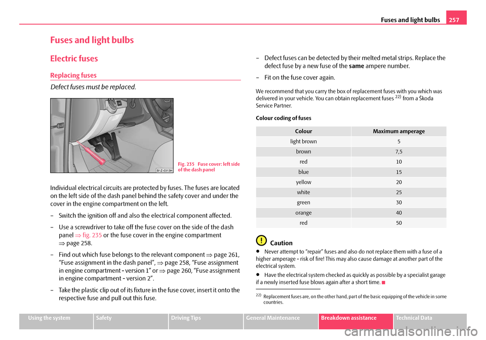
– Use a screwdriver to take off the fuse cover on the side of the dash panel ⇒fig. 235 or the fuse cover in the engine compartment
⇒ page 258.
– Find out which fuse belongs to the relevant component ⇒page 261,
“Fuse assignment in the dash panel”, ⇒page 258, “Fuse assignment
in engine compartment - version 1” or ⇒page 260, “Fuse assignment
in engine compartment - version 2”.
– Take the plastic clip out of its fixture in the fuse cover, insert it onto the respective fuse and pull out this fuse. – Defect fuses can be detected by their melted metal strips. Replace the
defect fuse by a new fuse of the same ampere number.
– Fit on the fuse cover again.
We recommend that you carry the box of replacement fuses with you which was
delivered in your vehicle. You can obtain replacement fuses 22) from a Škoda
Service Partner.
Colour coding of fuses
Caution
•Never attempt to “repair” fuses and also do not replace them with a fuse of a
higher amperage - risk of fire! This may also cause damage at another part of the
electrical system.
•Have the electrical system checked as quickly as possible by a specialist garage
if a newly inserted fuse blows again after a short time.
Fig. 235 Fuse cover: left side
of the dash panel
22)Replacement fuses are, on the other hand, part of the basic equipping of the vehicle in some
countries.
ColourMaximum amperage
light brown5
brown7,5
red10
blue15
yellow20
white25
green30
orange40
red50
20A5Facelift.book Page 257 Saturday, September 6, 2008 2:13 PM