key battery SKODA OCTAVIA 2009 2.G / (1Z) Owner's Manual
[x] Cancel search | Manufacturer: SKODA, Model Year: 2009, Model line: OCTAVIA, Model: SKODA OCTAVIA 2009 2.G / (1Z)Pages: 304, PDF Size: 19.56 MB
Page 4 of 304
Contents3
Using the system
Safety
Driving Tips
General Maintenance
Breakdown assistance
Technical Data
ContentsLayout of this Owner's Manual
(explanations)
. . . . . . . . . . . . . . . . . . . . . . . . . .
Using the system
. . . . . . . . . . . . . . . . . . . . . .
Cockpit
. . . . . . . . . . . . . . . . . . . . . . . . . . . . . . . . . . . . . . . .
Overview . . . . . . . . . . . . . . . . . . . . . . . . . . . . . . . . . . . .
The brief instruction
. . . . . . . . . . . . . . . . . . . . . . . . . .
Basic functions and important information . . . . .
Instruments and Indicator/Warning Lights
. . .
General view of the instrument cluster . . . . . . . . .
Engine revolutions counter . . . . . . . . . . . . . . . . . . . .
Speedometer . . . . . . . . . . . . . . . . . . . . . . . . . . . . . . . .
Coolant temperature gauge . . . . . . . . . . . . . . . . . . .
Fuel gauge . . . . . . . . . . . . . . . . . . . . . . . . . . . . . . . . . . .
Counter for distance driven . . . . . . . . . . . . . . . . . . .
Service Interval Display . . . . . . . . . . . . . . . . . . . . . . .
Digital clock . . . . . . . . . . . . . . . . . . . . . . . . . . . . . . . . . .
Multi-functional indicator (onboard computer)*
Information display* . . . . . . . . . . . . . . . . . . . . . . . . . .
Auto Check Control* . . . . . . . . . . . . . . . . . . . . . . . . . .
Warning lights . . . . . . . . . . . . . . . . . . . . . . . . . . . . . . . .
Unlocking and locking
. . . . . . . . . . . . . . . . . . . . . . . .
Key . . . . . . . . . . . . . . . . . . . . . . . . . . . . . . . . . . . . . . . . . .
Changing the battery of the radio remote control
Electronic immobiliser . . . . . . . . . . . . . . . . . . . . . . . .
Child safety lock . . . . . . . . . . . . . . . . . . . . . . . . . . . . . .
Central locking system . . . . . . . . . . . . . . . . . . . . . . . .
Remote control* . . . . . . . . . . . . . . . . . . . . . . . . . . . . . .
Synchonisation of the remote control . . . . . . . . . .
Anti-theft alarm system* . . . . . . . . . . . . . . . . . . . . . . Power windows* . . . . . . . . . . . . . . . . . . . . . . . . . . . . .
Electric sliding/tilting roof* . . . . . . . . . . . . . . . . . . . .
Lights and Visibility
. . . . . . . . . . . . . . . . . . . . . . . . . . .
Lights . . . . . . . . . . . . . . . . . . . . . . . . . . . . . . . . . . . . . . . .
Interior lighting . . . . . . . . . . . . . . . . . . . . . . . . . . . . . . .
Visibility . . . . . . . . . . . . . . . . . . . . . . . . . . . . . . . . . . . . .
Windshield wiper and wash system . . . . . . . . . . . .
Rear-view mirror . . . . . . . . . . . . . . . . . . . . . . . . . . . . .
Seats and Stowage
. . . . . . . . . . . . . . . . . . . . . . . . . . . .
Front seats . . . . . . . . . . . . . . . . . . . . . . . . . . . . . . . . . . .
Adjusting front seats electrically* . . . . . . . . . . . . . .
Head restraints . . . . . . . . . . . . . . . . . . . . . . . . . . . . . . .
Middle rear head restraint . . . . . . . . . . . . . . . . . . . . .
Rear seats . . . . . . . . . . . . . . . . . . . . . . . . . . . . . . . . . . . .
Pedals . . . . . . . . . . . . . . . . . . . . . . . . . . . . . . . . . . . . . . .
luggage compartment . . . . . . . . . . . . . . . . . . . . . . . .
Net partition (Combi)* . . . . . . . . . . . . . . . . . . . . . . . .
The roof rack* . . . . . . . . . . . . . . . . . . . . . . . . . . . . . . . .
Cup holder . . . . . . . . . . . . . . . . . . . . . . . . . . . . . . . . . . .
Note holder . . . . . . . . . . . . . . . . . . . . . . . . . . . . . . . . . .
Ashtray* . . . . . . . . . . . . . . . . . . . . . . . . . . . . . . . . . . . . .
Cigarette lighter*, power sockets . . . . . . . . . . . . . . .
Storage compartments . . . . . . . . . . . . . . . . . . . . . . . .
Overview . . . . . . . . . . . . . . . . . . . . . . . . . . . . . . . . . . . .
Storage compartment on the front passenger side
Cooling of storage compartment on front
passenger side* . . . . . . . . . . . . . . . . . . . . . . . . . . . . . .
Storage compartment on the driver's side . . . . . .
Storage compartment on the dash panel* . . . . . .
Storage compartment in front centre console* . .
Storage net on the front centre console* . . . . . . .
Storage compartment for spectacles* . . . . . . . . . .
Storage compartment in the front doors . . . . . . . . Storage compartment below front passenger
seat* . . . . . . . . . . . . . . . . . . . . . . . . . . . . . . . . . . . . . . . .
Front seat armrest with storage compartment* .
Rear seat armrest with storage compartment* . .
Storage compartment in rear centre console* . .
Seat backrest with opening for skis* . . . . . . . . . . . .
Through-loading bag (Unibag)* . . . . . . . . . . . . . . .
Side compartment* . . . . . . . . . . . . . . . . . . . . . . . . . .
Storage compartment behind the rear seats*
(Combi) . . . . . . . . . . . . . . . . . . . . . . . . . . . . . . . . . . . . .
Clothes hooks* . . . . . . . . . . . . . . . . . . . . . . . . . . . . . .
Heating and air conditioning system
. . . . . . . . .
Air outlet vents . . . . . . . . . . . . . . . . . . . . . . . . . . . . . . .
Heating . . . . . . . . . . . . . . . . . . . . . . . . . . . . . . . . . . . . . .
Climatic* (semi-automatic air conditioning
system) . . . . . . . . . . . . . . . . . . . . . . . . . . . . . . . . . . . . . .
Climatronic* (automatic air conditioning) . . . . . .
Auxiliary heating (auxiliary heating and
ventilation)* . . . . . . . . . . . . . . . . . . . . . . . . . . . . . . . . .
Starting-off and Driving
. . . . . . . . . . . . . . . . . . . . . .
Setting steering wheel position . . . . . . . . . . . . . . . .
Ignition lock . . . . . . . . . . . . . . . . . . . . . . . . . . . . . . . . .
Starting the engine . . . . . . . . . . . . . . . . . . . . . . . . . . .
Switching off the engine . . . . . . . . . . . . . . . . . . . . . .
Shifting (manual gearbox) . . . . . . . . . . . . . . . . . . . . .
Handbrake . . . . . . . . . . . . . . . . . . . . . . . . . . . . . . . . . . .
Rear parking aid* . . . . . . . . . . . . . . . . . . . . . . . . . . . . .
Front and rear parking aid* . . . . . . . . . . . . . . . . . . . .
Cruise control system (CCS)* . . . . . . . . . . . . . . . . . .
Automatic gearbox
. . . . . . . . . . . . . . . . . . . . . . . . . . .
Automatic gearbox* . . . . . . . . . . . . . . . . . . . . . . . . . . 6
7
9
9
11
11
17
17
18
18
18
18
19
20
21
21
26
28
31
42
42
42
43
44
44
49
50
5152
55
58
58
65
67
69
72
75
75
76
79
80
81
84
84
91
93
95
96
96
98
99
99
99
100
100
101
101
101
102
102103
103
104
104
105
105
106
107
107
108
108
109
111
115
119
122
122
123
124
125
125
126
127
128
129
132
132
se0.1.book Page 3 Friday, April 10, 2009 3:19 PM
Page 21 of 304
Instruments and Indicator/Warning Lights
20
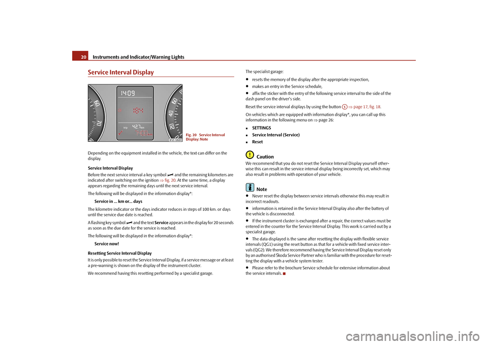
Service Interval DisplayDepending on the equipment installed in the vehicle, the text can differ on the display. Service Interval Display Before the next service interval a key symbol
and the remaining kilometers are
indicated after switching on the ignition
⇒fig. 20
. At the same time, a display
appears regarding the remaining days until the next service interval. The following will be displayed in the information display*:
Service in ... km or... days
The kilometre indicator or the days indica
tor reduces in steps of 100 km. or days
until the service due date is reached. A flashing key symbol
and the text
Service
appears in the display for 20 seconds
as soon as the due date for the service is reached. The following will be displayed in the information display*:
Service now!
Resetting Service Interval Display It is only possible to reset the Service Interval Display, if a service message or at least a pre-warning is shown on the display of the instrument cluster. We recommend having this resetting
performed by a specialist garage.
The specialist garage:•
resets the memory of the display after the appropriate inspection,
•
makes an entry in the Service schedule,
•
affix the sticker with the entry of the following service interval to the side of the
dash panel on the driver's side. Reset the service interval displays by using the button
⇒page 17, fig. 18
.
On vehicles which are equipped with in
formation display*, you can call up this
information in the following menu on
⇒page 26:
�„
SETTINGS
�„
Service Interval (Service)
�„
ResetCaution
We recommend that you do not reset the
Service Interval Disp
lay yourself other-
wise this can result in the service interval display being incorrectly set, which may also result in problems with
operation of your vehicle.
Note
•
Never reset the display between service intervals otherwise this may result in
incorrect readouts.•
information is retained in the Service Interval Display also after the battery of
the vehicle is disconnected.•
If the instrument cluster is exchanged afte
r a repair, the correct values must be
entered in the counter for the Service Interva
l Display. This work is carried out by a
specialist garage.•
The data displayed is the same after resetting the display with flexible service
intervals (QG1) using the reset button as th
at for a vehicle with fixed service inter-
vals (QG2). We therefore recommend having
the Service Interval Display reset only
by an authorised Škoda Service Partner who is familiar with the procedure for reset- ting the display with a vehicle system tester.•
Please refer to the brochure Service schedule for extensive information about
the service intervals.
Fig. 20 Service Interval Display: Note
A5
se0.1.book Page 20 Friday, April 10, 2009 3:19 PM
Page 43 of 304
Unlocking and locking
42
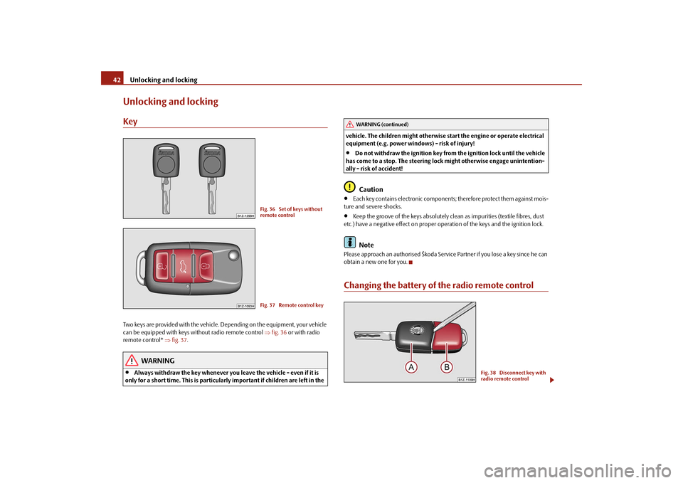
Unlocking and lockingKeyTwo keys are provided with the vehicle. Depending on the equipment, your vehicle can be equipped with keys wi
thout radio remote control
⇒fig. 36
or with radio
remote control*
⇒fig. 37
.
WARNING
•
Always withdraw the key
whenever you leave the vehicle - even if it is
only for a short time. This is particularly important if children are left in the
vehicle. The children might otherwise st
art the engine or
operate electrical
equipment (e.g. power windows) - risk of injury!•
Do not withdraw the ignition key from the ignition lock until the vehicle
has come to a stop. The steering lock
might otherwise engage unintention-
ally - risk of accident!
Caution
•
Each key contains electronic components; therefore protect them against mois-
ture and severe shocks.•
Keep the groove of the keys absolutely cl
ean as impurities (t
extile fibres, dust
etc.) have a negative effect on proper op
eration of the keys and the ignition lock.
Note
Please approach an authorised Škoda Service Partner if you lose a key since he can obtain a new one for you.Changing the battery of the radio remote control
Fig. 36 Set of keys without remote controlFig. 37 Remote control key
WARNING (continued)
Fig. 38 Disconnect key with radio remote control
se0.1.book Page 42 Friday, April 10, 2009 3:19 PM
Page 44 of 304
Unlocking and locking
43
Using the system
Safety
Driving Tips
General Maintenance
Breakdown assistance
Technical Data
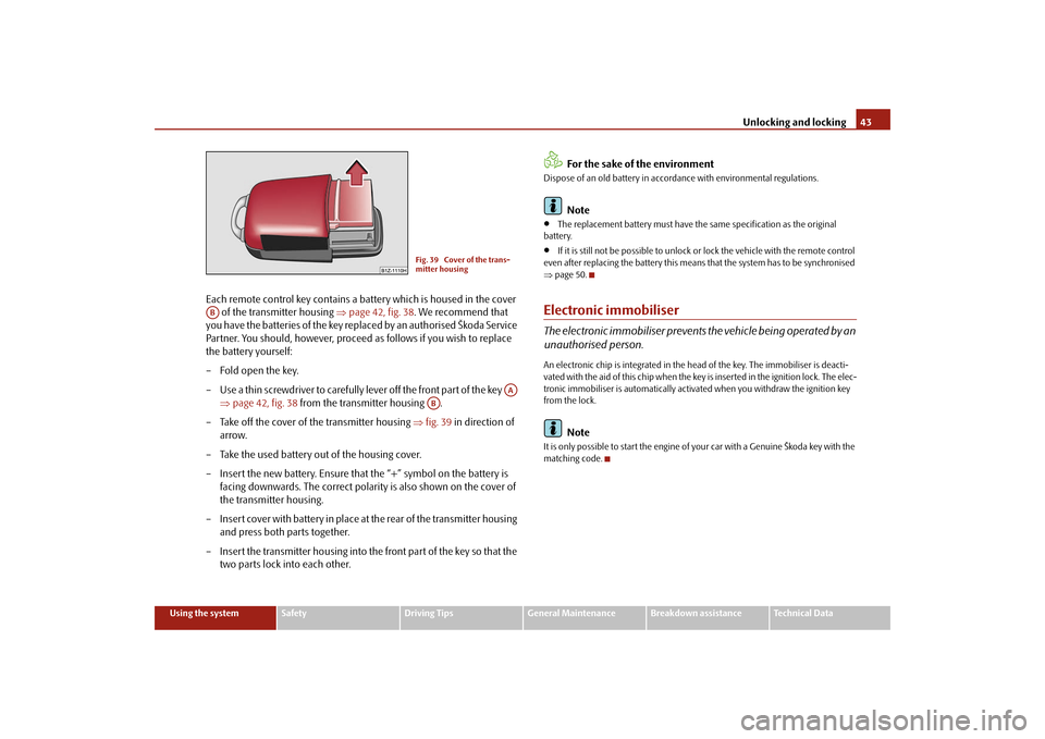
Each remote control key contains a battery which is housed in the cover
of the transmitter housing
⇒
page 42, fig. 38
. We recommend that
you have the batteries of the key repl
aced by an authorised Škoda Service
Partner. You should, however, proceed as follows if you wish to replace the battery yourself: – Fold open the key. – Use a thin screwdriver to carefully
lever off the front part of the key
⇒
page 42, fig. 38
from the transmitter housing .
– Take off the cover of the transmitter housing
⇒
fig. 39
in direction of
arrow.
– Take the used battery out of the housing cover. – Insert the new battery. Ensure that the “+” symbol on the battery is
facing downwards. The correct polarity is also shown on the cover of the transmitter housing.
– Insert cover with battery in place at the rear of the transmitter housing
and press both parts together.
– Insert the transmitter housing into th
e front part of the key so that the
two parts lock into each other.
For the sake of the environment
Dispose of an old battery in accord
ance with environmental regulations.
Note
•
The replacement battery must have the same specification as the original
battery.•
If it is still not be possible to unlock or
lock the vehicle with the remote control
even after replacing the battery this means
that the system has to be synchronised
⇒ page 50.Electronic immobiliserThe electronic immobiliser prevents
the vehicle being operated by an
unauthorised person.An electronic chip is integrated in the he
ad of the key. The immobiliser is deacti-
vated with the aid of this chip when the key
is inserted in the ignition lock. The elec-
tronic immobiliser is automatically activa
ted when you withdraw the ignition key
from the lock.
Note
It is only possible to start the engine of
your car with a Genui
ne Škoda key with the
matching code.
Fig. 39 Cover of the trans- mitter housing
AB
AA
AB
se0.1.book Page 43 Friday, April 10, 2009 3:19 PM
Page 50 of 304
Unlocking and locking
49
Using the system
Safety
Driving Tips
General Maintenance
Breakdown assistance
Technical Data
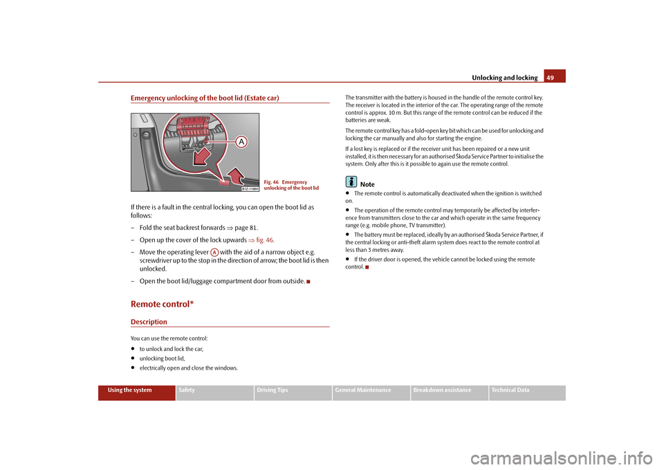
Emergency unlocking of the boot lid (Estate car)If there is a fault in the central lo
cking, you can open the boot lid as
follows: – Fold the seat backrest forwards
⇒
page 81.
– Open up the cover of the lock upwards
⇒
fig. 46
.
– Move the operating lever with th
e aid of a narrow object e.g.
screwdriver up to the stop in the direction of arrow; the boot lid is then unlocked.
– Open the boot lid/luggage compartment door from outside.Remote control*DescriptionYou can use the remote control:•
to unlock and lock the car,
•
unlocking boot lid,
•
electrically open and close the windows.
The transmitter with the battery is housed in the handle of the remote control key. The receiver is located in the interior of
the car. The operating range of the remote
control is approx. 10 m. But this range of
the remote control can be reduced if the
batteries are weak. The remote control key has a fold-open key
bit which can be used for unlocking and
locking the car manually and also for starting the engine. If a lost key is replaced or if the receiv
er unit has been repaired or a new unit
installed, it is then necessary for an authorised Škoda Service Partner to initialise the system. Only after this is it possib
le to again use the remote control.
Note
•
The remote control is automatically deac
tivated when the ignition is switched
on.•
The operation of the remote control may temporarily be affected by interfer-
ence from transmitters close to the car and which operate in the same frequency range (e.g. mobile phone, TV transmitter).•
The battery must be replaced, ideally by
an authorised Škoda Service Partner, if
the central locking or anti-theft alarm system does react to the remote control at less than 3 metres away.•
If the driver door is opened, the vehicle cannot be locked using the remote
control.
Fig. 46 Emergency unlocking of the boot lid
AA
se0.1.book Page 49 Friday, April 10, 2009 3:19 PM
Page 51 of 304
Unlocking and locking
50
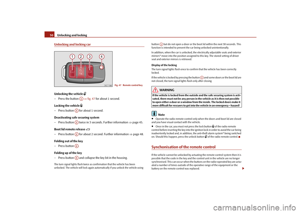
Unlocking and locking carUnlocking the vehicle
– Press the button
⇒
fig. 47
for about 1 second.
Locking the vehicle
– Press button for about 1 second.Deactivating safe securing system – Press button twice in 3 seconds. Further information
⇒
page 45.
Boot lid remote release
– Press button for about 2 second. Further information
⇒
page 48.
Folding out of the key – Press button . Folding up of the key – Press button and collapse the key bit in the housing.The turn signal lights flash twice as
confirmation that the vehicle has been
unlocked. The vehicle will lock again auto
matically if you unlock the vehicle using
button but do not open a door or the b
oot lid within the next 30 seconds. This
function is intended to prevent the car being unlocked unintentionally. In addition, when the car is unlocked, the el
ectrically adjustable seats and exterior
mirrors* move into the position assigned to this key. The stored setting of driver seat and exterior mirrors is retrieved. Display of the locking The turn signal lights flash once to co
nfirm that the vehicle has been correctly
locked. If the vehicle is locked by
pressing the button and some doors or the boot lid are
not closed, the turn signal lights flash only after closing.
WARNING
If the vehicle is locked from the outsid
e and the safe securing system is acti-
vated, there must not be any person in the vehicle as it is then not possible to open either a door or a window from the inside. The locked doors make it more difficult for rescuers to get into
the vehicle in an emergency - hazard!
Note
•
Operate the radio remote control only when the doors and boot lid are closed
and you have visual co
ntact with the vehicle.
•
Once in the car, you must
not press the lock button
of the radio remote
control before inserting the key into the ignition lock in order to avoid the car being inadvertently locked and, in addition, the anti-theft alarm system* being switched on. Should this happen, press the unlock button
of the radio remote control.
Synchonisation of the remote controlIf the vehicle cannot be unlocked by actuatin
g the remote control system then it is
possible that the code in the key and the
control unit in the vehicle are no longer
synchronised. This can occur when the buttons on the radio-operated key are actu- ated a number of times outside of the operative range of the equipment or the battery on the remote control was replaced.
Fig. 47 Remote control key
A1
A3A2A2A4A4
A1
A3
se0.1.book Page 50 Friday, April 10, 2009 3:19 PM
Page 52 of 304
Unlocking and locking
51
Using the system
Safety
Driving Tips
General Maintenance
Breakdown assistance
Technical Data
This means it is necessary to synchronise the code as follows:•
Press any button on the remote control.
•
Pressing of the button means that the
door will unlock with the key within 1
minute.Anti-theft alarm system*DescriptionThe anti-theft alarm system increases the le
vel of protection against people seeking
to break into the vehicle. The system tri
ggers audible and visual warning signals if
an attempt is made to break into the vehicle. How is the alarm system activated? The anti-theft alarm system is activated
automatically when th
e vehicle is locked
with the key on the closed driver's door or
by using the radio remote control. It is
activated 30 seconds after closing the door. How is the alarm system deactivated? The anti-theft alarm system is deactivated
if the vehicle is unlocked by only using
the radio remote control. The vehicle is au
tomatically locked agai
n if the vehicle is
not opened within 30 seconds after reac
tivating the anti-theft alarm system.
Once you unlock the vehicle by inserting the key into the driver door you then have to insert the key into the ignition lock an
d switch the ignition on within 15 seconds
after opening the door in order to deactivate the anti-theft alarm system. The alarm will be triggered
if you do
not switch on
the ignition within 15 seconds.
When is the alarm triggered? The following security areas of the locked vehicle are monitored:•
Bonnet,
•
Boot lid,
•
Doors,
•
Ignition lock,
•
Angle of the vehicle*
⇒page 51,
•
Vehicle interior*
⇒page 51,
•
A drop in voltage of the on-board power supply.
An alarm is immediately triggered if either of the two battery terminals is discon- nected while the anti-theft
alarm system is activated.
How is the alarm switched off? You switch the alarm off if you unlock the car with the radio remote control in the key or if you switch the ignition on.
Note
•
The working life of the alarm siren is 6 years. More detailed information is avail-
able by a specialist garage.•
Before leaving the car, check that all the doors, windows and the electric
sliding/tilting roof* are properly closed in order to ensure that the anti-theft alarm system is fully operational.•
Coding of the radio remote control and
the receptor part precludes the use of
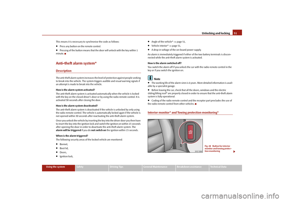
the radio remote control from other vehicles.Interior monitor* and Towing protection monitoring*
Fig. 48 Button for interior monitor and towing protec-tion monitoring
se0.1.book Page 51 Friday, April 10, 2009 3:19 PM
Page 56 of 304

Unlocking and locking
55
Using the system
Safety
Driving Tips
General Maintenance
Breakdown assistance
Technical Data
may otherwise suffer severe injuries
as a result of getting an arm, for
example, jammed in the window!
Note
On vehicles fitted with anti-theft alarm
system the convenience window opening is
possible by means of the key in the lock
ing cylinder only 45 seconds after deacti-
vating the warning system or after ac
tivating the anti-theft alarm system.
Operational faultsElectrically operated power windows do not operate If the battery of the car has been discon
nected and then reconnected, the electri-
cally operated power windows do not oper
ate. The system must be activated.
Proceed as follows in order to re-establish the function:•
Switch on the ignition.
•
Press the relevant switch
top
and hold it pressed as lo
ng as necessary until the
window is closed.•
Release the switch.
•
Press once again the relevant switch
top
and hold it pressed for approx. 3
seconds. Operation in winter Ice accumulating on the surface of the wi
ndows during the winter may result in a
greater resistance when closing the windows and the window may stop and go down several centimetres It is necessary to put the force limiter out of operation in order to close the window ⇒ page 54, “Force limiter of the power windows”.
WARNING
The system is fitted with a force limiter
⇒page 54. If there is an obstacle, the
closing process is stopped and the wi
ndow goes down by several centime-
ters. You should then take particular care when closing the windows! You may otherwise suffer severe injuries as a result of getting an arm, for example, jammed in the window!Electric sliding/tilting roof*DescriptionThe sliding/tilting roof is operated by means of the control dial
⇒fig. 51
and only
functions when the ignition is switched on
. The control dial has a number of fixed
positions. After switching the ignition off, it is still possible to open or close the sliding/tilting roof for a further 10 minutes. It is no long
er possible to operate the sliding/tilting
roof after opening or closing on
e of the front doors, however.
Note
If the battery has been disconnected and reconnected, it is possible that the sliding/tilting roof does not close fully. Here you have to set the control dial to the switch position and press it
forward for about 10 seconds.
WARNING (continued)
WARNING (continued)
Fig. 51 Control dial for the power sliding/tilting roof
AA
se0.1.book Page 55 Friday, April 10, 2009 3:19 PM
Page 67 of 304

Lights and Visibility
66
Reading lights* – Press on one of the switches in order to switch the right or left
reading light on or off.
The interior light comes on as soon as you unlock the car or open a door or when the ignition key has been removed. The li
ght goes out again about 30 seconds after
all the doors have been closed. The interior
lighting is switched off when you lock
the car or switch the ignition on. This on
ly applies when the switch for the corre-
sponding interior lights is stan
ding n the door contact setting.
The interior lighting goes off after about
10 minutes when a door has been left open
in order to avoid discharging the battery of the vehicle. If the switch is in the position
(permanent lights), the interior lighting goes off at
the latest after 10 minutes in order to avoid discharging the battery of the vehicle.
Note
We recommend having these bulbs re
placed by a specialist garage.
Lighting of the storage compartment on front passenger side*– When opening the flap of the st
orage compartment on the front
passenger side the lighting in the storage compartment comes on.
– The light switches on automatically
when the parking light is switched
on and goes out when the flap is closed.
Front door warning light*The warning light is located in the door trim panel below
⇒fig. 62
.
The warning light goes on every time the door is opened. The light goes out about 10 minutes after opening the d
oor in order to avoid discharging the battery of the
vehicle. There is a reflector installed on some vehicles instead of the warning light.Luggage compartment light*The lighting comes on automatically when
the boot lid is opened. The luggage
compartment lighting will switch off agai
n automatically if the boot lid remains
open for more than about 30 minutes.Entry lighting*The lighting is positioned on the bottom edge of the exterior mirror. The light beam is directed towards the entry area of the front door.The light comes on after the doors have been
locked or on opening the boot lid. The
light goes out after switching on the ignition
or up to 30 seconds after closing all the
doors, the bonnet and the boot lid.
AB
Fig. 62 Front door: Warning light
se0.1.book Page 66 Friday, April 10, 2009 3:19 PM
Page 99 of 304

Seats and Stowage
98
Cigarette lighter*, power socketsCigarette lighter You can also use the socket on the cigarette lighter for other elec- trical appliances.Using the cigarette lighter – Press in the button of the cigarette lighter
⇒
fig. 116
.
– Wait until the button jumps forward. – Remove the cigarette lighter immediately and use it.– Insert the cigarette lighter again into the socket. Using the socket – Remove the cigarette lighter or the cover of the power socket. – Connect the plug of the electr
ical appliance to the socket.
The 12 volt power socket can also be used
to supply power to electrical accessories
with a power uptake up to 180 watts.
WARNING
•
Take care when using the cigarette li
ghter! Not paying proper attention
or incorrect use the cigarette lighter in
an uncontrolled manner may result in
burns.•
The cigarette lighter and the power so
cket also operates when the igni-
tion is switched off or the ignition key withdrawn. You should therefore never leave children unattended in the vehicle.
Caution
Always use matching
plugs to avoid damagi
ng the power socket.
Note
•
Connecting electrical components when the engine is not running will
drain the battery of the vehicl
e - risk of battery draining!
•
Further information
⇒page 244, “Accessories, changes and replacement of
parts”.Power socket in the luggage compartment (Combi)– Open the cover of the power socket
⇒
fig. 117
.
Fig. 116 Centre console: Cigarette lighter
Fig. 117 Luggage compart-ment: Power socket
se0.1.book Page 98 Friday, April 10, 2009 3:19 PM