key SKODA OCTAVIA 2010 2.G / (1Z) Owner's Manual
[x] Cancel search | Manufacturer: SKODA, Model Year: 2010, Model line: OCTAVIA, Model: SKODA OCTAVIA 2010 2.G / (1Z)Pages: 275, PDF Size: 16.43 MB
Page 4 of 275
Contents3
Using the system
Safety
Driving Tips
General Maintenance
Breakdown assistance
Technical Data
ContentsLayout of this Owner's Manual
(explanations)
. . . . . . . . . . . . . . . . . . . . . . . . . .
Using the system
. . . . . . . . . . . . . . . . . . . . . .
Cockpit
. . . . . . . . . . . . . . . . . . . . . . . . . . . . . . . . . . . . . . . .
Overview . . . . . . . . . . . . . . . . . . . . . . . . . . . . . . . . . . . .
The brief instruction
. . . . . . . . . . . . . . . . . . . . . . . . . .
Basic functions and important information . . . . .
Instruments and warning lights
. . . . . . . . . . . . . . .
Overview of the instrument cluster . . . . . . . . . . . . .
Engine revolutions counter . . . . . . . . . . . . . . . . . . . .
Speedometer . . . . . . . . . . . . . . . . . . . . . . . . . . . . . . . .
Coolant temperature gauge . . . . . . . . . . . . . . . . . . .
Fuel gauge . . . . . . . . . . . . . . . . . . . . . . . . . . . . . . . . . . .
Counter for distance driven . . . . . . . . . . . . . . . . . . .
Service Interval Display . . . . . . . . . . . . . . . . . . . . . . .
Digital clock . . . . . . . . . . . . . . . . . . . . . . . . . . . . . . . . . .
Shift recommendation for changing gears* . . . . .
Multi-functional indicator (onboard computer)*
Information display* . . . . . . . . . . . . . . . . . . . . . . . . . .
Auto Check Control* . . . . . . . . . . . . . . . . . . . . . . . . . .
Warning lights . . . . . . . . . . . . . . . . . . . . . . . . . . . . . . . .
Unlocking and locking
. . . . . . . . . . . . . . . . . . . . . . . .
Key . . . . . . . . . . . . . . . . . . . . . . . . . . . . . . . . . . . . . . . . . .
Changing the battery of the radio remote control
Electronic immobiliser . . . . . . . . . . . . . . . . . . . . . . . .
Child safety lock . . . . . . . . . . . . . . . . . . . . . . . . . . . . . .
Central locking system . . . . . . . . . . . . . . . . . . . . . . . .
Remote control* . . . . . . . . . . . . . . . . . . . . . . . . . . . . . .
Syncronisation of the remote control . . . . . . . . . . .
Anti-theft alarm system* . . . . . . . . . . . . . . . . . . . . . .
Power windows* . . . . . . . . . . . . . . . . . . . . . . . . . . . . .
Electric sliding/tilting roof* . . . . . . . . . . . . . . . . . . . .
Lights and Visibility
. . . . . . . . . . . . . . . . . . . . . . . . . . . .
Lights . . . . . . . . . . . . . . . . . . . . . . . . . . . . . . . . . . . . . . . .
Interior lighting . . . . . . . . . . . . . . . . . . . . . . . . . . . . . . .
Visibility . . . . . . . . . . . . . . . . . . . . . . . . . . . . . . . . . . . . . .
Windshield wiper and wash system . . . . . . . . . . . . .
Rear-view mirror . . . . . . . . . . . . . . . . . . . . . . . . . . . . . .
Seats and Stowage
. . . . . . . . . . . . . . . . . . . . . . . . . . . . .
Front seats . . . . . . . . . . . . . . . . . . . . . . . . . . . . . . . . . . . .
Adjusting front seats electrically* . . . . . . . . . . . . . . .
Head restraints . . . . . . . . . . . . . . . . . . . . . . . . . . . . . . . .
Middle rear head restraint . . . . . . . . . . . . . . . . . . . . .
Rear seats . . . . . . . . . . . . . . . . . . . . . . . . . . . . . . . . . . . .
Pedals . . . . . . . . . . . . . . . . . . . . . . . . . . . . . . . . . . . . . . . .
luggage compartment . . . . . . . . . . . . . . . . . . . . . . . . .
Luggage net partition* (Combi) . . . . . . . . . . . . . . . .
The roof rack* . . . . . . . . . . . . . . . . . . . . . . . . . . . . . . . .
Cup holder . . . . . . . . . . . . . . . . . . . . . . . . . . . . . . . . . . .
Note holder . . . . . . . . . . . . . . . . . . . . . . . . . . . . . . . . . .
Ashtray* . . . . . . . . . . . . . . . . . . . . . . . . . . . . . . . . . . . . . .
Cigarette lighter*, power sockets . . . . . . . . . . . . . . .
Storage compartments . . . . . . . . . . . . . . . . . . . . . . . .
Overview . . . . . . . . . . . . . . . . . . . . . . . . . . . . . . . . . . . . .
Storage compartment on the front passenger side
Cooling of storage compartment on front passenger
side* . . . . . . . . . . . . . . . . . . . . . . . . . . . . . . . . . . . . . . . . .
Storage compartment on the driver's side . . . . . . .
Storage compartment on the dash panel* . . . . . . .
Storage compartment in front centre console* . .
Storage net on the front centre console* . . . . . . . .
Storage compartment for spectacles* . . . . . . . . . . .
Storage compartment in the front doors . . . . . . . .
Storage compartment below front passenger seat*
Front seat armrest with storage compartment* . .
Rear seat armrest with storage compartment* . . .
Storage compartment in rear centre console* . . .
Seat backrest with opening for skis* . . . . . . . . . . . . Removeable through-loading bag* . . . . . . . . . . . .
Side compartment* . . . . . . . . . . . . . . . . . . . . . . . . . . .
Storage compartment behind the rear seats* (Combi)
Clothes hooks* . . . . . . . . . . . . . . . . . . . . . . . . . . . . . . .
Heating and air conditioning system
. . . . . . . . .
Air outlet vents . . . . . . . . . . . . . . . . . . . . . . . . . . . . . . .
Heating . . . . . . . . . . . . . . . . . . . . . . . . . . . . . . . . . . . . . .
Climatic* (semi-automatic air conditioning system)
Climatronic* (automatic air conditioning) . . . . . .
Auxiliary heating (auxiliary heating and ventilation)*
Starting-off and Driving
. . . . . . . . . . . . . . . . . . . . . . .
Setting steering wheel position . . . . . . . . . . . . . . . .
Ignition lock . . . . . . . . . . . . . . . . . . . . . . . . . . . . . . . . . .
Starting the engine . . . . . . . . . . . . . . . . . . . . . . . . . . . .
Switching off the engine . . . . . . . . . . . . . . . . . . . . . . .
Shifting (manual gearbox) . . . . . . . . . . . . . . . . . . . . .
Handbrake . . . . . . . . . . . . . . . . . . . . . . . . . . . . . . . . . . .
Rear parking aid* . . . . . . . . . . . . . . . . . . . . . . . . . . . . .
Front and rear parking aid* . . . . . . . . . . . . . . . . . . . .
Cruise control system (CCS)* . . . . . . . . . . . . . . . . . .
Automatic gearbox
. . . . . . . . . . . . . . . . . . . . . . . . . . . .
Automatic gearbox* . . . . . . . . . . . . . . . . . . . . . . . . . .
Communication
. . . . . . . . . . . . . . . . . . . . . . . . . . . . . . .
Multifunction steering wheel* . . . . . . . . . . . . . . . . .
Mobile phones and two-way radio systems . . . . .
Universal telephone preinstallation GSM II* . . . . .
Voice control . . . . . . . . . . . . . . . . . . . . . . . . . . . . . . . . .
Universal telephone preinstallation GSM IIl* . . . .
Voice control . . . . . . . . . . . . . . . . . . . . . . . . . . . . . . . . .
Connection to the internet . . . . . . . . . . . . . . . . . . . .
Music playback via Bluetooth® . . . . . . . . . . . . . . . .
Multimedia . . . . . . . . . . . . . . . . . . . . . . . . . . . . . . . . . .
6799101015151516161617171818192224273737373838384344444648
5151585961646767687071727474798182838385868686878787888888898989909091
9192929394949597100104107107107108109110110111112113116116122122125125130132137138139139
s43s.1.book Page 3 Thursday, May 13, 2010 1:21 PM
Page 11 of 275
The brief instruction
10
The brief instructionBasic functions and im portant informationIntroduction
The chapter of the brief instruction is only used as a quick reference of
the most important operating elements of the vehicle. It is necessary to
observe all the information which is contained in the following chapters
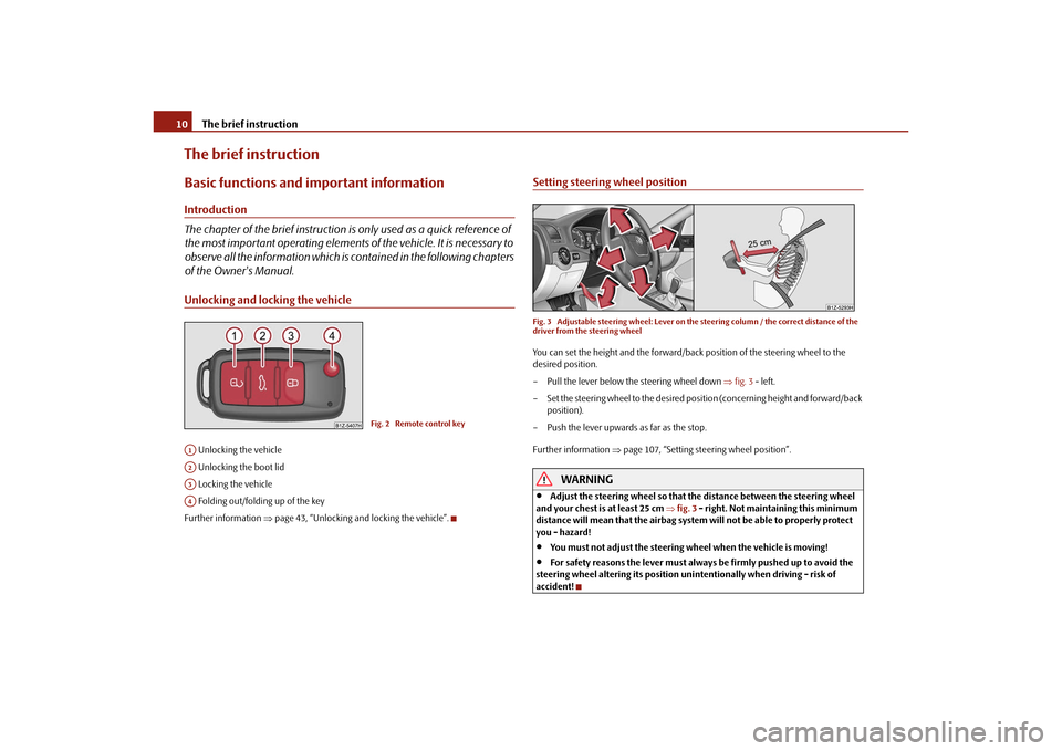
of the Owner's Manual.Unlocking and locking the vehicle Unlocking the vehicle
Unlocking the boot lid
Locking the vehicle
Folding out/folding up of the key
Further information page 43, “Unlocking and locking the vehicle”.
Setting steering wheel positionFig. 3 Adjustable steering wheel: Lever on the steering column / the correct distance of the
driver from the steering wheelYou can set the height and the forward/back position of the steering wheel to the
desired position.
– Pull the lever below the steering wheel down fig. 3 - left.
– Set the steering wheel to the desired posi tion (concerning height and forward/back
position).
– Push the lever upwards as far as the stop.
Further information page 107, “Setting steering wheel position”.
WARNING
Adjust the steering wheel so that the distance between the steering wheel
and your chest is at least 25 cm fig. 3 - right. Not maintaining this minimum
distance will mean that the airbag system will not be able to properly protect
you - hazard!
You must not adjust the steering wheel when the vehicle is moving!
For safety reasons the lever must always be firmly pushed up to avoid the
steering wheel altering its position uni ntentionally when driving - risk of
accident!
Fig. 2 Remote control key
A1A2A3A4s43s.1.book Page 10 Thursday, May 13, 2010 1:21 PM
Page 14 of 275
The brief instruction13
Using the system
Safety
Driving Tips
General Maintenance
Breakdown assistance
Technical Data
Slow wipe
Fast wipe
one time wipe
Automatic wipe/wash
Rear window wiper* Intermittent wipe - every 6 seconds
Automatic wipe/wash
Further information page 61, “Windshield wiper”.
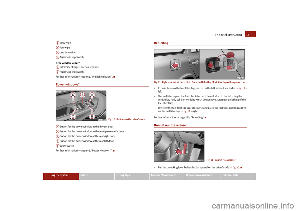
Power windows* Button for the power window in the driver's door
Button for the power window in the front passenger's door
Button for the power window at the rear right door
Button for the power window at the rear left door
Safety switch
Further information page 46, “Power windows*”.
RefuellingFig. 11 Right rear side of the ve hicle: Open fuel filler flap / fuel filler flap with cap unscrewed– In order to open the fuel filler flap, press it on the left side in the middle fig. 11 -
left.
– The fuel filler cap on the fuel filler tube must be unlocked to the left using the
vehicle key (only valid for vehicles which do not have automatic unlocking of the
fuel filler flap).
– Unscrew the fuel filler ca p anti-clockwise and place the fuel filler cap from above
on the fuel filler flap fig. 11 - right.
Further information page 195, “Refuelling”.Bonnet remote release– Pull the unlocking lever below the dash panel on the driver's side fig. 12 .
A2A3A4A5A6A7
Fig. 10 Buttons on the driver's door
AAABACADAS
Fig. 12 Bonnet release lever
s43s.1.book Page 13 Thursday, May 13, 2010 1:21 PM
Page 18 of 275
Instruments and warning lights17
Using the system
Safety
Driving Tips
General Maintenance
Breakdown assistance
Technical Data
Note
After filling up, it can occur that during dy namic driving (e.g. numerous curves, braking,
driving downhill and climbing a steep hill) the fuel gauge indicates approx. a fraction
less. When stopping or during less dynamic driving, the correct fuel supply quantity is
indicated. This effect is not a fault.Counter for distance drivenThe distance which you have driven with yo ur vehicle is shown in kilometres (km). In
some countries the measuring unit “mile” is used.
Reset button
If you hold the reset button page 15, fig. 15 pressed for about 1 second, the trip
counter is set back to zero.
Trip counter for distance driven
The trip counter indicates the distance which you have driven since it was last reset -
in steps of 100 metres or 1/10 of a mile.
Counter for distance driven
The counter for distance driven indicates th e total distance in kilometers or miles
which the vehicle has been driven.
Fa u l t d i s p l a y
If there is a fault in the instru ment cluster, the constant text Error appears in the display.
Have the fault rectified as soon as possible by a specialist workshop.
WARNING
Never seek to adjust the trip counter for distance driven while driving for safety
reasons!
Note
If vehicles which are fitted with the inform ation display* the display of the second
speed is activated in mph or km/h, this driving speed is indicated instead of the
counter for the total distance driven.
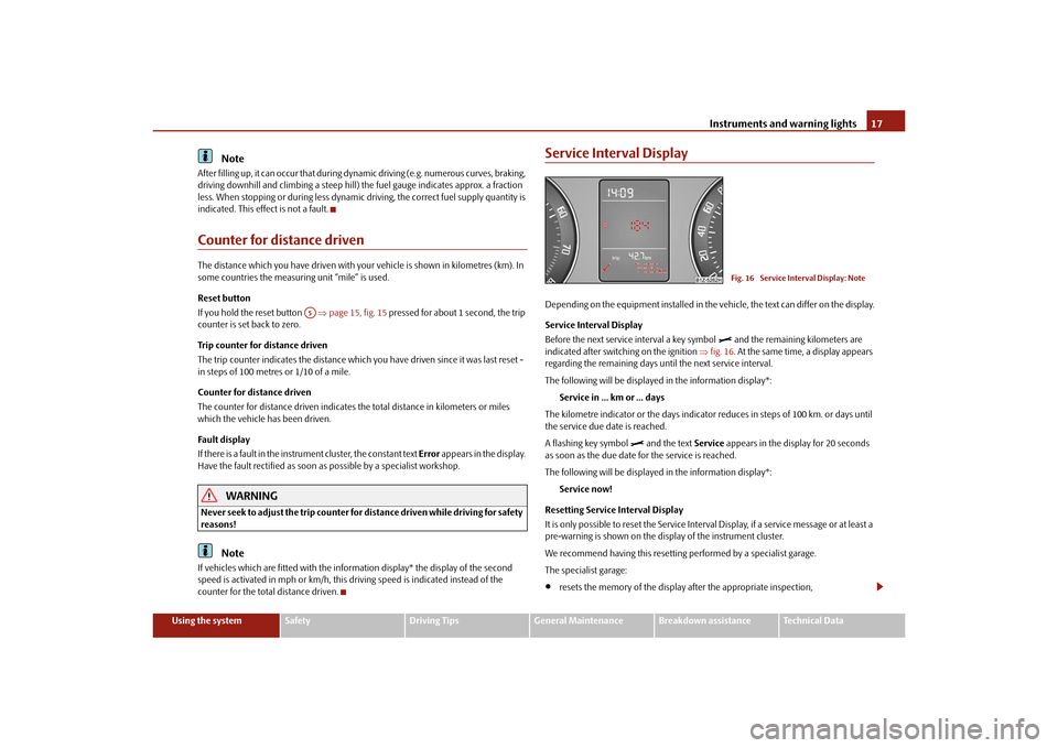
Service Interval DisplayDepending on the equipment installed in the vehicle, the text can differ on the display.
Service Interval Display
Before the next service interval a key symbol
and the remaining kilometers are
indicated after switching on the ignition fig. 16 . At the same time, a display appears
regarding the remaining days until the next service interval.
The following will be displayed in the information display*:
Service in ... km or ... days
The kilometre indicator or the days indicator reduces in steps of 100 km. or days until
the service due date is reached.
A flashing key symbol
and the text Service appears in the display for 20 seconds
as soon as the due date for the service is reached.
The following will be displayed in the information display*:
Service now!
Resetting Service Interval Display
It is only possible to reset the Service Interval Display, if a service message or at least a
pre-warning is shown on the disp lay of the instrument cluster.
We recommend having this resetting performed by a specialist garage.
The specialist garage:
resets the memory of the display after the appropriate inspection,
A5
Fig. 16 Service Interval Display: Note
s43s.1.book Page 17 Thursday, May 13, 2010 1:21 PM
Page 38 of 275
Unlocking and locking37
Using the system
Safety
Driving Tips
General Maintenance
Breakdown assistance
Technical Data
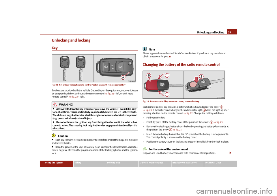
Unlocking and lockingKeyFig. 22 Set of keys without remote control / set of keys with remote control keyTwo keys are provided with the vehicle. Depending on the equipment, your vehicle can
be equipped with keys without radio remote control fig. 22 - left, or with radio
remote control* fig. 22 - right.
WARNING
Always withdraw the key whenever you leave the vehicle - even if it is only
for a short time. This is particularly important if children are left in the vehicle.
The children might otherwise start the en gine or operate electrical equipment
(e.g. power windows) - risk of injury!
Do not withdraw the ignition key from the ignition lock until the vehicle has
come to a stop. The steerin g lock might otherwise enga ge unintentionally - risk
of accident!Caution
Each key contains electronic components; therefore protect them against moisture
and severe shocks.
Keep the groove of the keys absolutely clean as impurities (textile fibres, dust etc.)
have a negative effect on the proper operation of the locking cylinder and the ignition
lock.
Note
Please approach an authorised Škoda Servic e Partner if you lose a key since he can
obtain a new one for you.Changing the battery of the radio remote controlFig. 23 Remote control key - remove cover / remove batteryEach remote control key contains a batt ery which is housed under the cover
fig. 23 . If the battery is discharged, the red in dicator light does not light up after
pressing a button on the remote control fig. 22 . Change the battery as follows:
– Fold open the key.
– Carefully press off the battery cover at the points of the arrows fig. 23 .
– Remove the discharged battery from the key by pressing the battery downwards at the point of the arrow fig. 23 .
– Insert the new battery. Ensure that the “+” symbol on the battery is facing upwards.
The correct polarity is shown on the battery cover.
– Position the battery cover on the key and press on it until it is heard to lock in place.
For the sake of the environment
Dispose of a used battery in accord ance with environmental regulations.
AB
AA
A1
A2
s43s.1.book Page 37 Thursday, May 13, 2010 1:21 PM
Page 39 of 275
Unlocking and locking
38Note
Pay attention to the correct pola rity when changing the battery.
The replacement battery must have the same specification as the original battery.
If it is still not be possible to unlock or lock the vehicle with the remote control even
after replacing the battery this means that the system has to be synchronised
page 44.
Electronic immobiliserThe electronic immobiliser prevents the vehicle being operated by an
unauthorised person.An electronic chip is integrated in the head of the key. The immobiliser is deactivated
with the aid of this chip when the key is in serted in the ignition lock. The electronic
immobiliser is automatically activated when you withdraw the ignition key from the
lock.
Note
It is only possible to start the engine of your car with a Genuine Škoda key with the
matching code.Child safety lockThe child safety lock prevents the re ar door from being opened from the
inside.
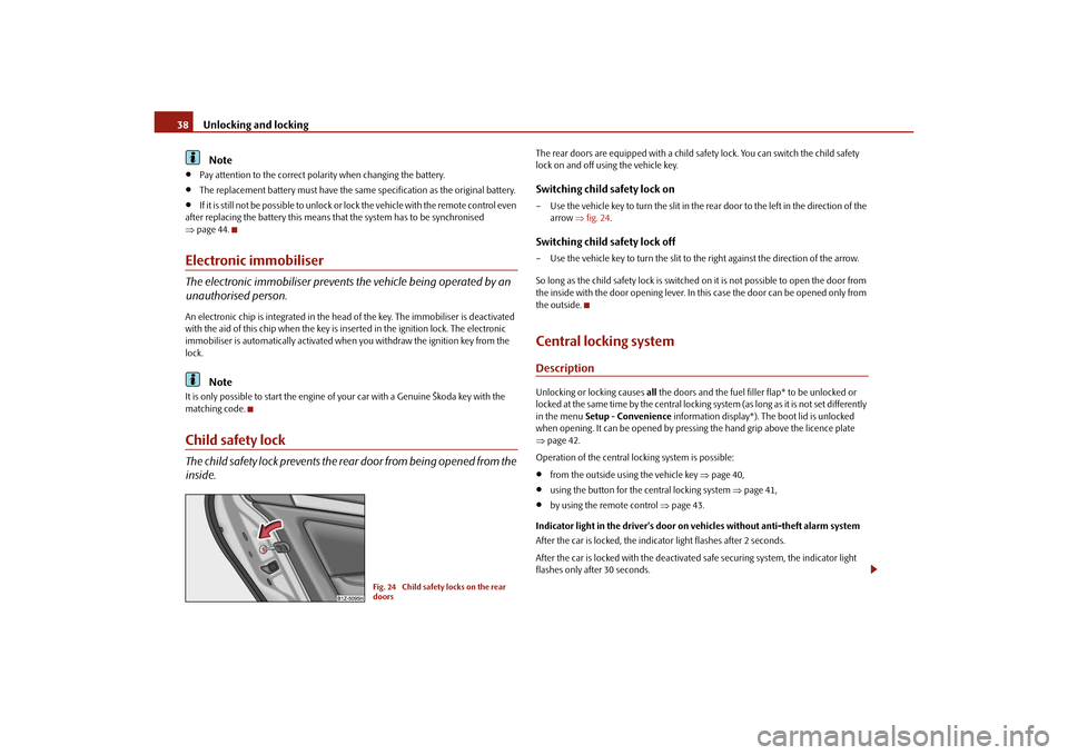
The rear doors are equipped with a child safe ty lock. You can switch the child safety
lock on and off using the vehicle key.Switching child safety lock on– Use the vehicle key to turn the slit in the rear door to the left in the direction of the arrow fig. 24 .Switching child safety lock off– Use the vehicle key to turn the slit to the right against the direction of the arrow.
So long as the child safety lock is switched on it is not possible to open the door from
the inside with the door opening lever. In this case the door can be opened only from
the outside.Central locking systemDescriptionUnlocking or locking causes all the doors and the fuel filler flap* to be unlocked or
locked at the same time by the central locking system (as long as it is not set differently
in the menu Setup - Convenience information display*). The boot lid is unlocked
when opening. It can be opened by pressi ng the hand grip above the licence plate
page 42.
Operation of the central locking system is possible:
from the outside using the vehicle key page 40,
using the button for the central locking system page 41,
by using the remote control page 43.
Indicator light in the driver's door on vehicles without anti-theft alarm system
After the car is locked, the indica tor light flashes after 2 seconds.
After the car is locked with the deactivate d safe securing system, the indicator light
flashes only after 30 seconds.
Fig. 24 Child safety locks on the rear
doors
s43s.1.book Page 38 Thursday, May 13, 2010 1:21 PM
Page 40 of 275
Unlocking and locking39
Using the system
Safety
Driving Tips
General Maintenance
Breakdown assistance
Technical Data
Indicator light in the driver's door on vehicles with anti-theft alarm system
After locking the vehicle the indicator light fl
ashes for 2 seconds fast, then more slowly.
If the vehicle is locked and the safe securing system page 39 is not operating, the
indicator light in the driver door flashes for about 2 seconds fast, goes out and starts to
flash slowly after about 30 seconds.
If the indicator light first of all flashes fast for about 2 seconds, afterwards lights up for
about 30 seconds and then flashes slowly, there is a fault in the system of the central
locking or the interior monitor* page 45. Visit a specialist garage to obtain assist-
ance.
Convenience operatio n of the windows
One can open and close the electrically powered windows when unlocking and
locking the vehicle page 48.
Opening a single door*
This function makes it possible to only unlock the driver's door. The other doors and
the fuel filler flap* remain locked and ar e only unlocked after repetitive unlocking.
If you wish, you can have your authorised Škoda Service Partner activate the function
of the single door opening mode.
On vehicles with information display*, this function can be switched on in the menu
Setup - Convenience - Door open.
Automatic locking and unlocking*
All the doors and the boot lid are locked au tomatically once the car reaches a speed of
about 15 km/h.
If the ignition key is withdrawn, the car is then automatically unlocked again. In addi-
tion, it is possible for the driver to unlock the car by pressing the central locking button
or by pulling the door opening lever.
If you wish, you can have a sp ecialist garage activate the automatic locking function.
WARNING
Locking the doors prevents involuntary opening in an exceptional situation (an
accident). Locked doors prevent unwanted entry into the vehicle from outside, for example at road crossings. Locked do
ors do, however, make it more difficult
for rescuers to get into the vehicle in an emergency - danger to life!
Note
In the event of an accident in which the airbags are deployed, the locked doors are
automatically unlocked in order to enable rescuers to gain access to the vehicle.
Only the front doors can be unlocked and locked using the key if the central locking
system fails. You can lock or unlock ma nually the other doors and the boot lid.
Emergency locking of the door page 41.
Emergency unlocking of the boot lid page 42.
Safe securingThe central locking system is equipped with a safe securing
7) system. Locking the
vehicle from the outside causes the door locks to be automatically blocked. It is not
possible to open the doors with the door ha ndle either from the inside or from the
outside. This acts as an effective deterrent for attemp ts to break into your vehicle.
You can deactivate the safe securing sy stem by locking twice within 2 seconds.
If the safe securing system is not operating, the warning light in the driver door flashes
for about 2 seconds fast, goes out and starts to flash slowly again after about
30°seconds.
The safe securing system is again activate d the next time the vehicle is unlocked and
locked again.
The doors can be opened from the inside if the vehicle is locked and the safe securing
system is deactivated:
The door is unlocked by actuating the door-opening lever.
The door opens upon actuating the door-opening lever again.
7)Only valid for some countries.WARNING (continued)
s43s.1.book Page 39 Thursday, May 13, 2010 1:21 PM
Page 41 of 275
Unlocking and locking
40WARNING
If the vehicle is locked from the outside and the safe securing system is acti-
vated, there must not be any person and animals in the vehicle as it is then not
possible to open either a door or a window from the inside. The locked doors
make it more difficult for rescuers to get into the vehicle in an emergency -
hazard!
Note
The anti-theft alarm system* is also activated with the deactivated safe securing
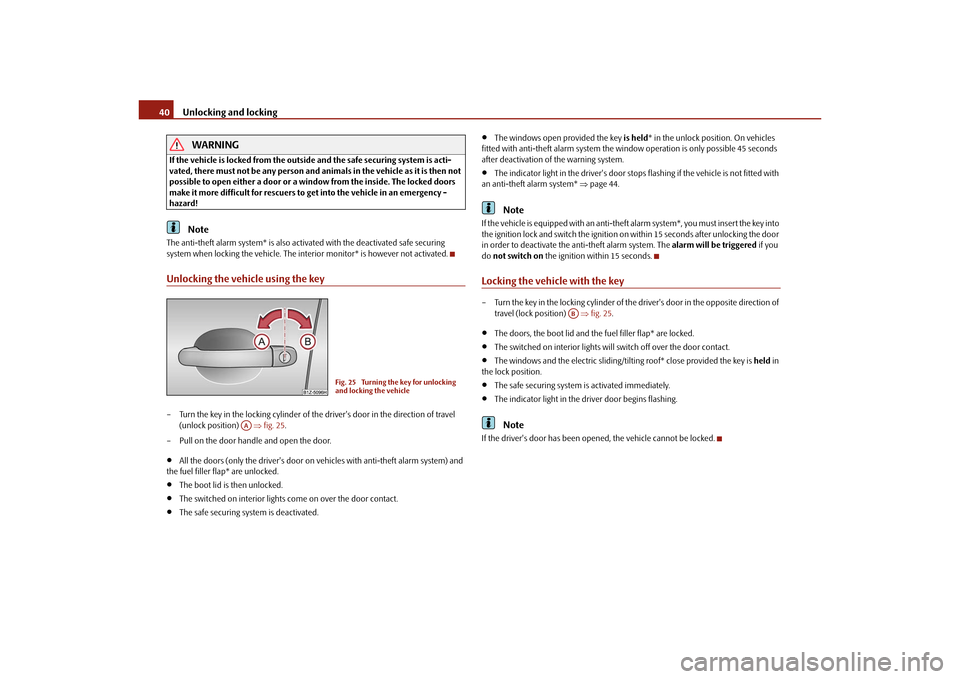
system when locking the vehicle. The interior monitor* is however not activated.Unlocking the vehicle using the key– Turn the key in the locking cylinder of the driver's door in the direction of travel
(unlock position) fig. 25 .
– Pull on the door handle and open the door.
All the doors (only the driver's door on vehicles with anti-theft alarm system) and
the fuel filler flap* are unlocked.
The boot lid is then unlocked.
The switched on interior lights come on over the door contact.
The safe securing system is deactivated.
The windows open provided the key is held * in the unlock position. On vehicles
fitted with anti-theft alarm system the window operation is only possible 45 seconds
after deactivation of the warning system.
The indicator light in the driver's door stops flashing if the vehicle is not fitted with
an anti-theft alarm system* page 44.Note
If the vehicle is equipped with an anti-theft alarm system*, you must insert the key into
the ignition lock and switch the ignition on within 15 seconds after unlocking the door
in order to deactivate the anti-theft alarm system. The alarm will be triggered if you
do not switch on the ignition within 15 seconds.Locking the vehicle with the key– Turn the key in the locking cylinder of the driver's door in the opposite direction of
travel (lock position) fig. 25 .
The doors, the boot lid and the fuel filler flap* are locked.
The switched on interior lights will switch off over the door contact.
The windows and the electric sliding/tilting roof* close provided the key is held in
the lock position.
The safe securing system is activated immediately.
The indicator light in the dr iver door begins flashing.Note
If the driver's door has been op ened, the vehicle cannot be locked.
Fig. 25 Turning the key for unlocking
and locking the vehicle
AA
AB
s43s.1.book Page 40 Thursday, May 13, 2010 1:21 PM
Page 42 of 275
Unlocking and locking41
Using the system
Safety
Driving Tips
General Maintenance
Breakdown assistance
Technical Data
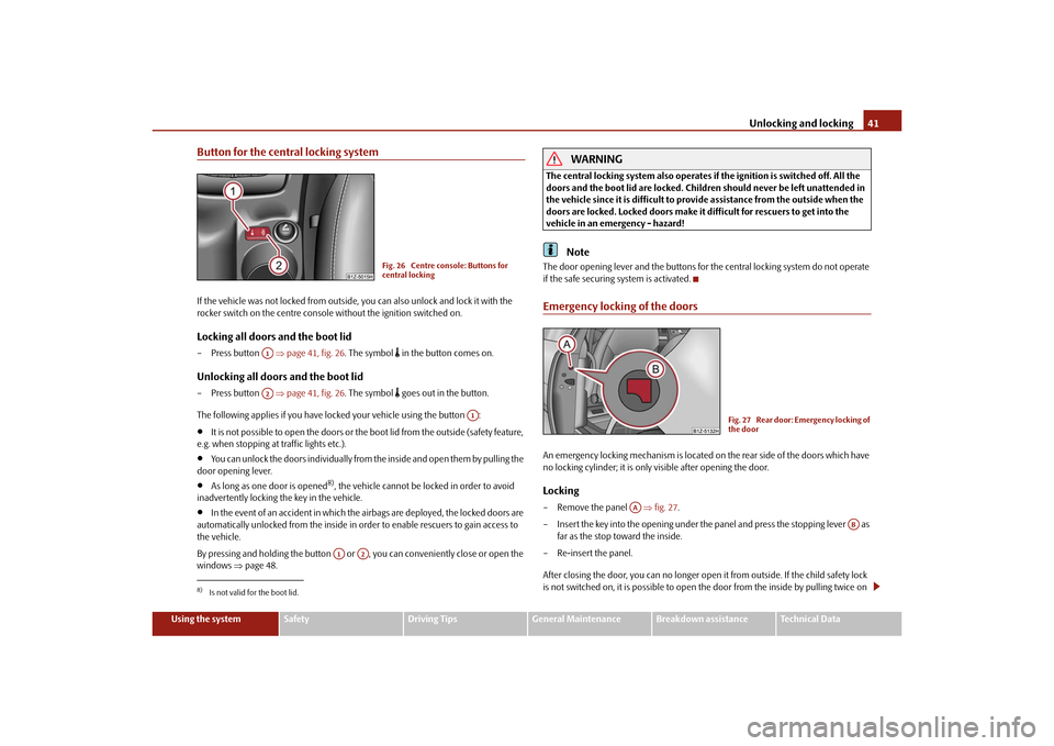
Button for the central locking systemIf the vehicle was not locked from outside, you can also unlock and lock it with the
rocker switch on the centre consol e without the ignition switched on.Locking all doors and the boot lid– Press button page 41, fig. 26. The symbol
in the button comes on.
Unlocking all doors and the boot lid– Press button page 41, fig. 26. The symbol
goes out in the button.
The following applies if you have locked your vehicle using the button :
It is not possible to open the doors or the boot lid from the outside (safety feature,
e.g. when stopping at traffic lights etc.).
You can unlock the doors individually from the inside and open them by pulling the
door opening lever.
As long as one door is opened
8), the vehicle cannot be locked in order to avoid
inadvertently locking the key in the vehicle.
In the event of an accident in which the airbags are deployed, the locked doors are
automatically unlocked from the inside in orde r to enable rescuers to gain access to
the vehicle.
By pressing and holding the button or , you can conveniently close or open the
windows page 48.
WARNING
The central locking system al so operates if the ignition is switched off. All the
doors and the boot lid are locked. Children should never be left unattended in
the vehicle since it is difficult to prov ide assistance from the outside when the
doors are locked. Locked doors make it difficult for rescuers to get into the
vehicle in an emergency - hazard!
Note
The door opening lever and the buttons for the central locking system do not operate
if the safe securing system is activated.Emergency locking of the doorsAn emergency locking mechanism is located on the rear side of the doors which have
no locking cylinder; it is only visible after opening the door.Locking– Remove the panel fig. 27 .
– Insert the key into the opening under the panel and press the stopping lever as far as the stop toward the inside.
– Re-insert the panel.
After closing the door, you can no longer open it from outside. If the child safety lock
is not switched on, it is possible to open the door from the inside by pulling twice on
8)Is not valid for the boot lid.
Fig. 26 Centre console: Buttons for
central locking
A1A2
A1
A1
A2
Fig. 27 Rear door: Emergency locking of
the door
AA
AB
s43s.1.book Page 41 Thursday, May 13, 2010 1:21 PM
Page 43 of 275
Unlocking and locking
42
the door opening lever. If the child safety lock is switched on, it is necesary to also open
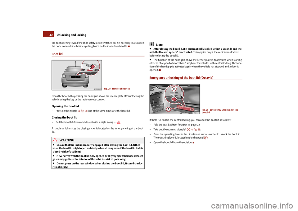
the door from outside besides pulling twice on the inner door handle.Boot lidOpen the boot lid by pressing the hand grip above the licence plate after unlocking the
vehicle using the key or the radio remote control.Opening the boot lid–Press on the handle fig. 28 and at the same time raise the boot lid.Closing the boot lid– Pull the boot lid down and cl ose it with a slight swing .
A handle which makes the closing easier is located on the inner paneling of the boot
lid.
WARNING
Ensure that the lock is properly enga ged after closing the boot lid. Other-
wise, the boot lid might open suddenly when driving even if the boot lid lock is
closed - risk of accident!
Never drive with the boot lid fully open ed or slightly ajar otherwise exhaust
gases may get into the interior of the vehicle - risk of poisoning!
Do not press on the rear window when closing the boot lid, it could crack -
risk of injury!
Note
After closing the boot lid, it is automatically locked within 2 seconds and the
anti-theft alarm system* is activated. This applies only if the vehicle was locked
before closing the boot lid.
The function of the hand grip above the li cence plate is deactivated when starting
off or as of a speed of more than 5 km/hour for vehicles with central locking. The func-
tion of the hand grip is activated again when the vehicle has stopped and a door is
opened.
Emergency unlocking of the boot lid (Octavia)If there is a fault in the central locking, you can open the boot lid as follows:
– Fold the seat backrest forwards page 72.
– Take out the warning triangle* fig. 29 .
– Press the operating lever in the direction of arrow in order to unlock the boot lid.
The operating lever is located under the panel .
– Open the boot lid from the outside.
Fig. 28 Handle of boot lid
Fig. 29 Emergency unlocking of the
boot lid
AA
AB
s43s.1.book Page 42 Thursday, May 13, 2010 1:21 PM