sensor SKODA OCTAVIA 2010 2.G / (1Z) User Guide
[x] Cancel search | Manufacturer: SKODA, Model Year: 2010, Model line: OCTAVIA, Model: SKODA OCTAVIA 2010 2.G / (1Z)Pages: 275, PDF Size: 16.43 MB
Page 67 of 275
Lights and Visibility
66Note
If the exterior mirrors are folded in using the remote control* of the vehicle key,
these are folded back into the driving positi on after opening the door or switching on
the ignition.
If the exterior mirrors are folded in using the rotary knob page 65, fig. 54 , they
can only be folded back into the dr iving position using the rotary knob.
If the exterior mirrors were folded in us ing the remote control* of the vehicle key
and if the rotary knob was in the fold-in po sition before switching on the ignition, the
mirrors remain in the fold-in position the next time the ignition is switched on. Folding
back into the driving position is performed by actuating the rotary knob in a different
position from the fold-in position.
Do not touch the surfaces of the exterior mirrors if the exterior mirror heater is
switched on.
You can set the exterior mirrors by hand, if the power setting function fails at any
time by pressing on the edge of the mirror surface.
Contact your specialist garage if a fault ex ists with the power setting of the exterior
mirrors.
Automatic dimming exterior mirror on the driver's side*The exterior mirror on the driver's side is dimmed together with the interior mirror. If
the automatic dimming is switched on, the mirror dims automatically depending on
the light striking the mirror from the rear.
After the reverse gear is engaged, the mirror always moves back into the normal (not
dimmed) position.
Note
Automatic mirror dimming operates only properly if the sun screen* for the rear
window is not in use or the light striking the rear of the interior rear-view mirror is not
affected by other objects.
Do not affix any stickers in front of the light sensor, so that you do not impair the
automatic dimming function or put it out of operation.
If you switch off the automatic dimming interior rear-view mirror, also the exterior
mirror dimming is switched off.
s43s.1.book Page 66 Thursday, May 13, 2010 1:21 PM
Page 103 of 275
Heating and air conditioning system
102
Overview of the control elements
The controls enable a separate setting of the temperature for the left
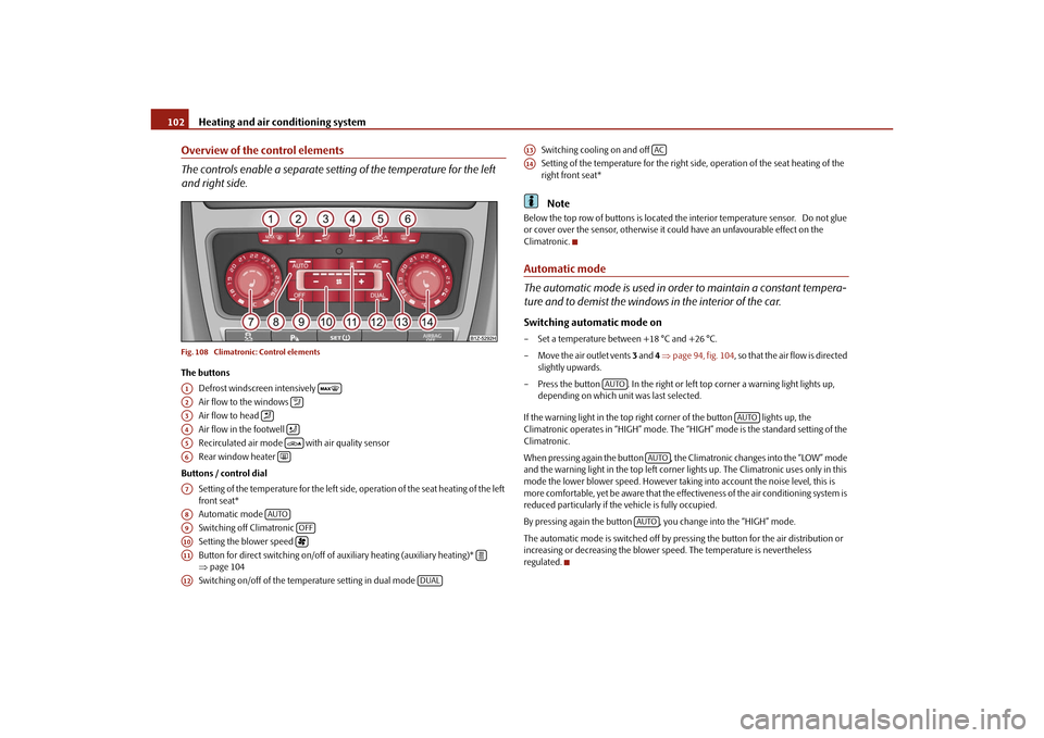
and right side.Fig. 108 Climatronic: Control elementsThe buttons
Defrost windscreen intensively
Air flow to the windows
Air flow to head
Air flow in the footwell
Recirculated air mode with air quality sensor
Rear window heater
Buttons / control dial Setting of the temperature for the left side, operation of the seat heating of the left
front seat*
Automatic mode
Switching off Climatronic
Setting the blower speed
Button for direct switching on/off of auxiliary heating (auxiliary heating)*
page 104
Switching on/off of the temperature setting in dual mode Switching cooling on and off
Setting of the temperature for the right side, operation of the seat heating of the
right front seat*
Note
Below the top row of buttons is located the interior temperature sensor. Do not glue
or cover over the sensor, otherwise it co
uld have an unfavourable effect on the
Climatronic.Automatic mode
The automatic mode is used in orde r to maintain a constant tempera-
ture and to demist the windows in the interior of the car.Switching automatic mode on– Set a temperature between +18 °C and +26 °C.
– Move the air outlet vents 3 and 4 page 94, fig. 104, so that the air flow is directed
slightly upwards.
– Press the button . In the right or left top corner a warning light lights up, depending on which unit was last selected.
If the warning light in the top right corner of the button lights up, the
Climatronic operates in “HIGH” mode. The “HIGH” mode is the standard setting of the
Climatronic.
When pressing again the button , the Cl imatronic changes into the “LOW” mode
and the warning light in the top left corner li ghts up. The Climatronic uses only in this
mode the lower blower speed. However taking into account the noise level, this is
more comfortable, yet be aware that the effectiveness of the air conditioning system is
reduced particularly if th e vehicle is fully occupied.
By pressing again the button , you change into the “HIGH” mode.
The automatic mode is switched off by pressing the button for the air distribution or
increasing or decreasing the blower speed. The temperature is nevertheless
regulated.
A1
A2
A3
A4
A5
A6
A7A8
AUTO
A9
OFF
A10
A11
A12
DUAL
A13
AC
A14
AUTO
AUTO
AUTOAUTO
s43s.1.book Page 102 Thursday, May 13, 2010 1:21 PM
Page 104 of 275
Heating and air conditioning system103
Using the system
Safety
Driving Tips
General Maintenance
Breakdown assistance
Technical Data
switching cooling on and offswitching cooling on and off–Press the button page 102, fig. 108 . The warning light lights up in the button.
– When you again press the switch , the cooling system is switched off. The warning light in the button goes out. Only the function of the ventilation remains
active when no lower temperature than the outside temperature can be reached.Setting temperatureYou can separate the interior temperature for the left and right side separately.
– You can set the temperature for both sides after switching on the ignition with the
control dial .
– If you wish to set the temperature for the right side, turn the control dial . The warning light in the button lights up, this indicates that differing tempera-
tures for the left and right side can be set.
If the warning light in the button lights up, the temperature for both sides
cannot be set with the control dial . You can reinitiate this function by pressing the
button . The warning light in the button which indicates the possibility to set
differing temperatures for the left and right side, goes out.
You can set the interior temperature between +18°C and +26°C. The interior temper-
ature is regulated automatically within this range. If you chose a temperature lower
than +18°C, a blue symbol lights up at the start of the numerical scale. If you chose a
temperature higher than +26°C, a red symbol lights up at the end of the numerical
scale. In both limit positions the Climatroni c operates at maximum cooling or heating
capacity, respectively. The temperatur e is not controlled in this case.
Lengthy and uneven distribution of the air flow out of the vents (in particul ar at the leg
area) and large differences in temperature, for example when getting out of the vehicle,
can result in chills in sensitive persons.
Recirculated air mode
In recirculated air mode air is sucked out of the interior of the vehicle
and then fed back into the interior. When the automatic air distribution
control is switched on, an air quality sensor measures the concentration
of pollutants in the drawn-in air.Recirculated air mode prevents polluted air outside the vehicle from getting into the
vehicle, for example when driving through a t unnel or when standing in a traffic jam. If
a considerable increase in concentration of pollutants is recognized by the air quality
sensor, when the automatic air distribution co ntrol is switched on, the air distribution
control will temporarily be switched off. If the concentration of pollutants decreases to
the normal level, the air distribution control is automatically switched off so that fresh
air can be guided into the vehicle interior.Switching recirculated air mode on– Press the button repeatedly until the warning light on the left side of the
button lights up.Switch on automatic air distribution control– Press the button repeatedly until the warning light on the right side of the
button lights up.Switch off automatic air distribution control temporarily– If the air quality sensor does not switch on the air distribution control automatically when there is a nauseating smell, you can switch it on yourself by pressing the
button *. The warning light lights up in the button on the left side.Switching recirculated air mode off– Press the button or press the bu tton repetitively, until the warning
lights in the button go out.
WARNING
You should not leave recirculated air mode on over a longer period of time, as
“stale” air may result in fatigue in the driver and occupants, divert your atten-
AC
AC
A7
A14
DUALDUALA7
DUAL
AUTO
s43s.1.book Page 103 Thursday, May 13, 2010 1:21 PM
Page 112 of 275
Starting-off and Driving111
Using the system
Safety
Driving Tips
General Maintenance
Breakdown assistance
Technical Data
Releasing the handbrake– Pull the handbrake lever up slightly and at the same time press in the locking
button fig. 113 .
– Hold the button pressed and push the handbrake lever down fully .
The handbrake warning light
lights up when the handbrak e is applied, provided the
ignition is on.
A warning signal sounds and the following text appears in the display* if you have inad-
vertently driven off with the handbrake applied:
Release parking brake!
The handbrake warning is acti vated if you drive at a speed of more than 6 km/h for
more than 3 seconds.
WARNING
Please note that the handbrake must be fully released. A handbrake which
is only partially released can result in the rear brakes overheating which will
have a negative effect on the operation of the brake system - risk of accident! In
addition this can result in premature wear of the rear brake pads.
Never leave children unattended in the vehicle. The children might, for
example, release the handbrake or take the vehicle out of gear. The vehicle
might then move off - risk of accident!Caution
After the car has come to a stop, always firs t of all apply the handbrake firmly before
then additionally engaging a gear (manual gearbox) or moving the selector lever into
position P (automatic gearbox).
Rear parking aid*The parking aid provides a warning of obstacles behind the vehicle.The audible parking aid determines the di stance between the rear bumper and an
obstacle located behind the ve hicle with the aid of ultrasound sensors. The tones of
the parking aid can be adapted in th e menu of the information display* page 25.
The sensors are integrated in the rear bumper.
Range of sensors
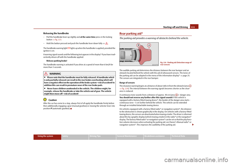
The clearance warning begins at a distance of about 160 cm from the obstacle (area
fig. 114 ). The interval between the warning signals becomes shorter as the clear-
ance is reduced.
A continuous tone sounds from a distance of approx. 30 cm (area ) - danger area.
You should not reverse any further after this signal sounds! If the vehicle is
equipped with a factory-fitted towing device*, the border of the danger area starts -
continuous tone - 5 cm further behind th e vehicle. The vehicle can be extended
through an installed deta chable towing device.
On vehicles equipped with a factory-fitted radio* or navigation system*, the distance
to the obstruction is shown graphically in the display. On vehicles with a factory-fitted
towing device, the sensors are deactivated when towing a trailer. The driver is informed
about this by a graphic display (vehicle towing a trailer) in the radio* or the navigation*
display. The factory-fitted radio* or navigati on system* can be set so that the play func-
tion volume decreases when activating the parking aid, see Owner's Manual radio* or
navigation system*. This improves the audibility of the parking aid.
Fig. 114 Parking aid: Detection range of
rear sensors
AA
AB
s43s.1.book Page 111 Thursday, May 13, 2010 1:21 PM
Page 113 of 275
Starting-off and Driving
112
Activating
The parking aid is activated automatically when reverse gear is engaged and the igni-
tion is turned on. This is confirme d by a brief acknowledgement signal.
Deactivating
The parking aid is deactivated by removing the reverse gear.
WARNING
The parking aid is not a substitute for the driver paying proper attention and
it is always the driver's responsibility to take care when parking the vehicle or
carrying out similar manoeuvres.
You should therefore satisfy yourself, befo re reversing, that there is no small
obstacle, such as a rock, thin post, trailer drawbar etc., behind your vehicle.
Such an obstacle might not be within the range detected by the sensors.
Under certain circumstances, surfaces of certain objects and types of
clothing cannot reflect the signal of the parking aid. Thus, these objects or
people who wear such clothing are not recognised by the sensors of the parking
aid.Note
The parking aid does not operate if you are towing a trailer (applies to models
which feature a factory-fitted towing device*).
If a warning signal sounds for about 3 seconds after switching the ignition on and
engaging reverse gear, and there is no obstac le close to your vehicle, this indicates a
system fault. Have the fault rectified by a specialist workshop.
The sensors must be kept clean and free of ice to enable the parking aid to operate
properly.
Front and rear parking aid*The parking aid provides a warning of obstacles in front and behind the
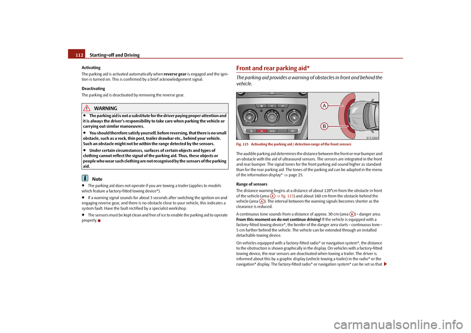
vehicle.Fig. 115 Activating the parking aid / detection range of the front sensorsThe audible parking aid determines the distan ce between the front or rear bumper and
an obstacle with the aid of ultrasound sensors. The sensors are integrated in the front
and rear bumper. The signal tones for the fr ont parking aid sound higher as standard
than for the rear parking aid. The tones of the parking aid can be adapted in the menu
of the information display* page 25.
Range of sensors
The distance warning begins at a distance of about 120°cm from the obstacle in front
of the vehicle (area fig. 115 ) and about 160 cm from the obstacle behind the
vehicle (area ). The interval between th e warning signals becomes shorter as the
clearance is reduced.
A continuous tone sounds from a distance of approx. 30 cm (area ) - danger area.
From this moment on do not continue driving! If the vehicle is equipped with a
factory-fitted towing device*, the border of the danger area starts - continuous tone -
5 cm further behind the vehicle. The vehi cle can be extended through an installed
detachable towing device.
On vehicles equipped with a factory-fitted radio* or navigation system*, the distance
to the obstruction is shown graphically in the display. On vehicles with a factory-fitted
towing device, the rear sensors are deactivated when towing a trailer. The driver is
informed about this by a graphic display (vehic le towing a trailer) in the radio* or the
navigation* display. The factory-fitted radio* or navigation system* can be set so that
AA
AA
AB
s43s.1.book Page 112 Thursday, May 13, 2010 1:21 PM
Page 114 of 275
Starting-off and Driving113
Using the system
Safety
Driving Tips
General Maintenance
Breakdown assistance
Technical Data
the play function volume decreases when activating the parking aid, see Owner's
Manual radio* or navigation system*. This
improves the audibility of the parking aid.
Activating
The parking aid is activated when the reverse gear is engaged and the ignition is
switched on or by pressing the button page 112, fig. 115 - left, the symbol lights
up in the button. The activation is conf irmed by a brief acknowledgement signal.
Deactivating
The parking aid is deactivated after pressing the button page 112, fig. 115 - left,
or at a speed of more than 10 km/h - the symbol
in the button is no longer illumi-
nated.
WARNING
The parking aid is not a substitute for the driver paying proper attention and
it is always the driver's responsibility to take care when reversing the vehicle or
carrying out similar manoeuvres.
You should therefore satisfy yourself, befo re reversing, that there is no small
obstacle, such as a rock, thin post, trailer drawbar etc., in front or behind your
vehicle. Such an obstacle might not be within the range detected by the sensors.
Under certain circumstances, surfaces of certain objects and types of
clothing cannot reflect the signal of the parking aid. Thus, these objects or
people who wear such clothing are not recognised by the sensors of the parking
aid.Note
Only the front parking aid operates if yo u are towing a trailer (applies only to
models which feature a factory-fitted towing device*).
If a warning signal sounds for about 3 seco nds after activating the system and there
is no obstacle close to your vehicle, this indicates a system fault. The fault is confirmed
additionally when the symbol flashes in the button page 112, fig. 115 - left.
Have the fault rectified by a specialist workshop.
The sensors must be kept clean and free of ice to enable the parking aid to operate
properly.
If the parking aid is activated and the sele ctor lever of the automatic gearbox is in
the position , warning signal indicates inte rruption (vehicle can no longer move).
Cruise control system (CCS)*IntroductionThe cruise control system (CCS) maintains a constant speed, more than 30 km/h (20
mph), once it has been set, without you havi ng to depress the accelerator pedal. This
is only possible within the range which is permitted by the power output and braking
power of the engine. The cruise control system makes it possible - particularly on long
journeys - for you to rest your “accelerator foot”.
WARNING
For safety reasons, the cruise control system must not be used in dense
traffic or on unfavourable ro ad surfaces (such as icy roads, slippery roads, loose
gravel) - risk of accident!
In order to prevent unintentional use of the cruise control system, always
switch off the system after use.Note
Models fitted with a manual gearbox: Alwa ys depress the clutch pedal if you switch
on the cruise control system when the gearbo x is in Neutral! Otherwise the engine can
rev up unintentionally.
The cruise control system is not able to maintain a constant speed when driving on
steep downhill sections. The weight of the vehicle increases the speed at which it
travels. One should shift down in good time to a lower gear or slow the vehicle down
by applying the foot brake.
It is not possible on vehicles fitted with an automatic gearbox to switch on the
cruise control system if the sele ctor lever is in the position P, N or R.
AP
s43s.1.book Page 113 Thursday, May 13, 2010 1:21 PM
Page 155 of 275
Airbag system
154
Function of the side airbags
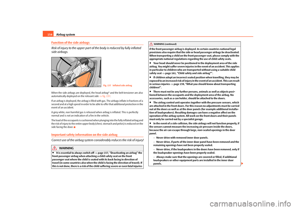
Risk of injury to the upper part of the body is reduced by fully inflated
side airbags.When the side airbags are deployed, the head airbag* and the belt tensioner are also
automatically deployed on the relevant side fig. 137 .
If an airbag is deployed, the airbag is filled with gas. The airbags inflate in fractions of a
second and at a high speed in order to be able to offer that additional protection in the
event of an accident.
A grey white, non harmful gas is released when airbag is inflated. This is perfectly
normal and is not an indicati on of a fire in the vehicle.
The load of the occupants is cushioned when plunging into the fully inflated airbag and
the risk of injury to the entire upper body (chest, stomach and pelvis) is reduced on the
side facing the door.Important safety information on the side airbag
Correct use of the airbag system cons iderably reduces the risk of injury!
WARNING
It is essential to always switch off page 157, “Deactivating an airbag” the
front passenger airbag when attachin g a child safety seat on the front
passenger seat where the child is seated with its back facing in direction of
travel (in some countries also when the child is facing the direction of travel). If
this is not done, there is a risk of the ch ild suffering severe or even fatal injuries if the front passenger airbag is deploy
ed. In certain countries national legal
provisions also require that the side or head passenger airbags be deactivated.
When transporting a child on the front passenger seat, please comply with the
appropriate national regulations regarding the use of child safety seats.
Your head should never be positioned in the deployment area of the side
airbag. You might suffer severe injuries in the event of an accident. This applies
in particular to children who are transported without using a suitable child
safety seat page 161, “Child safety and side airbag*”.
If children adopt an incorrect seated position when travelling, they may be
exposed to an increased risk of injury in the event of an accident. This can result
in serious injuries page 159, “What you should know about transporting
children!”.
There must not be any further persons, animals as well as objects posi-
tioned between the occupants and the deployment area of the airbag. No
accessories, such as a can holder, should be attached to the doors.
The airbag control unit operates togeth er with the pressure sensors, which
are attached in the front doors. For this reason no adjustments must be carried
out at the doors as well as at the door panels (for example additional installa-
tion of loudspeakers). Resulting damage s can have a negative affect on the
operation of the airbag system. All work on the front doors and their panels
must only be carried out by a specialist garage.
In the event of a side collision, the side airbags will not function properly, if
the sensors cannot measure the increasi ng air pressure inside the doors,
because the air can escape through lar ge, non-sealed openings in the door
panel.
Never drive with removed inner door panels.
Never drive, if parts of the inner do or panel have been removed and the
remaining openings have not been properly sealed.
Never drive, if the loudspeakers in the doors have been removed, only if
the loudspeaker openings have been properly sealed.
Always make sure that the openings are covered or filled, if additional
loudspeakers or other equipment part s are installed in the inner door
panels.
Fig. 137 Inflated side airbag
WARNING (continued)
s43s.1.book Page 154 Thursday, May 13, 2010 1:21 PM
Page 157 of 275
Airbag system
156
Function of the head airbags
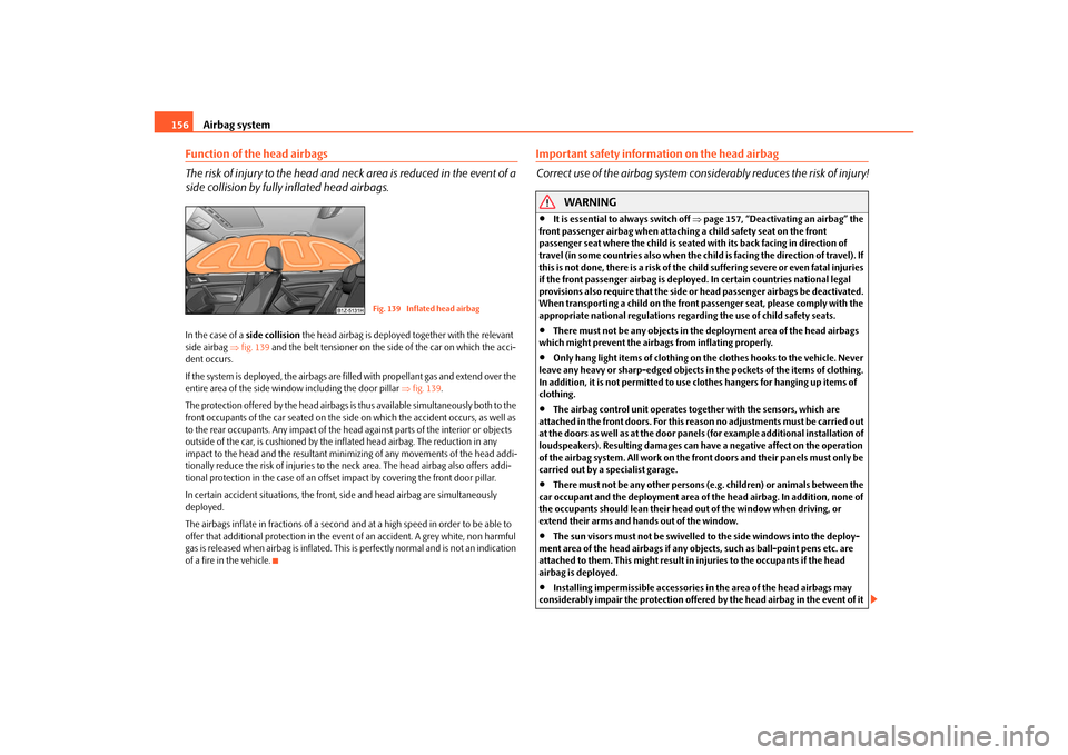
The risk of injury to the head and neck area is reduced in the event of a
side collision by fully inflated head airbags.In the case of a side collision the head airbag is deployed together with the relevant
side airbag fig. 139 and the belt tensioner on the side of the car on which the acci-
dent occurs.
If the system is deployed, the airbags are filled with propellant gas and extend over the
entire area of the side wind ow including the door pillar fig. 139 .
The protection offered by the head airbags is thus available simultaneously both to the
front occupants of the car seated on the side on which the accident occurs, as well as
to the rear occupants. Any impact of the head against parts of the interior or objects
outside of the car, is cushioned by the in flated head airbag. The reduction in any
impact to the head and the resultant minimi zing of any movements of the head addi-
tionally reduce the risk of injuries to the neck area. The head airbag also offers addi-
tional protection in the case of an offset impact by covering the front door pillar.
In certain accident situations, the front, side and head airbag are simultaneously
deployed.
The airbags inflate in fractions of a second an d at a high speed in order to be able to
offer that additional protection in the even t of an accident. A grey white, non harmful
gas is released when airbag is inflated. This is perfectly normal and is not an indication
of a fire in the vehicle.
Important safety information on the head airbag
Correct use of the airbag system cons iderably reduces the risk of injury!
WARNING
It is essential to always switch off page 157, “Deactivating an airbag” the
front passenger airbag when attaching a child safety seat on the front
passenger seat where the child is seated with its back facing in direction of
travel (in some countries also when the chil d is facing the direction of travel). If
this is not done, there is a risk of the ch ild suffering severe or even fatal injuries
if the front passenger airbag is deploy ed. In certain countries national legal
provisions also require that the side or head passenger airbags be deactivated.
When transporting a child on the front passenger seat, please comply with the
appropriate national regulations regarding the use of child safety seats.
There must not be any objects in the deployment area of the head airbags
which might prevent the airbags from inflating properly.
Only hang light items of clothing on the clothes hooks to the vehicle. Never
leave any heavy or sharp-edged objects in the pockets of the items of clothing.
In addition, it is not permitted to use clothes hangers for hanging up items of
clothing.
The airbag control unit operates to gether with the sensors, which are
attached in the front doors. For this reason no adjustments must be carried out
at the doors as well as at the door panels (for example additional installation of
loudspeakers). Resulting damages can have a negative affect on the operation
of the airbag system. All work on the front doors and their panels must only be
carried out by a specialist garage.
There must not be any other persons (e.g. children) or animals between the
car occupant and the deployment area of the head airbag. In addition, none of
the occupants should lean their head out of the window when driving, or
extend their arms and hands out of the window.
The sun visors must not be swivelled to the side windows into the deploy-
ment area of the head airbags if any objects, such as ball-point pens etc. are
attached to them. This might result in injuries to the occupants if the head
airbag is deployed.
Installing impermissible accessories in the area of the head airbags may
considerably impair the protection offered by the head airbag in the event of it
Fig. 139 Inflated head airbag
s43s.1.book Page 156 Thursday, May 13, 2010 1:21 PM
Page 168 of 275
Intelligent Technology167
Using the system
Safety
Driving Tips
General Maintenance
Breakdown assistance
Technical Data
Driving TipsIntelligent TechnologyElectronic stability programme (ESP)*GeneralThe ESP aids you in maintaining control of your vehicle in situations in which the
vehicle is driving at its dynamic limits, such as entering a curve fast. The risk of skidding
is reduced and your vehicle thus offers greater driving stability depending on the
conditions of the road surface. The system operates at all speeds.
The following systems are integrated into the electronic stability programme:
Electronic Differential Lock (EDL),
Traction control system (TCS),
active driver-steering recommendation (DSR),
Antilock brake system (ABS),
Brake Assist,
Uphill Start Assist
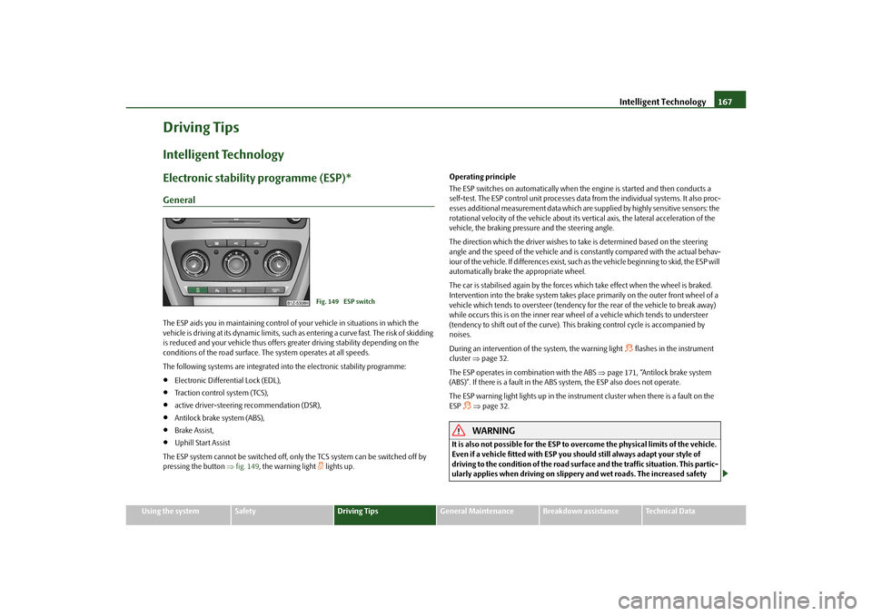
The ESP system cannot be switched off, only the TCS system can be switched off by
pressing the button fig. 149 , the warning light
lights up. Operating principle
The ESP switches on automatically when the engine is started and then conducts a
self-test. The ESP control unit processes data from the individual systems. It also proc-
esses additional measurement data which are supplied by highly sensitive sensors: the
rotational velocity of the vehicle about its ve
rtical axis, the lateral acceleration of the
vehicle, the braking pressure and the steering angle.
The direction which the driver wishes to take is determined based on the steering
angle and the speed of the vehicle and is co nstantly compared with the actual behav-
iour of the vehicle. If differences exist, such as the vehi cle beginning to skid, the ESP will
automatically brake the appropriate wheel.
The car is stabilised again by the forces wh ich take effect when the wheel is braked.
Intervention into the brake system takes place primarily on the outer front wheel of a
vehicle which tends to oversteer (tendency for the rear of the vehicle to break away)
while occurs this is on the inner rear wh eel of a vehicle which tends to understeer
(tendency to shift out of the curve). This braking control cycle is accompanied by
noises.
During an intervention of the system, the warning light
flashes in the instrument
cluster page 32.
The ESP operates in combination with the ABS page 171, “Antilock brake system
(ABS)”. If there is a fault in the ABS system, the ESP also does not operate.
The ESP warning light lights up in the instrument cluster when there is a fault on the
ESP
page 32.WARNING
It is also not possible for the ESP to overcome the physical limits of the vehicle.
Even if a vehicle fitted with ESP you should still always adapt your style of
driving to the condition of the road surfac e and the traffic situation. This partic-
ularly applies when driving on slippery and wet roads. The increased safety
Fig. 149 ESP switch
s43s.1.book Page 167 Thursday, May 13, 2010 1:21 PM
Page 169 of 275
Intelligent Technology
168
offered must not tempt you to take greater risks than otherwise - risk of an acci-
dent!
Note
All four wheels must be fitted with the same tyres in order to achieve problem-free
operation of the ESP. Differing rolling circum ferences of the tyres can lead to an unde-
sirable reduction in the engine output.
Changes to vehicle (e.g. on engine, on th e brakes, on chassis or another combina-
tion of tyres and wheels) can influence the function of the ESP page 214, “Accesso-
ries, changes and replacement of parts”.
Electronic Differential Lock (EDL and XDL)*
The electronic differential lock prev ents an individual wheel from slip-
ping.Models fitted with ESP ar e equipped with electronic differential lock (EDL).
General
The EDL makes it much easier, and sometimes at all possible, to start off, accelerate
and climb a steep hill when the conditions of the road surface are unfavourable.
Operating principle
The EDL is activated automaticall y, that is without any action on the part of the driver.
It monitors the speeds of the driven wheels with the aid of the ABS sensors. Should
only one drive wheel begin spinning on a slippery surface there will be an appreciable
difference in the speed of the driven wheels. The EDL function brakes the slipping
wheel and the differential transmits a greate r driving force to the other driven wheel.
This control process is also accompanied by noises.
Overheating of the brakes
The EDL switches off automatica lly if unusually severe stresses exist in order to avoid
excessive heat generation in the disc brake on the wheel which is being braked. The
vehicle can continue to be driven and has the same characteristics as a vehicle not
fitted with EDL. The EDL switches on again automatically
as soon as the brake has cooled down.
XDL function (only for Octavia RS)
The XDL function is an extension to the electronic differential lock. The XDL function
does not respond to traction, but to the relief of the inner front wheel during fast
cornering. An active brake intervention on the brake of the inner wheel prevents it from
spinning. Thus, the trac tion is improved and the vehicle continues to follow the desired
track.
WARNING
Carefully depress the accelerator when accelerating on uniformly slippery
road surfaces, such as ice and snow. Th e driven wheels might still spin despite
the EDL and affect the stability of the vehicle - risk of an accident!
You should always adapt your style of driving to the condition of road
surface and to the traffic situation even when your vehicle is fitted with EDL.
The increased safety offered must not tempt you to take greater risks than
otherwise - risk of an accident!Note
If the ABS or ESP warning light comes on, this may also indicate a fault in the EDL.
Please have the vehicle inspected as soon as possible by a specialist garage.
Changes to vehicle (e.g. on engine, on the brakes, on chassis or another combina-
tion of tyres and wheels) can influence the function of the EDL page 214, “Accesso-
ries, changes and replacement of parts”.
WARNING (continued)
s43s.1.book Page 168 Thursday, May 13, 2010 1:21 PM