instrument cluster SKODA OCTAVIA 2010 2.G / (1Z) Owner's Guide
[x] Cancel search | Manufacturer: SKODA, Model Year: 2010, Model line: OCTAVIA, Model: SKODA OCTAVIA 2010 2.G / (1Z)Pages: 275, PDF Size: 16.43 MB
Page 200 of 275
Inspecting and replenishing199
Using the system
Safety
Driving Tips
General Maintenance
Breakdown assistance
Technical Data
It is normal for the engine to consume oil.
The oil consumption may be as much as 0.5
l/1 000 km depending on your style of driving and the conditions under which you
operate your vehicle. The oil consumption may be slightly hi gher than this during the
first 5 000 kilometres.
One should therefore check the oil level at regular intervals, preferably every time after
the fuel tank is filled or after driving for long stretches.
We recommend maintaining the oil level within the range - but not above this, if
the engine has been operating at high load s, for example during a lengthy motorway
trip during the summer months, towing a tr ailer or negotiating a high mountain pass.
The warning light in the instrument cluster* will indicate page 30, “Engine oil pres-
sure ” whether the oil level is too low. In this case, check the oil level as soon as
possible. Top up with an appropriate quantity of oil.
Caution
The oil level must on no ac count extend beyond the range . Danger of damaging
the catalytic converter.
Do not continue your journey if for some reason it is not possible under the
conditions prevailing to top up with oil. Switch the engine off and obtain professional
assistance from a specialist garage, otherwise it could lead to severe engine damage.Note
Engine oil specifications page 237, “Technical Data”.Replenishing engine oil– Inspecting the engine oil level page 198.
– Unscrew the cap of the engine oil filler opening.
– Pour in a suitable grade of oil in portions of 0.5 litres page 240, “Engine oil spec-
ifications”.
– Inspect the oil level page 198.
– Carefully screw on the cap of the filler opening and push the dipstick in fully.
WARNING
Avoid dripping oil onto hot parts of the engine when topping up will oil - a
risk of fire!
Read and observe the warning notes page 197, “Working in the engine
compartment” before working in the engine compartment.For the sake of the environment
The oil level must on no account extend beyond the range page 198. Oil will
otherwise be drawn in through the crankc ase ventilation and may pass through the
exhaust system to atmosphere. The oil ma y combust in the catalytic converter and
damage it.Changing engine oilThe engine oil must be changed at the intervals stated in the Service schedule or
according to the service interval indicator page 17, “Service Interval Display”.
WARNING
Only carry out the engine oil change, if you have the required professional
knowledge!
Read and observe the warning notes page 197, “Working in the engine
compartment” before working in the engine compartment.
First of all, let the engine cool down, we ar an eye protection and gloves - risk
of caustic burns due to hot oil.Caution
You must not pour any additives into the engine oil - risk of engine damage! Damage,
which results from such product, are excluded from the warranty.
For the sake of the environment
You must on no account pour oil into the ground or into the sewage system.
AAAA
AA
s43s.1.book Page 199 Thursday, May 13, 2010 1:21 PM
Page 202 of 275
Inspecting and replenishing201
Using the system
Safety
Driving Tips
General Maintenance
Breakdown assistance
Technical Data
Note
On vehicles which are fitted with an indepe ndent auxiliary heating and ventilation, the
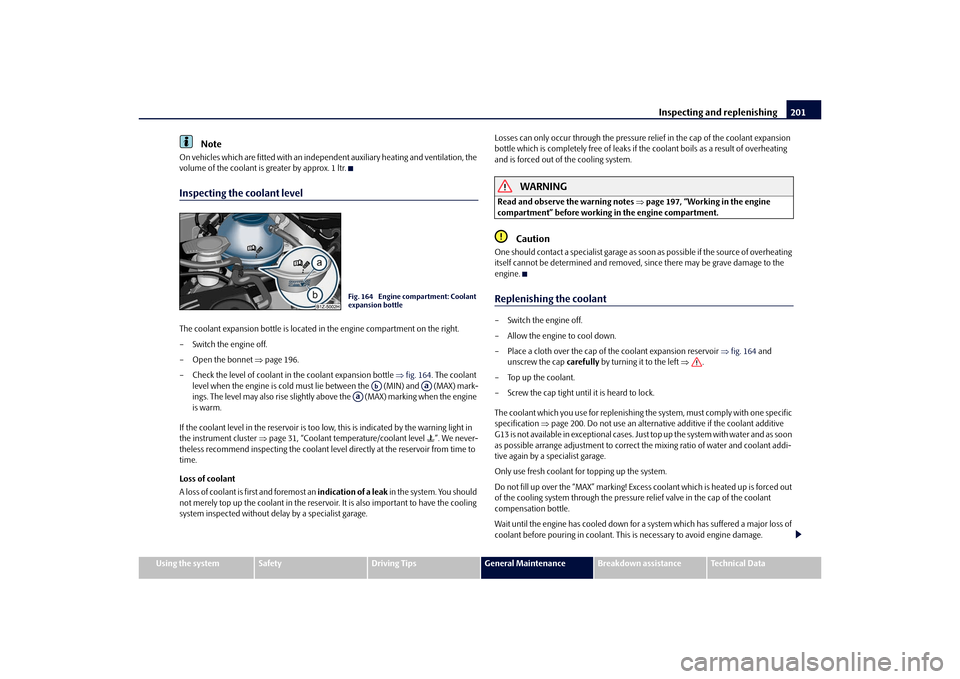
volume of the coolant is greater by approx. 1 ltr.Inspecting the coolant levelThe coolant expansion bottle is located in the engine compartment on the right.
– Switch the engine off.
– Open the bonnet page 196.
– Check the level of coolant in the coolant expansion bottle fig. 164 . The coolant
level when the engine is cold must lie between the (MIN) and (MAX) mark-
ings. The level may also rise slightly above the (MAX) marking when the engine
is warm.
If the coolant level in the reservoir is too lo w, this is indicated by the warning light in
the instrument cluster page 31, “Coolant temperature/coolant level ”. We never-
theless recommend inspecting the coolant leve l directly at the reservoir from time to
time.
Loss of coolant
A loss of coolant is first and foremost an indication of a leak in the system. You should
not merely top up the coolant in the reservoir. It is also important to have the cooling
system inspected without delay by a specialist garage. Losses can only occur through the pressure
relief in the cap of the coolant expansion
bottle which is completely free of leaks if the coolant boils as a result of overheating
and is forced out of the cooling system.
WARNING
Read and observe the warning notes page 197, “Working in the engine
compartment” before working in the engine compartment.
Caution
One should contact a specialist garage as s oon as possible if the source of overheating
itself cannot be determined and removed, since there may be grave damage to the
engine.Replenishing the coolant– Switch the engine off.
– Allow the engine to cool down.
– Place a cloth over the cap of the coolant expansion reservoir fig. 164 and
unscrew the cap carefully by turning it to the left .
–Top up the coolant.
– Screw the cap tight until it is heard to lock.
The coolant which you use for replenishing th e system, must comply with one specific
specification page 200. Do not use an alternative additive if the coolant additive
G13 is not available in exceptional cases. Just top up the system with water and as soon
as possible arrange adjustment to correct the mixing ratio of water and coolant addi-
tive again by a specialist garage.
Only use fresh coolant for topping up the system.
Do not fill up over the “MAX” marking! Excess coolant which is heated up is forced out
of the cooling system through the pressure relief valve in the cap of the coolant
compensation bottle.
Wait until the engine has cooled down for a system which has suffered a major loss of
coolant before pouring in coolant. This is necessary to avoid engine damage.
Fig. 164 Engine compartment: Coolant
expansion bottle
Ab
Aa
Aa
s43s.1.book Page 201 Thursday, May 13, 2010 1:21 PM
Page 228 of 275
Fuses and light bulbs227
Using the system
Safety
Driving Tips
General Maintenance
Breakdown assistance
Technical Data
Fuse cover in engine compartmentOn some vehicles, the battery cover must be removed before removing the fuse cover
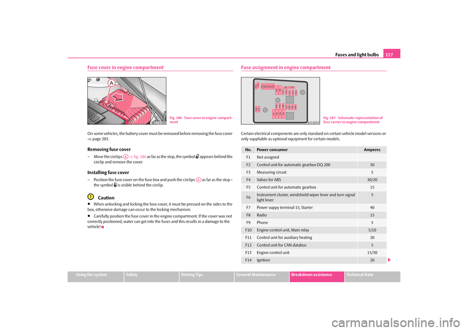
page 203.Removing fuse cover– Move the circlips fig. 186 as far as the stop, the symbol
appears behind the
circlip and remove the cover.
Installing fuse cover– Position the fuse cover on the fuse box and push the circlips as far as the stop -
the symbol
is visible behind the circlip.
Caution
When unlocking and locking the fuse cover, it must be pressed on the sides to the
box, otherwise damage can occur to the locking mechanism.
Carefully position the fuse cover in the engine compartment. If the cover was not
correctly positioned, water can get into the fuses and this results in a damage to the
vehicle!
Fuse assignment in engine compartmentCertain electrical components are only stan dard on certain vehicle model versions or
only suppliable as optional equipment for certain models.
Fig. 186 Fuse cover in engine compart-
ment
AA
AA
No.
Power consumer
Amperes
F1
Not assigned
F2
Control unit for automatic gearbox DQ 200
30
F3
Measuring circuit
5
F4
Valves for ABS
30/20
F5
Control unit for automatic gearbox
15
F6
Instrument cluster, windshield wiper lever and turn signal
light lever
5
F7
Power suppy terminal 15, Starter
40
F8
Radio
15
F9
Phone
5
F10
Engine control unit, Main relay
5/10
F11
Control unit for auxiliary heating
20
F12
Control unit for CAN databus
5
F13
Engine control unit
15/30
F14
Ignition
20
Fig. 187 Schematic representation of
fuse carrier in engine compartment
s43s.1.book Page 227 Thursday, May 13, 2010 1:21 PM
Page 229 of 275
Fuses and light bulbs
228
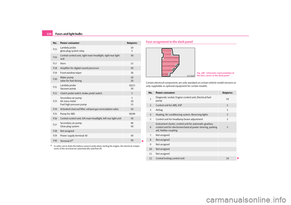
Fuse assignment in the dash panelCertain electrical components are only stan dard on certain vehicle model versions or
only suppliable as optional equipment for certain models.
F15
Lambda probe
glow plug system relay
10
5
F16
Central control unit, right main headlight, right rear light
unit
30
F17
Horn
15
F18
Amplifier for digital sound processor
30
F19
Front window wiper
30
F20
Wa te r pump
valve for fuel dosing
10
20
F21
Lambda probe
Vacuum pump
10/15 20
F22
Clutch pedal switch, brake pedal switch
5
F23
Secondary air pump
Air mass meter
Fuel high pressure pump
5
10
15
F24
Activated charcoal filter, ex haust gas recirculation valve
10
F25
Pump for ABS
30/40
F26
Central control unit, left main headlight, left rear light unit
30
F27
Secondary air pump
Glow plug system
40
50
F28
Not assigned
F29
Power supply terminal 30
50
F30
Te r m i n a l X
a)
50
a)In order not to drain the battery unnecessarily wh en starting the engine, the electrical compo-
nents of this terminal are automatically switched off.No.
Power consumer
Amperes
No.
Power consumer
Amperes
1
Diagnostic socket, Engine co ntrol unit, Electrical fuel
pump
10
2
Control unit for ABS, ESP
5
3
Airbag
5
4
Heating, Air conditioning system, Reversing lights
5
5
Control unit for headla mp beam adjustment
5
6
Instrument cluster, control unit for automatic gearbox,
control unit for electromecha nical power steering, parking
aid, Haldex coupling
5
7
Not assigned
8
Not assigned
9
Not assigned
10
Not assigned
11
Not assigned
12
Central locking control unit
10
Fig. 188 Schematic representation of
the fuse carrier in the dash panel
s43s.1.book Page 228 Thursday, May 13, 2010 1:21 PM
Page 266 of 275
Index265
Using the system
Safety
Driving Tips
General Maintenance
Breakdown assistance
Technical Data
ESP . . . . . . . . . . . . . . . . . . . . . . . . . . . . . . . . . . . . . . . . . 167
Warning light . . . . . . . . . . . . . . . . . . . . . . . . . . . . . 32
Exhaust gas Warning light . . . . . . . . . . . . . . . . . . . . . . . . . . . . . 30
Exhaust gas inspection Warning light . . . . . . . . . . . . . . . . . . . . . . . . . . . . . 30
Explanations . . . . . . . . . . . . . . . . . . . . . . . . . . . . . . . . . . . 6
Exterior mirror . . . . . . . . . . . . . . . . . . . . . . . . . . . . . . . . 65
Exterior mirror heater . . . . . . . . . . . . . . . . . . . . . . . . . 65
FFirst-aid box . . . . . . . . . . . . . . . . . . . . . . . . . . . . . . . . . 215
Fixing net Combi . . . . . . . . . . . . . . . . . . . . . . . . . . . . . . . . . . . . 76
Octavia . . . . . . . . . . . . . . . . . . . . . . . . . . . . . . . . . . . 76
Fog lights . . . . . . . . . . . . . . . . . . . . . . . . . . . . . . . . . . . . . 54 Indicator light . . . . . . . . . . . . . . . . . . . . . . . . . . . . . 29
Warning light . . . . . . . . . . . . . . . . . . . . . . . . . . . . . 29
Fog lights with the function CORNER . . . . . . . . . . . 55
Front airbag . . . . . . . . . . . . . . . . . . . . . . . . . . . . . . . . . 151
Front armrest . . . . . . . . . . . . . . . . . . . . . . . . . . . . . . . . . 89
Fuel . . . . . . . . . . . . . . . . . . . . . . . . . . . . . . . . . . . . . . . . . 192 Diesel fuel . . . . . . . . . . . . . . . . . . . . . . . . . . . . . . . 194
Fuel gauge . . . . . . . . . . . . . . . . . . . . . . . . . . . . . . . . 16
Petrol . . . . . . . . . . . . . . . . . . . . . . . . . . . . . . . . . . . 192
Fuel consumption . . . . . . . . . . . . . . . . . . . . . . . . . . . 176 Saving energy . . . . . . . . . . . . . . . . . . . . . . . . . . . . 176
Fuel gauge . . . . . . . . . . . . . . . . . . . . . . . . . . . . . . . . . . . 16
Fuel reserve Warning light . . . . . . . . . . . . . . . . . . . . . . . . . . . . . 35
Full wheel trim . . . . . . . . . . . . . . . . . . . . . . . . . . . . . . . 218
Fuses . . . . . . . . . . . . . . . . . . . . . . . . . . . . . . . . . . . . . . . 226
GGearbox mechanical . . . . . . . . . . . . . . . . . . . . . . . . . . . . . . 110
General view Cockpit . . . . . . . . . . . . . . . . . . . . . . . . . . . . . . . . . . . . 9
Glass roof . . . . . . . . . . . . . . . . . . . . . . . . . . . . . . . . . . . . 48
Glow plug system . . . . . . . . . . . . . . . . . . . . . . . . . . . . 109 Warning light . . . . . . . . . . . . . . . . . . . . . . . . . . . . . . 31
GSM . . . . . . . . . . . . . . . . . . . . . . . . . . . . . . . . . . . 125, 132HHandbrake . . . . . . . . . . . . . . . . . . . . . . . . . . . . . . . . . . 110
Hazard warning light system . . . . . . . . . . . . . . . . . . . 56 Warning light . . . . . . . . . . . . . . . . . . . . . . . . . . . . . . 28
Head airbag . . . . . . . . . . . . . . . . . . . . . . . . . . . . . . . . . 155
Head restraint . . . . . . . . . . . . . . . . . . . . . . . . . . . . . . . . 70
Headlamp range adjustment . . . . . . . . . . . . . . . . . . . 56
Headlight cleaning system . . . . . . . . . . . . . . . . . . . . . 63
Headlight flasher . . . . . . . . . . . . . . . . . . . . . . . . . . . . . . 57
Headlights Fog lights . . . . . . . . . . . . . . . . . . . . . . . . . . . . . . . . . 54
Headlight cleaning system . . . . . . . . . . . . . . . . . . 63
Heated windscreen washer nozzles . . . . . . . . . . . . . 61
Heating . . . . . . . . . . . . . . . . . . . . . . . . . . . . . . . . . . . . . . 95 Auxiliary heating (auxiliary heating) . . . . . . . . 104
Defrosting windows . . . . . . . . . . . . . . . . . . . . . . . 96
Recirculated air mode . . . . . . . . . . . . . . . . . . . . . 97
Horn . . . . . . . . . . . . . . . . . . . . . . . . . . . . . . . . . . . . . . . . . . 9
IIgnition . . . . . . . . . . . . . . . . . . . . . . . . . . . . . . . . . . . . . 107
Ignition lock . . . . . . . . . . . . . . . . . . . . . . . . . . . . . . . . 107
Immobiliser . . . . . . . . . . . . . . . . . . . . . . . . . . . . . . . . . . . 38
Information display . . . . . . . . . . . . . . . . . . . . . . . . . . . 22
Instrument cluster . . . . . . . . . . . . . . . . . . . . . . . . . . . . . 15
Instrument lighting . . . . . . . . . . . . . . . . . . . . . . . . . . . . 55
Interior light Luggage compartment . . . . . . . . . . . . . . . . . . . . . 59
Interior lighting . . . . . . . . . . . . . . . . . . . . . . . . . . . . . . . 58 front . . . . . . . . . . . . . . . . . . . . . . . . . . . . . . . . . . . . . . 58
rear . . . . . . . . . . . . . . . . . . . . . . . . . . . . . . . . . . . . . . . 58
Interior mirror . . . . . . . . . . . . . . . . . . . . . . . . . . . . . . . . 64
Interior monitor . . . . . . . . . . . . . . . . . . . . . . . . . . . . . . . 45
Intermittent wiping . . . . . . . . . . . . . . . . . . . . . . . . . . . . 61
ISOFIX . . . . . . . . . . . . . . . . . . . . . . . . . . . . . . . . . . . . . . 164
ISOFIX system . . . . . . . . . . . . . . . . . . . . . . . . . . . . . . . 164JJacking points . . . . . . . . . . . . . . . . . . . . . . . . . . . . . . . 220
Jump-starting . . . . . . . . . . . . . . . . . . . . . . . . . . . 221, 222KKey . . . . . . . . . . . . . . . . . . . . . . . . . . . . . . . . . . . . . . . . . . 37LLashing eyes . . . . . . . . . . . . . . . . . . . . . . . . . . . . . . . . . . 75
Leather care . . . . . . . . . . . . . . . . . . . . . . . . . . . . . . . . 190
Lifting jack . . . . . . . . . . . . . . . . . . . . . . . . . . . . . . 216, 220
s43s.1.book Page 265 Thursday, May 13, 2010 1:21 PM