stop start SKODA OCTAVIA 2010 2.G / (1Z) Owner's Guide
[x] Cancel search | Manufacturer: SKODA, Model Year: 2010, Model line: OCTAVIA, Model: SKODA OCTAVIA 2010 2.G / (1Z)Pages: 275, PDF Size: 16.43 MB
Page 224 of 275

Breakdown assistance223
Using the system
Safety
Driving Tips
General Maintenance
Breakdown assistance
Technical Data
– Take the vehicle out of gear or move the selector lever into position
N if your
vehicle is fitted with an automatic gearbox.
– Note that the brake servo unit and power steering only operate if the engine is running. You will require significantly grea ter physical force to depress the brake
pedal and to steer th e vehicle if the engine is not running.
– Ensure that the tow rope is always kept taught.
Tow rope or tow bar
A tow bar is safest way of towing a vehicle an d also minimizes any shocks. You can use
a tow rope only if a suitable tow bar is not available.
The tow rope must be elastic to protect the vehicle. Thus one should only use plastic
fibre rope or a rope made out of a similarly elastic material.
Only attach the tow rope to the towing eyes provided for this purpose page 223
and page 224.
Driving style
Towing another vehicle requires a certain am ount of practice. Both drivers should be
familiar with the particular points about to wing a vehicle. Unskilled drivers should not
attempt to tow in another vehicle or to be towed in.
One should be constantly vigi lant not to allow impermissibly high towing forces or
jerky loadings. There is always a risk of excessive stresses and damage resulting at the
points to which you attach the tow rope or tow bar when you attempt to tow a vehicle
which is not standing on a paved road.
Caution
If the gearbox of your vehicle no longer contains any oil because of a defect, your
vehicle must only be towed in with the driven wheels raised clear of the ground, or on
a special vehicle transporter or trailer.
Note
Please comply with any national legal provisions particularly regarding the
switched on signal systems, when towi ng in or tow-starting another vehicle.
The tow rope must not be twisted as it ma y in certain circumstances result in the
front towing eye being unscrewed out of your vehicle.
Front towing eye
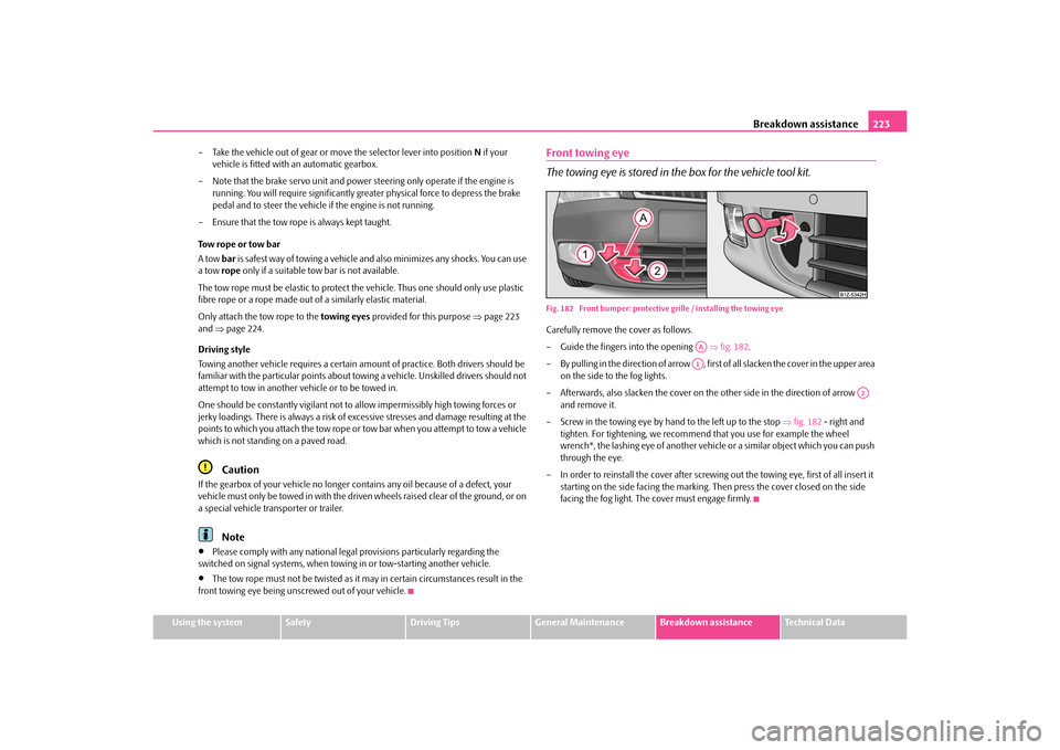
The towing eye is stored in th e box for the vehicle tool kit.Fig. 182 Front bumper: protective gr ille / installing the towing eyeCarefully remove the cover as follows.
– Guide the fingers into the opening fig. 182 .
– By pulling in the direction of arrow , first of all slacken the cover in the upper area on the side to the fog lights.
– Afterwards, also slacken the cover on th e other side in the direction of arrow
and remove it.
– Screw in the towing eye by hand to the left up to the stop fig. 182 - right and
tighten. For tightening, we recommen d that you use for example the wheel
wrench*, the lashing eye of another vehicl e or a similar object which you can push
through the eye.
– In order to reinstall the cover after screwing out the towing eye, first of all insert it
starting on the side facing the marking. Then press the cover closed on the side
facing the fog light. The cover must engage firmly.
AAA1
A2
s43s.1.book Page 223 Thursday, May 13, 2010 1:21 PM
Page 225 of 275

Breakdown assistance
224
Front towing eye for Octavia RS and Octavia Scout
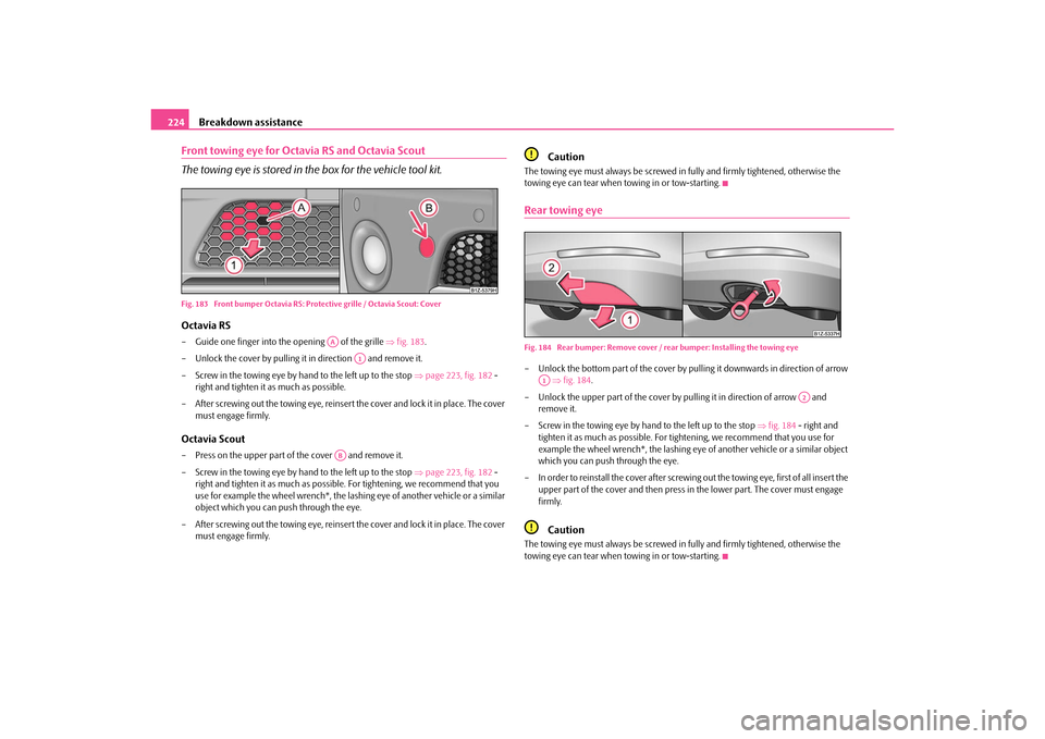
The towing eye is stored in th e box for the vehicle tool kit.Fig. 183 Front bumper Octavia RS: Protective grille / Octavia Scout: CoverOctavia RS– Guide one finger into the opening of the grille fig. 183 .
– Unlock the cover by pulling it in direction and remove it.
– Screw in the towing eye by hand to the left up to the stop page 223, fig. 182 -
right and tighten it as much as possible.
– After screwing out the towing eye, reinsert the cover and lock it in place. The cover must engage firmly.Octavia Scout– Press on the upper part of the cover and remove it.
– Screw in the towing eye by hand to the left up to the stop page 223, fig. 182 -
right and tighten it as much as possible. For tightening, we recommend that you
use for example the wheel wrench*, the lashing eye of another vehicle or a similar
object which you can push through the eye.
– After screwing out the towing eye, reinsert the cover and lock it in place. The cover must engage firmly.
Caution
The towing eye must always be screwed in fully and firmly tightened, otherwise the
towing eye can tear when towing in or tow-starting.Rear towing eyeFig. 184 Rear bumper: Remove cover / re ar bumper: Installing the towing eye– Unlock the bottom part of the cover by pulling it downwards in direction of arrow
fig. 184 .
– Unlock the upper part of the cover by pulling it in direction of arrow and remove it.
– Screw in the towing eye by hand to the left up to the stop fig. 184 - right and
tighten it as much as po ssible. For tightening, we recommend that you use for
example the wheel wrench*, the lashing eye of another vehicle or a similar object
which you can push through the eye.
– In order to reinstall the cover after screwing out the towing eye, first of all insert the
upper part of the cover and then press in the lower part. The cover must engage
firmly.
Caution
The towing eye must always be screwed in fully and firmly tightened, otherwise the
towing eye can tear when towing in or tow-starting.
AA
A1
AB
A1
A2
s43s.1.book Page 224 Thursday, May 13, 2010 1:21 PM
Page 228 of 275

Fuses and light bulbs227
Using the system
Safety
Driving Tips
General Maintenance
Breakdown assistance
Technical Data
Fuse cover in engine compartmentOn some vehicles, the battery cover must be removed before removing the fuse cover
page 203.Removing fuse cover– Move the circlips fig. 186 as far as the stop, the symbol
appears behind the
circlip and remove the cover.
Installing fuse cover– Position the fuse cover on the fuse box and push the circlips as far as the stop -
the symbol
is visible behind the circlip.
Caution
When unlocking and locking the fuse cover, it must be pressed on the sides to the
box, otherwise damage can occur to the locking mechanism.
Carefully position the fuse cover in the engine compartment. If the cover was not
correctly positioned, water can get into the fuses and this results in a damage to the
vehicle!
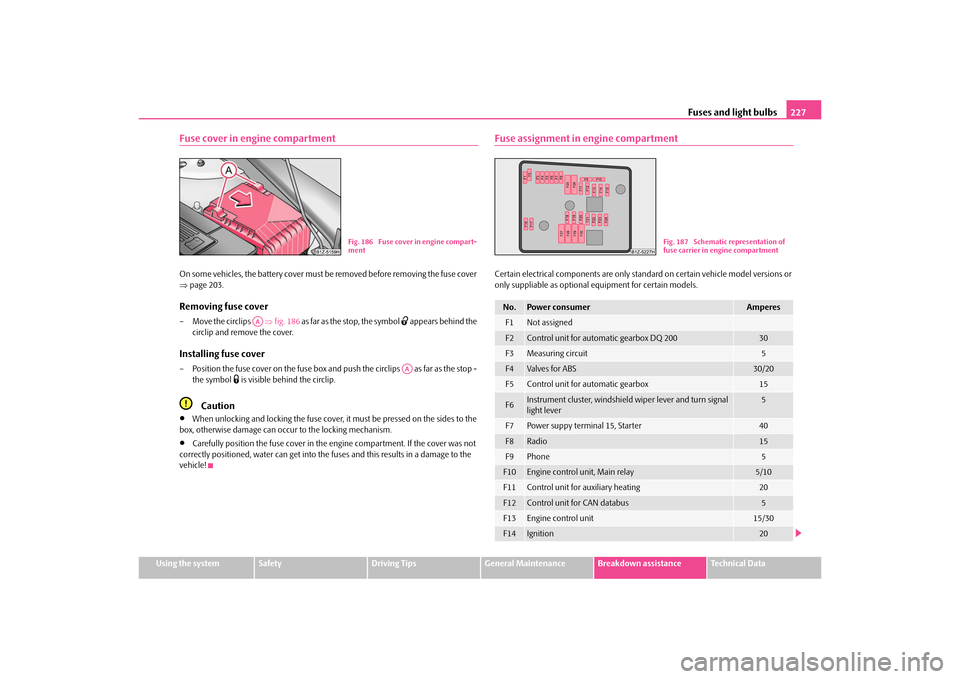
Fuse assignment in engine compartmentCertain electrical components are only stan dard on certain vehicle model versions or
only suppliable as optional equipment for certain models.
Fig. 186 Fuse cover in engine compart-
ment
AA
AA
No.
Power consumer
Amperes
F1
Not assigned
F2
Control unit for automatic gearbox DQ 200
30
F3
Measuring circuit
5
F4
Valves for ABS
30/20
F5
Control unit for automatic gearbox
15
F6
Instrument cluster, windshield wiper lever and turn signal
light lever
5
F7
Power suppy terminal 15, Starter
40
F8
Radio
15
F9
Phone
5
F10
Engine control unit, Main relay
5/10
F11
Control unit for auxiliary heating
20
F12
Control unit for CAN databus
5
F13
Engine control unit
15/30
F14
Ignition
20
Fig. 187 Schematic representation of
fuse carrier in engine compartment
s43s.1.book Page 227 Thursday, May 13, 2010 1:21 PM
Page 235 of 275

Fuses and light bulbs
234
– In order to reinstall the cover, first of all insert one part of the cover starting on the
side facing the marking. Then press the cove r closed on the side facing the fog light.
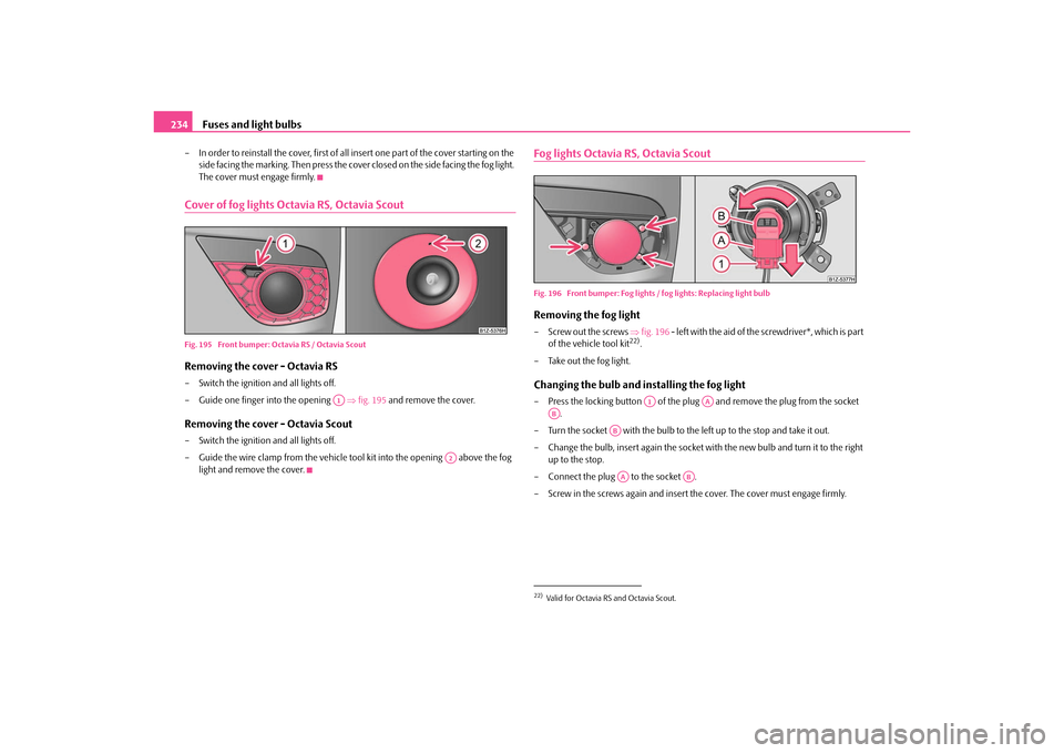
The cover must engage firmly.Cover of fog lights Octavia RS, Octavia ScoutFig. 195 Front bumper: Octavia RS / Octavia ScoutRemoving the cover - Octavia RS– Switch the ignition and all lights off.
– Guide one finger into the opening fig. 195 and remove the cover.Removing the cover - Octavia Scout– Switch the ignition and all lights off.
– Guide the wire clamp from the vehicle tool kit into the opening above the fog
light and remove the cover.
Fog lights Octavia RS, Octavia ScoutFig. 196 Front bumper: Fog lights / fog lights: Replacing light bulbRemoving the fog light–Screw out the screws fig. 196 - left with the aid of the screwdriver*, which is part
of the vehicle tool kit
22).
– Take out the fog light.
Changing the bulb and installing the fog light– Press the locking button of the plug and remove the plug from the socket
.
– Turn the socket with the bulb to the left up to the stop and take it out.
– Change the bulb, insert again the socket wi th the new bulb and turn it to the right
up to the stop.
– Connect the plug to the socket .
– Screw in the screws again and insert the cover. The cover must engage firmly.
A1
A2
22)Valid for Octavia RS and Octavia Scout.
A1
AA
AB
ABAA
AB
s43s.1.book Page 234 Thursday, May 13, 2010 1:21 PM