technical data SKODA OCTAVIA 2010 2.G / (1Z) Service Manual
[x] Cancel search | Manufacturer: SKODA, Model Year: 2010, Model line: OCTAVIA, Model: SKODA OCTAVIA 2010 2.G / (1Z)Pages: 275, PDF Size: 16.43 MB
Page 82 of 275
Seats and Stowage81
Using the system
Safety
Driving Tips
General Maintenance
Breakdown assistance
Technical Data
Pay attention that the rear seat backrest is correctly interlocked. It is only
then that the three-point seat belt for th e middle seat can reliably fulfil its func-
tion.
First check for yourself that the cross road is inserted into the mounts in
the front position!
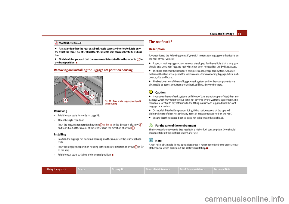
Removing and installing the luggage net partition housingRemoving– Fold the rear seats forwards page 72.
– Open the right rear door.
– Push the luggage net partition housing fig. 78 in the direction of arrow
and take it out of the mount of the rear seats in the direction of arrow .Installing– Position the luggage net partition housing into the mounts in the rear seat back- rests.
– Push the luggage net partition housing in the opposite direction of arrow as far as the stop.
– Fold the rear seats back into their original position.
The roof rack*DescriptionPay attention to the following points if you wish to transport luggage or other items on
the roof of your vehicle:
A special roof luggage rack system was de veloped for the vehicle, that is why you
should only use a roof luggage rack which has been released for use by Škoda Auto.
The base carrier is the basis for a comple te roof luggage rack system. Separate
additional holders are required for safety reasons for transporting luggage, bikes, surf-
boards, skis and boats.
The basic version of the roof luggage rack system and further components are
obtainable as accessories from the authorised Škoda Service Partners.Caution
If you use other roof rack systems or if the roof bars are not properly fitted, then any
damage which may result to your car is not covered by the warranty agreements. It is
therefore essential to pay attention to the fitting instructions supplied with the roof
luggage rack system.
On models fitted with a power sliding/ tilting roof, ensure that the opened
sliding/tilting roof does not strike any items of luggage transported on the roof.
Ensure that the opened boot lid do es not collide with the roof load.For the sake of the environment
The increased aerodynamic drag results in a higher fuel consumption. One should
therefore take off the roof bar system after use.
Note
A roof rail is obtainable from a specialist garage if hasn't been fitted onto an estate car
at the works, which carries out the professional fitting.
WARNING (continued)
AC
Fig. 78 Rear seats: Luggage net parti-
tion housing
AA
A1
A2A1
s43s.1.book Page 81 Thursday, May 13, 2010 1:21 PM
Page 84 of 275

Seats and Stowage83
Using the system
Safety
Driving Tips
General Maintenance
Breakdown assistance
Technical Data
Cup holder in rear centre console*– Press on the panel in the area fig. 81 - the cup holder comes out.
– Pull the cup holder out as far as the stop.
– Adjust the cup holder by moving the locking plate .
WARNING
Do not place any hot beverages into th e cup holder while the car is moving.
The hot beverages may spill - risk of scalding!
Do not use any cups or beakers which are made of brittle material (e.g. glass,
porcelain). You might be injured by them in the event of an accident.
Note holder
The note holder is designed e.g. for attaching a car park ticket in parking areas.
The attached note has to always be removed before starting off in order not to restrict
the driver's vision.Ashtray*Front ashtrayFig. 83 Centre console: Front ashtray / remove front ashtray insertOpening ashtray– Press on the bottom part of the cover of the ashtray - refer to fig. 83 .Removing ashtray insert– Press on the ashtray insert in the area (the insert comes out) and you can take
it out.Insert ashtray insert– Insert the ashtray insert into the mount and press it in.
WARNING
Never lay flammable objects in the ashtray basin - risk of fire!
Fig. 81 Centre console at rear: Cup
holder
AA
AB
Fig. 82 Windscreen: Note holder
AA
AB
s43s.1.book Page 83 Thursday, May 13, 2010 1:21 PM
Page 86 of 275
Seats and Stowage85
Using the system
Safety
Driving Tips
General Maintenance
Breakdown assistance
Technical Data
Cigarette lighter*, power socketsCigarette lighter
You can also use the socket on the ci garette lighter for other electrical
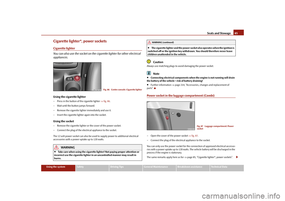
appliances.Using the cigarette lighter– Press in the button of the cigarette lighter fig. 86 .
– Wait until the button jumps forward.
– Remove the cigarette lighter immediately and use it.
– Insert the cigarette lighter again into the socket.Using the socket– Remove the cigarette lighter or the cover of the power socket.
– Connect the plug of the electrical appliance to the socket.
The 12 volt power socket can also be used to supply power to additional electrical
accessories with a power uptake up to 120 watts.
WARNING
Take care when using the cigarette ligh ter! Not paying proper attention or
incorrect use the cigarette lighter in an uncontrolled manner may result in
burns.
The cigarette lighter and the power socket also operates when the ignition is
switched off or the ignition key withdrawn. You should therefore never leave
children unattended in the vehicle.Caution
Always use matching plugs to av oid damaging the power socket.
Note
Connecting electrical components when the engine is not running will drain
the battery of the vehicle - risk of battery draining!
Further information page 214, “Accessories, changes and replacement of
parts”.
Power socket in the luggage compartment (Combi)– Open the cover of the power socket fig. 87 .
– Connect the plug of the electrical appliance to the socket.
You can only use the power socket for the connection of approved electrical accesso-
ries with a power uptake up to 120 watts. The vehicle battery will be discharged in the
process if the engine is stationary.
The same remarks apply here as for page 85, “Cigarette lighter*, power sockets”.
Fig. 86 Centre console: Cigarette lighter
WARNING (continued)
Fig. 87 Luggage compartment: Power
socket
s43s.1.book Page 85 Thursday, May 13, 2010 1:21 PM
Page 88 of 275
Seats and Stowage87
Using the system
Safety
Driving Tips
General Maintenance
Breakdown assistance
Technical Data
Cooling of storage compartment on front passenger side*The storage compartment is for vehicles fitted with an air-conditioning
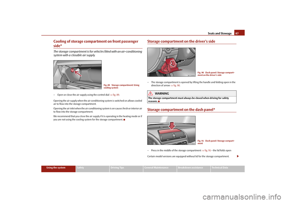
system with a closable air supply.– Open or close the air supp ly using the control dial fig. 89 .
Opening the air supply when the air conditioni ng system is switched on allows cooled
air to flow into the storage compartment.
Opening the air inlet when the air conditioning system is on causes fresh or interior air
to flow into the storage compartment.
We recommend that you close the air supply if it is operating in the heating mode or if
you are not using the cooling system for the storage compartment.
Storage compartment on the driver's side– The storage compartment is opened by li fting the handle and folding open in the
direction of arrow fig. 90 .
WARNING
The storage compartment must always be closed when driving for safety
reasons.Storage compartment on the dash panel*– Press in the middle of the storage compartment fig. 91 - the lid folds open
Certain model versions are equipped without lid for the storage compartment.
Fig. 89 Storage compartment: Using
cooling system
Fig. 90 Dash panel: Storage compart-
ment on the driver's sideFig. 91 Dash panel: Storage compart-
ment
s43s.1.book Page 87 Thursday, May 13, 2010 1:21 PM
Page 90 of 275
Seats and Stowage89
Using the system
Safety
Driving Tips
General Maintenance
Breakdown assistance
Technical Data
WARNING
The compartment must only be opened when removing or inserting objects
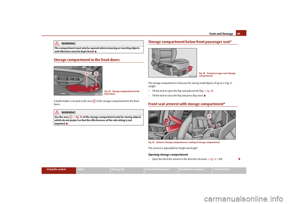
and otherwise must be kept closed.Storage compartment in the front doorsA bottle holder is located in the area of the storage compartment for the front
doors.
WARNING
Use the area fig. 95 of the storage compartment only for storing objects
which do not project so that the effectiveness of the side airbag is not
impaired.
Storage compartment below front passenger seat*The storage compartment is foreseen for storing small objects of up to 1.5 kg. in
weight.
– Tilt the lock to open the flap and pull out the flap fig. 96 .
– Tilt the lock to close the flap and press flap close.Front seat armrest with storage compartment*Fig. 97 Armrest: Storage compartment / cooling of storage compartmentThe armrest is adjustable for height and length.Opening storage compartment– Open the lid of the armrest in the direction of arrow fig. 97 - left.
Fig. 95 Storage compartment in the
front doors
AB
AA
Fig. 96 Front passenger seat: Storage
compartment
s43s.1.book Page 89 Thursday, May 13, 2010 1:21 PM
Page 92 of 275

Seats and Stowage91
Using the system
Safety
Driving Tips
General Maintenance
Breakdown assistance
Technical Data
Seat backrest with opening for skis*Fig. 100 Rear seats: Handle of lid / luggage compartment: Unlock buttonAfter folding open the armrest and the lid, an opening in the seat backrest becomes
visible through which you can push long objects e.g. skis etc. You can fold open the
armrest and the lid from the passenger or luggage compartment.Opening from passenger compartment– Fold down the armrest of the rear seat at the loop page 73.
– Pull the handle up to the stop in upward direction and fold open the lid downwards fig. 100 - left.Opening from luggage compartment– Push the unlock button downwards fig. 100 - right and fold the lid (with armrest)
to the front.Closing– Fold the lid and the armrest up to the stop in upward direction - the lid must click into place audibly.
Ensure that the armrest is always locked into place after closing. You can recognize this
on the fact that the red field above the unlocking button of the luggage compart-
ment is not visible.
Removeable through-loading bag*The removeable through-loading bag is solely used for transporting
skis.Loading– Open the boot lid.
– Fold the rear armrest and the cover in the seat backrest downwards page 91,
“Seat backrest with opening for skis*”.
– Place the empty through-loadi ng bag in such a way that the end of the bag with the
zip lies in the boot.
– Push the skis into the through-loadi ng bag from the luggage compartment .Securing– Tighten the strap on the free end around the skis in front of the bindings
fig. 101 .
– Fold the seat backrest a little forward.
– Guide the securing strap through the op ening in the seat backrest around the
upper part of the seat backrest.
– Then push the seat backrest back into th e upright position until the locking button
clicks into place - check by pulling on the seat backrest.
– Insert the securing strap into the lock until it is heard to lock in place.
AA
Fig. 101 Securing the removeable
through-loading bag
AA
ABAB
AC
s43s.1.book Page 91 Thursday, May 13, 2010 1:21 PM
Page 94 of 275
Seats and Stowage93
Using the system
Safety
Driving Tips
General Maintenance
Breakdown assistance
Technical Data
Clothes hooks*The clothes hooks are located on the middle pillar and on the handle of the headliner
above each of the rear doors.
WARNING
Ensure that any clothes hanging from the hooks do not impair your vision to
the rear.
Use the hooks for hanging only light item s of clothing and ensure that there
are no heavy or sharp-edge d objects in the pockets.
The maximum permissable load of the hooks is 2 kg.
Do not use clothes hangers for hanging up items of clothing otherwise this
will interfere with the protection offered by the head airbag*.
s43s.1.book Page 93 Thursday, May 13, 2010 1:21 PM
Page 96 of 275
Heating and air conditioning system95
Using the system
Safety
Driving Tips
General Maintenance
Breakdown assistance
Technical Data
HeatingUsing the system
The heating system delivers air into the interior of the vehicle and
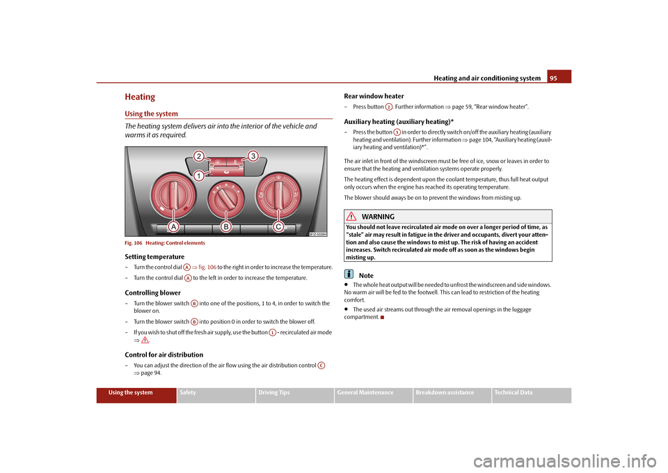
warms it as required.Fig. 106 Heating: Control elementsSetting temperature– Turn the control dial fig. 106 to the right in order to increase the temperature.
– Turn the control dial to the left in order to increase the temperature.Controlling blower– Turn the blower switch into one of the po sitions, 1 to 4, in order to switch the
blower on.
– Turn the blower switch into position 0 in order to switch the blower off.
– If you wish to shut off the fresh air supply , use the button - recirculated air mode
.Control for air distribution– You can adjust the direction of the air flow using the air distribution control
page 94.
Rear window heater– Press button . Further information page 59, “Rear window heater”.Auxiliary heating (auxiliary heating)*– Press the button in order to directly switch on/off the auxiliary heating (auxiliary
heating and ventilation). Further information page 104, “Auxiliary heating (auxil-
iary heating and ventilation)*”.
The air inlet in front of the windscreen must be free of ice, snow or leaves in order to
ensure that the heating and ventilation systems operate properly.
The heating effect is dependent upon the c oolant temperature, thus full heat output
only occurs when the engine has reached its operating temperature.
The blower should aways be on to prevent the windows from misting up.
WARNING
You should not leave recirculated air mode on over a longer period of time, as
“stale” air may result in fatigue in the driver and occupants, divert your atten-
tion and also cause the windows to mist up. The risk of having an accident
increases. Switch recirculated air mo de off as soon as the windows begin
misting up.
Note
T h e w h o l e h e a t o u t p u t w i l l b e n e e d e d t o u n f ro s t t h e w i n d s c re e n a n d s i d e w i n d o w s .
No warm air will be fed to the footwell. Th is can lead to restriction of the heating
comfort.
The used air streams out through the air removal openings in the luggage
compartment.
AAAAABAB
A1
AC
A2A3
s43s.1.book Page 95 Thursday, May 13, 2010 1:21 PM
Page 98 of 275
Heating and air conditioning system97
Using the system
Safety
Driving Tips
General Maintenance
Breakdown assistance
Technical Data
Recirculated air mode
In recirculated air mode air is sucked out of the interior of the vehicle
and then fed back into the interior.Recirculated air mode prevents polluted air outside the vehicle from getting into the
vehicle, for example when driving through a tunnel or when standi ng in a traffic jam.Switching recirculated air mode on– Press the button - the warning light lights up in the button page 95, fig. 106 .Switching recirculated air mode off– Press again the button - the warning light in the button goes out.
The recirculated air mode is switched off automatically if the air distribution control
is in position
page 95, fig. 106. You can also switch recirculated air mode on
again from this setting by repeatedly pressing button .
WARNING
You should not leave recirculated air mode on over a longer period of time, as
“stale” air may result in fatigue in the driver and occupants, divert your atten-
tion and also cause the windows to mist up. The risk of having an accident
increases. Switch recirculated air mode off as soon as the windows begin
misting up.Climatic* (semi-automatic air conditioning system)Description
The Climatic is a combined coolin g and heating system. It makes it
possible to optimally control the air temperature at any season of the
year.Description of the Climatic
It is important for your safety and for your driving comfort that the Climatic is operating
properly. The cooling only operates if button
page 98, fig. 107 is pressed, and the
following conditions are met:
engine running,
outside temperature above approx. +2°C and
blower switch switched on (positions 1 to 4).
If the cooling system is switched on, the temperature and air humidity drops in the
vehicle. The wellbeing of the occupants of the car is enhanced as a result of this partic-
ularly at high outside temperatures and a high air humidity. The system prevents the
windows misting up during the cold season of the year.
The heating effect is dependent upon the c oolant temperature, thus full heat output
only occurs when the engine has reached its operating temperature.
It is possible to briefly activate recirculat ed air mode in order to enhance the cooling
effect .
Air at a temperature of about 5°C may flow out of the vents under certain circum-
stances when the cooling system is operating. Lengthy and uneven distribution of the
air flow out of the vents and large differences in temperature, for example when getting
out of the vehicle, can result in chills in sensitive persons.
The air inlet in front of the windscreen must be free of ice, snow or leaves in order to
ensure that the heating and cooling systems operate properly.
After switching on the cooling Condensation from the evaporator of the air condi-
tioning may drip down and form a puddle be low the vehicle. This is quite normal and
not an indication of a leak!
WARNING
For your own safety and that of other road users, ensure that all the
windows are free of ice, snow and misting. Please familiarize yourself about
how to correctly operate the heating and ventilation systems, how to demist
and defrost the windows, as well as with the cooling mode.
You should not leave recirculated air mode on over a longer period of time,
as “stale” air may result in fatigue in the driver and occupants, divert your
attention and also cause the windows to mist up. The risk of having an accident
increases. Switch recirculated air mo de off as soon as the windows begin
misting up.
AC
AC
A1
s43s.1.book Page 97 Thursday, May 13, 2010 1:21 PM
Page 100 of 275
Heating and air conditioning system99
Using the system
Safety
Driving Tips
General Maintenance
Breakdown assistance
Technical Data
Please refer to the information regarding recirculated air mode page 100.
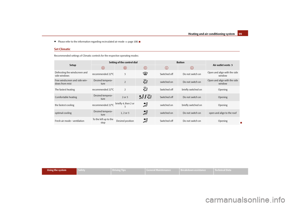
Set ClimaticRecommended settings of Climatic contro ls for the respective operating modes:
Setup
Setting of the control dial
Button
Air outlet vents 3
Defrosting the windscreen and
side windows
recommended 22°C
3
Switched off
Do not switch on
Open and align with the side
window
Free windscreen and side win-
dows from mist
Desired tempera-ture
2
switched on
Do not switch on
Open and align with the side window
The fastest heating
recommended 22°C
2
Switched off
briefly switched on
Opening
Comfortable heating
Desired tempera-
ture
2 or 3
Switched off
Do not switch on
Opening
the fastest cooling
recommended 22°C
briefly4, then 2or 3
switched on
briefly switched on
Opening
optimal cooling
Desired tempera-ture
1, 2 or 3
switched on
Do not switch on
open and align to the roof
Fresh air mode - ventilation
To the left up to the
stop
Desired position
Switched off
Do not switch on
Opening
AA
AB
AC
A1
A4
s43s.1.book Page 99 Thursday, May 13, 2010 1:21 PM