technical data SKODA OCTAVIA 2010 2.G / (1Z) Manual Online
[x] Cancel search | Manufacturer: SKODA, Model Year: 2010, Model line: OCTAVIA, Model: SKODA OCTAVIA 2010 2.G / (1Z)Pages: 275, PDF Size: 16.43 MB
Page 162 of 275
Transporting children safely161
Using the system
Safety
Driving Tips
General Maintenance
Breakdown assistance
Technical Data
You should have the front passenger airbag (or airbags) reactivated just as
soon as you no longer use a child safe ty seat on the front passenger seat.
Child safety and side airbag*
Children must never be seated in the deployment area of the side
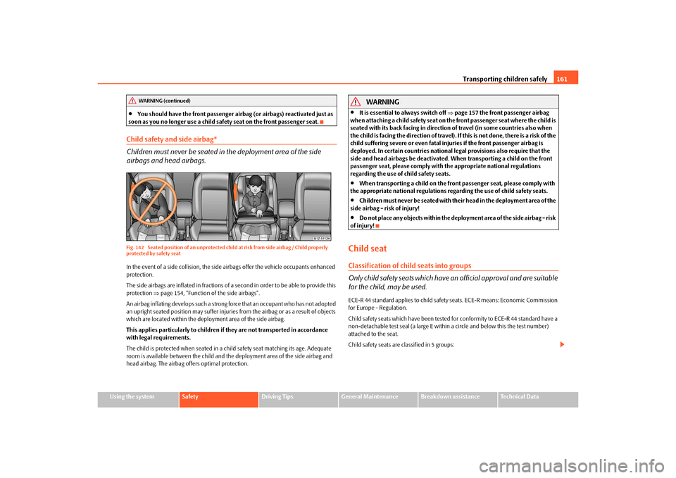
airbags and head airbags.Fig. 142 Seated position of an unprotected chil d at risk from side airbag / Child properly
protected by safety seatIn the event of a side collision, the side ai rbags offer the vehicle occupants enhanced
protection.
The side airbags are inflated in fractions of a second in order to be able to provide this
protection page 154, “Function of the side airbags”.
An airbag inflating develops such a strong force that an occupant who has not adopted
an upright seated position may suffer injuries from the airbag or as a result of objects
which are located within the deployment area of the side airbag.
This applies particularly to children if they are not transported in accordance
with legal requirements.
The child is protected when seated in a chil d safety seat matching its age. Adequate
room is available between the child and the deployment area of the side airbag and
head airbag. The airbag offers optimal protection.
WARNING
It is essential to always switch off page 157 the front passenger airbag
when attaching a child safety seat on th e front passenger seat where the child is
seated with its back facing in direction of travel (in some countries also when
the child is facing the direction of travel). If this is not done, there is a risk of the
child suffering severe or even fatal inju ries if the front passenger airbag is
deployed. In certain countries national legal provisions also require that the
side and head airbags be deactivated. When transporting a child on the front
passenger seat, please comply with the appropriate national regulations
regarding the use of child safety seats.
When transporting a child on the front passenger seat, please comply with
the appropriate national regulations r egarding the use of child safety seats.
Children must never be seated with thei r head in the deployment area of the
side airbag - risk of injury!
Do not place any objects within the deployment area of the side airbag - risk
of injury!
Child seatClassification of child seats into groups
Only child safety seats which have an official approval and are suitable
for the child, may be used.ECE-R 44 standard applies to child safety seats. ECE-R means: Economic Commission
for Europe - Regulation.
Child safety seats which have been tested for conformity to ECE-R 44 standard have a
non-detachable test seal (a large E within a circle and below this the test number)
attached to the seat.
Child safety seats are classified in 5 groups:
WARNING (continued)
s43s.1.book Page 161 Thursday, May 13, 2010 1:21 PM
Page 164 of 275
Transporting children safely163
Using the system
Safety
Driving Tips
General Maintenance
Breakdown assistance
Technical Data
You should have the front passenger airbag (or airbags) reactivated just as
soon as you no longer use a child safe ty seat on the front passenger seat.
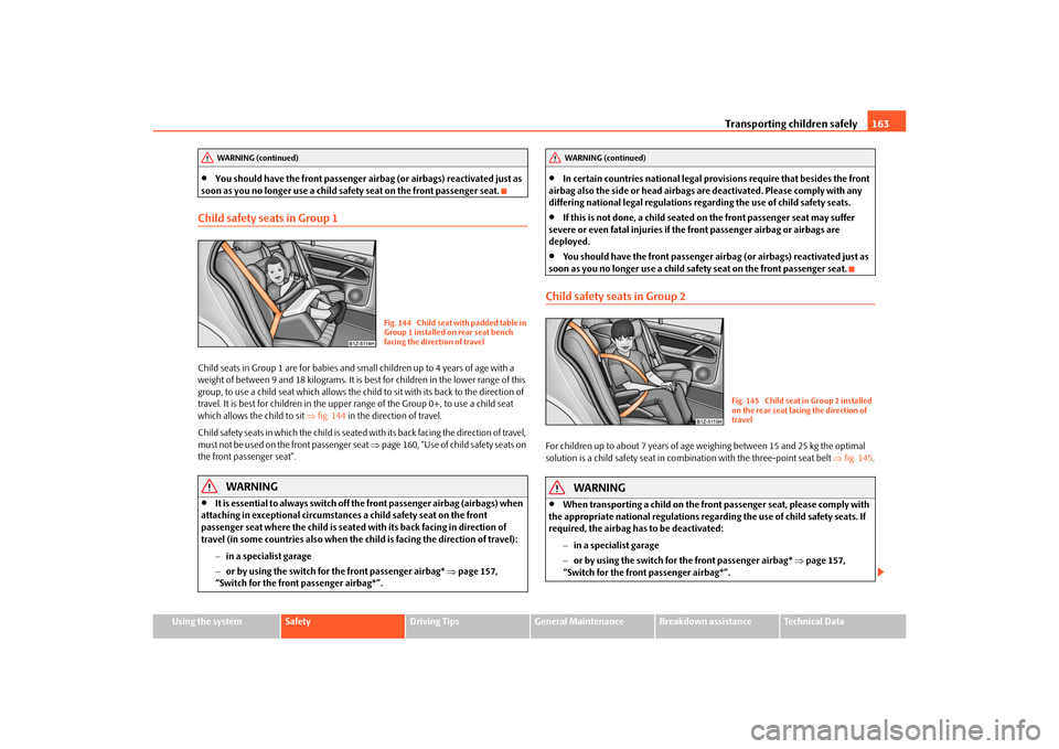
Child safety seats in Group 1Child seats in Group 1 are for babies and small children up to 4 years of age with a
weight of between 9 and 18 kilograms. It is best for children in the lower range of this
group, to use a child seat which allows the ch ild to sit with its back to the direction of
travel. It is best for children in the uppe r range of the Group 0+, to use a child seat
which allows the child to sit fig. 144 in the direction of travel.
Child safety seats in which the child is seated with its back facing the direction of travel,
must not be used on the front passenger seat page 160, “Use of child safety seats on
the front passenger seat”.
WARNING
It is essential to always switch off th e front passenger airbag (airbags) when
attaching in exceptional circumstances a child safety seat on the front
passenger seat where the child is seated with its back facing in direction of
travel (in some countries also when the child is facing the direction of travel):
in a specialist garage
or by using the switch for the front passenger airbag* page 157,
“Switch for the front passenger airbag*”.
In certain countries national legal provisions require that besides the front
airbag also the side or head airbags ar e deactivated. Please comply with any
differing national legal r egulations regarding the use of child safety seats.
If this is not done, a child seated on the front passenger seat may suffer
severe or even fatal injuries if the front passenger airbag or airbags are
deployed.
You should have the front passenger airbag (or airbags) reactivated just as
soon as you no longer use a child safe ty seat on the front passenger seat.
Child safety seats in Group 2For children up to about 7 years of age weighing between 15 and 25 kg the optimal
solution is a child safety seat in combination with the three-point seat belt fig. 145 .
WARNING
When transporting a child on the front passenger seat, please comply with
the appropriate national regulations regard ing the use of child safety seats. If
required, the airbag has to be deactivated:
in a specialist garage
or by using the switch for the front passenger airbag* page 157,
“Switch for the front passenger airbag*”.
WARNING (continued)
Fig. 144 Child seat with padded table in
Group 1 installed on rear seat bench
facing the direction of travel
WARNING (continued)
Fig. 145 Child seat in Group 2 installed
on the rear seat facing the direction of
travel
s43s.1.book Page 163 Thursday, May 13, 2010 1:21 PM
Page 166 of 275
Transporting children safely165
Using the system
Safety
Driving Tips
General Maintenance
Breakdown assistance
Technical Data
– Insert the mounting funnels onto the
locking eyes between the seat back-
rest and the seat cushion fig. 147 .
– Push the notched arms of the child seat in to the locking eyes in direction of arrow
, until they are heard to lock in place fig. 147 .
– Pull on both sides of the child seat!
One can mount a child safety seat using the “I SOFIX” system quickly, easily and reliably.
Please pay close attention to instructions from the manufacturer of the child safety
seat when installing and removing the seat.
Child seats fitted with the “ISOFIX” system can only be mounted and fixed in a vehicle
fitted with an “ISOFIX” system when these child seats have been released for this type
of vehicle according to the ECE-R 44 standard.
You can obtain child seats with the “ISOFIX” attachment system from specialist garages
who will also installed it as well.
Complete installation instructions are enclosed with the child safety seat.
WARNING
The locking eyes have just been deve loped for child safety seats which use
the “ISOFIX” system. You should therefore never attach other child safety seats,
seat belts or objects to the locking eyes - hazard!
Ask an authorised Škoda Service Part ner whether a child seat which you
bought for another vehicle is recommended for use in a Škoda before using an
“ISOFIX” system.
Certain child seats which use the “ISO FIX” system can be attached with
standard three-point seat belts. Please pay close attention to instructions from
the manufacturer of the child safety seat when installing and removing the seat.Note
Child seats which use the “ISOFIX” system are currently available for children
weighing from 9 up to 18 kg. This correspond s to an age range of from 9 months to 4
years.
The child seats can also be fitted with the “Top Tether” system page 165.
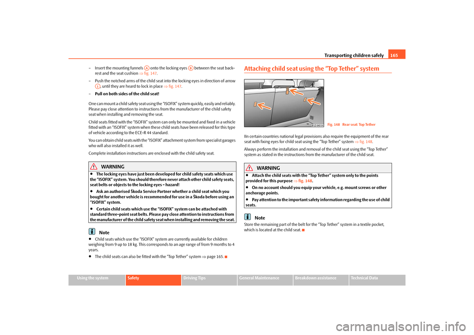
Attaching child seat using the “Top Tether” systemIIn certain countries national legal provisions also require the equipment of the rear
seat with fixing eyes for child seat using the “Top Tether” system fig. 148 .
Always perform the installation and removal of the child seat using the “Top Tether”
system as stated in the instructions from the manufacturer of the child seat.
WARNING
Attach the child seats with the “Top Tether” system only to the points
provided for this purpose fig. 148 .
On no account should you equip your vehicle, e.g. mount screws or other
anchorage points.
Pay attention to the important safety information regarding the use of child
seats.Note
Store the remaining part of the belt for the “Top Tether” system in a textile pocket,
which is located at the child seat.
AA
AB
A1
Fig. 148 Rear seat: Top Tether
s43s.1.book Page 165 Thursday, May 13, 2010 1:21 PM
Page 168 of 275
Intelligent Technology167
Using the system
Safety
Driving Tips
General Maintenance
Breakdown assistance
Technical Data
Driving TipsIntelligent TechnologyElectronic stability programme (ESP)*GeneralThe ESP aids you in maintaining control of your vehicle in situations in which the
vehicle is driving at its dynamic limits, such as entering a curve fast. The risk of skidding
is reduced and your vehicle thus offers greater driving stability depending on the
conditions of the road surface. The system operates at all speeds.
The following systems are integrated into the electronic stability programme:
Electronic Differential Lock (EDL),
Traction control system (TCS),
active driver-steering recommendation (DSR),
Antilock brake system (ABS),
Brake Assist,
Uphill Start Assist
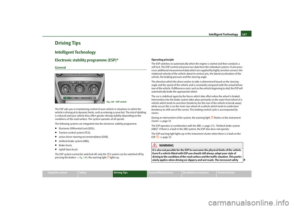
The ESP system cannot be switched off, only the TCS system can be switched off by
pressing the button fig. 149 , the warning light
lights up. Operating principle
The ESP switches on automatically when the engine is started and then conducts a
self-test. The ESP control unit processes data from the individual systems. It also proc-
esses additional measurement data which are supplied by highly sensitive sensors: the
rotational velocity of the vehicle about its ve
rtical axis, the lateral acceleration of the
vehicle, the braking pressure and the steering angle.
The direction which the driver wishes to take is determined based on the steering
angle and the speed of the vehicle and is co nstantly compared with the actual behav-
iour of the vehicle. If differences exist, such as the vehi cle beginning to skid, the ESP will
automatically brake the appropriate wheel.
The car is stabilised again by the forces wh ich take effect when the wheel is braked.
Intervention into the brake system takes place primarily on the outer front wheel of a
vehicle which tends to oversteer (tendency for the rear of the vehicle to break away)
while occurs this is on the inner rear wh eel of a vehicle which tends to understeer
(tendency to shift out of the curve). This braking control cycle is accompanied by
noises.
During an intervention of the system, the warning light
flashes in the instrument
cluster page 32.
The ESP operates in combination with the ABS page 171, “Antilock brake system
(ABS)”. If there is a fault in the ABS system, the ESP also does not operate.
The ESP warning light lights up in the instrument cluster when there is a fault on the
ESP
page 32.WARNING
It is also not possible for the ESP to overcome the physical limits of the vehicle.
Even if a vehicle fitted with ESP you should still always adapt your style of
driving to the condition of the road surfac e and the traffic situation. This partic-
ularly applies when driving on slippery and wet roads. The increased safety
Fig. 149 ESP switch
s43s.1.book Page 167 Thursday, May 13, 2010 1:21 PM
Page 170 of 275
Intelligent Technology169
Using the system
Safety
Driving Tips
General Maintenance
Breakdown assistance
Technical Data
Traction control system (TCS)
The traction control system prevents the driven wheels from spinning
when accelerating.General
The TCS makes it much easier, and sometimes at all possible, to start off, accelerate and
climb a steep hill when th e conditions of the road surface are unfavourable.
Operating principle
The TCS switches on automatically when th e engine is started and then conducts a
self-test. The system monitors the speeds of the driven wheels with the aid of the ABS
sensors. If the wheels are spinning, the force transmitted to the road surface is auto-
matically adapted by reducing the engine speed. The system operates at all speeds.
The TCS operates in combination with the ABS page 171, “Antilock brake system
(ABS)”. The TCS will not function if a fault exists in the ABS system.
The TCS warning light lights up in the instru ment cluster when there is a fault on the
TCS
page 32.
During an intervention of the system, the TCS warning light
flashes in the instru-
ment cluster page 32.
Switching off
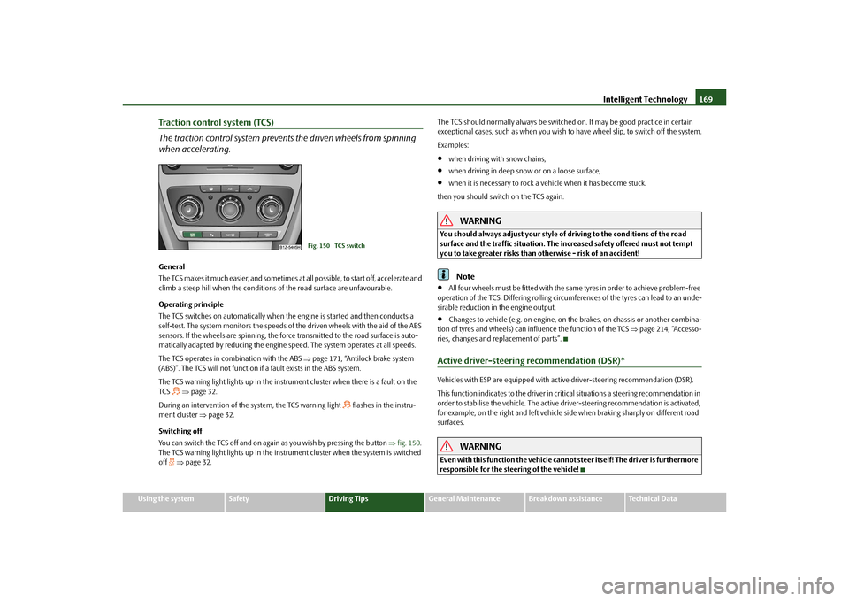
You can switch the TCS off and on again as you wish by pressing the button fig. 150 .
The TCS warning light lights up in the instru ment cluster when the system is switched
off
page 32. The TCS should normally always
be switched on. It may be good practice in certain
exceptional cases, such as when you wish to have wheel slip, to switch off the system.
Examples:
when driving with snow chains,
when driving in deep snow or on a loose surface,
when it is necessary to rock a vehicle when it has become stuck.
then you should switch on the TCS again.
WARNING
You should always adjust your style of driving to the conditions of the road
surface and the traffic situation. The increased safety offered must not tempt
you to take greater risks than otherwise - risk of an accident!
Note
All four wheels must be fitted with the same tyres in order to achieve problem-free
operation of the TCS. Differing rolling circumferences of the tyres can lead to an unde-
sirable reduction in the engine output.
Changes to vehicle (e.g. on engine, on the brakes, on chassis or another combina-
tion of tyres and wheels) can influence the function of the TCS page 214, “Accesso-
ries, changes and replacement of parts”.
Active driver-steering recommendation (DSR)*Vehicles with ESP are equipped with active driver-steering recommendation (DSR).
This function indicates to the driver in crit ical situations a steering recommendation in
order to stabilise the vehicle. The active driver-steering recommendation is activated,
for example, on the right and left vehicle si de when braking sharply on different road
surfaces.
WARNING
Even with this function the vehicle cann ot steer itself! The driver is furthermore
responsible for the steering of the vehicle!
Fig. 150 TCS switch
s43s.1.book Page 169 Thursday, May 13, 2010 1:21 PM
Page 172 of 275
Intelligent Technology171
Using the system
Safety
Driving Tips
General Maintenance
Breakdown assistance
Technical Data
Brake boosterThe brake booster boosts the pressure which you generate with the brake pedal. The
necessary pressure is only genera ted when the engine is running.
WARNING
Never switch off the engine before the vehicle is stationary.
The brake booster only operates when the engine is running. Greater phys-
ical effort for braking is required when en gine is switched off. Because if you do
not stop as normal, this can cause an accident and severe injuries.
Antilock brake system (ABS)ABS prevents the wheels locking when braking.General
The ABS contributes significantly to enhanc ing the active safety of your vehicle.
Compared to a vehicle not fitted with the ABS brake system, you are able to retain
optimal steering ability even during a full br ake application on a slippery road surface
because the wheels do not lock up.
You must not expect, however, that the br aking distance will be shorter under all
circumstances as a result of the ABS. The braking distance for example on gravel and
fresh snow, when you should anyway be driving slowly and cautiously, will be longer.
Operating principle
The brake pressure will be reduced on a wheel which is rotating at a speed which is too
low for the speed of the vehicle and tending to lock. This control cycle is noticeable
from a pulsating movement of the brake pedal which is accompanied by noises.
This is consciously intended to provide the driver with the information that the wheels
are tending to lock (ABS control range) . You must always keep the brake pedal
depressed to enable the ABS to optimally control the brake application in this braking
range. Never interrupt the application of the brakes!
WARNING
The ABS can also not overcome the physical limits of your vehicle. Please do
not forget this, particularly when driving on icy or wet road surfaces. If the ABS
is operating within the control range, adapt your speed immediately to the
conditions of the road surface and the traffic situation. The increased safety
offered by the ABS must not tempt you to take greater risks than otherwise -
risk of an accident!
The normal braking system is still fully functional if there is an ABS fault.
Visit a specialist garage as quickly as poss ible and adjust your style of driving to
take account of the ABS fault in the meantime since you will not know the extent
of the fault and in how far the braking efficiency is affected.Note
A warning light comes on if a fault occurs in the ABS system
page 33.
Changes to vehicle (e.g. on engine, on the brakes, on chassis or another combina-
tion of tyres and wheels) can in fluence the function of the ABS page 214, “Accesso-
ries, changes and replacement of parts”.
Brake Assist*During a severe brake application (e.g. if a hazard exists), the Brake Assist increases the
braking force and thus makes it possible to rapidly produce the pressure required in
the brake system.
The majority of drivers do a pply the brakes in good time in dangerous situations, but
do not depress the brake pedal with sufficient pressure. Consequently, it is not possible
for the vehicle to achieve its maximum deceleration and the vehicle covers a greater
distance than necessary.
The Brake Assist is activated by the very qu ick operation of the brake pedal. In such
cases, a much greater braking pressure exists than during a normal brake application.
This makes it possible, even with a relatively low resistance of the brake pedal, to
produce an adequate pressure in the brake system in the shortest possible time, which
is required for maximum dece leration of the vehicle. You must apply the brake pedal
firmly and hold it in this position in or der to achieve the shortest possible braking
distance.
s43s.1.book Page 171 Thursday, May 13, 2010 1:21 PM
Page 174 of 275
Intelligent Technology173
Using the system
Safety
Driving Tips
General Maintenance
Breakdown assistance
Technical Data
one wheel per axle was changed.
Basic setting of the system
After changing the tyre inflation pressures, after changing one or several wheels, the
position of a wheel on the vehicle (e.g. exch anging the wheels between the axles) or
when the warning light lights up while drivin g, a basic setting of the system must be
carried out as follows.
Inflate all tyres to the specified inflation pressure page 208.
Switch on the ignition.
Press button page 172, fig. 151 for more than 2 seconds. While pressing
the button, the warning light
lights up. At the same time the memory of the system
is erased and the new calibration is started, which is confirmed with an audible signal
and then the warning light
goes out.
If the warning light
does not go out after the basic setting, there is a fault in the
system. Have the vehicle inspected by your nearest specialist garage.
Warning light
lights up
If the tyre inflation pressure of at least one wheel is insufficiently inflated in comparison
to the stored basic value, the warning light
lights up.
Warning light
flashes
If the warning light flashes, there is a system fault. Have the vehicle inspected by your
nearest specialist garage.
WARNING
When the warning light
lights up, immediately reduce the speed and
avoid sudden steering and brake manoeuvr es. Please stop the vehicle without
delay at the nearest possible stop and in spect the tyres and their inflation pres-
sures.
The driver is responsible for the correct tyre inflation pressures. For this
reason, the tyre inflation pressu res must be checked regularly.
Under certain circumstances (e.g. sporty style of driving, wintry or unpaved
roads) the warning light
can be delayed or does not light up at all.
The tyre pressure monitoring system does not take away the responsibility
from the driver for the correct tyre inflation pressure.
Note
The tyre pressure monitoring system:
does not replace the regular tyre inflatio n pressure control, because the system
cannot detect an even pressure loss,
cannot warn in case of very rapid tyre inflation pressure loss, e.g. in case of sudden
tyre damage. In this case ca refully bring the vehicle to a standstill without sudden
steering movements and without sharp braking.
In order to ensure a proper functioning of the tyre inflation pressure-control
system, it is necessary to carry out the ba sic setting again every 10 000 km or 1x a
year.
Diesel particle filter* (diesel engine)In the diesel particle filter the resu lting soot particles are collected and
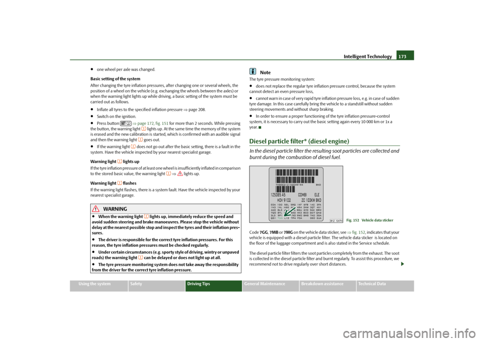
burnt during the combustion of diesel fuel.Code 7GG, 7MB or 7MG on the vehicle data sticker, see fig. 152 , indicates that your
vehicle is equipped with a diesel particle fi lter. The vehicle data sticker is located on
the floor of the luggage compartment and is also stated in the Service schedule.
The diesel particle filter filters the soot particles completely from the exhaust. The soot
is collected in the diesel particle filter and burnt regularly. To assist this procedure, we
recommend not to drive regu larly over short distances.
Fig. 152 Vehicle data sticker
s43s.1.book Page 173 Thursday, May 13, 2010 1:21 PM
Page 176 of 275
Driving and the Environment175
Using the system
Safety
Driving Tips
General Maintenance
Breakdown assistance
Technical Data
Driving and the EnvironmentThe first 1 500 kilometres and then afterwardsA new engine
The engine has to be run in during the first 1 500 kilometres.Up to 1 000 kilometres– Do not drive faster than 3/4 of the maximum speed of the gear in use, that is 3/4 of
the maximum permissi ble engine speed.
– Do not use full throttle.
– Avoid high engine revolutions.
– Do not tow a trailer.From 1 000 up to 1 500 kilometres– Increase the power output of the engine gradually up to the full speed of the gear
engaged, that is up to the maxi mum permissible engine revolutions.
During the first operating hours the engine ha s higher internal friction than later until
all of the moving parts have harmonized. Th e driving style which you adopt during the
first approx.1 500 kilometres plays a decisive part in the success of running in your
vehicle.
You should not drive at unnecessarily high engine revolutions even after the
running-in period is complete . The maximum permissible en gine speed is marked by
the beginning of the red zone on the scale of the revolutions counter. Shift up into the
next higher gear on a vehi cle fitted with manual gear box before the red zone is
reached. Extremely high engine revolutions are automatically governed, by the way.
For a vehicle fitted with a manual gearbox the converse situation also applies: Do not
drive at engine revolutions which are too low. Shift down as soon as the engine is no
longer running smoothly.
Caution
All the speed and engine revolution figures ap ply only when the engine is at its normal
operating temperature. Never rev up an engine which is cold, neither when the vehicle
is stationary nor when driving in individual gears.
For the sake of the environment
Not driving at unnecessari ly high engine revolutions and shifting to a higher gear as
early as possible are ways to minimise fu el consumption and operating noise levels
and protects the environment.New tyresNew tyres have to be “run in” since they do not offer optimal grip at first. You should
take account of this fact for the first 500 kilometres and drive particularly carefully.New brake padsAllow for the fact that new brake pads do no t achieve their full braking efficiency until
approximately 200 kilometres. New brake pads must be first “run in” before they
develop their optimal friction force. You ca n, however, compensate for this slightly
reduced braking force by increasing the pressure on the brake pedal.
This guideline also applies to any new brake pads installed at a future date.
During the running-in pe riod, you should avoid excessive stresses on the brakes. This
includes, for example, violent braking, part icularly from very high speeds, and also
when crossing mountain passes.
s43s.1.book Page 175 Thursday, May 13, 2010 1:21 PM
Page 178 of 275

Driving and the Environment177
Using the system
Safety
Driving Tips
General Maintenance
Breakdown assistance
Technical Data
guidelines given in this chapter in order to
make best use of these characteristics and
to maintain their effectiveness.
The optimal engine speed should be obtained when accelerating, in order to avoid a
high fuel consumption and resonance of the vehicle.
Looking ahead when driving
A vehicle's highest fuel consumption occurs it accelerates.Avoid accelerating and braking unnecessarily. If you drive with forsight you will not
need to brake so often and will also then not have to accelerate so much. Let your
vehicle coast to a stop, for example, if this is possible, when you see that the next set of
traffic lights is at red.Shifting gears and saving energy
Shifting up early saves on fuel.Manual gearbox– Drive no more than about one length of your vehicle in first gear.
– Always shift up into the next higher gear at approx. 2 000 to 2 500 revs.Automatic gearbox– Depress the accelerator pedal slowly. Do not depress it beyond the kickdown
position, however. An effective way of achieving good fuel economy is to shift up
early. You will consume
more fuel if you drive at unnecessaril y high revolutions in any given gear.
The fig. 153 shows the ratio of fuel consumption to the speed of your vehicle in the
relevant gears. Fuel consumptio n in 1st gear is the highest, while that in 5th or 6th gear
is the lowest.
Only depress the accelerator pedal slowly if your vehicle is fitted with an automatic
gearbox in order to automatically select an economic driving programme. You will
achieve good fuel economy by shifting up early and shifting down late.
Note
Also use the information supplied by the multi-functional indicator* page 19.Avoiding full throttle
Driving more slowly means saving fuel.Sensitive use of the accelerator will not only significantly reduce fuel consumption but
also positively influence environmenta l pollution and wear of your vehicle.
You should avoid exploiting the top speed of your vehicle wherever possible. Fuel
consumption, pollutant emissions and vehicl e noises increase disproportionally at
high speeds.
The fig. 154 shows the ratio of fuel consumption to the speed of your vehicle. You
will cut your fuel consumption by half if you only make use three-quarters of the
possible top speed of your vehicle.
Fig. 153 Fuel consumption in litres/100
km. and speed in km/h.
Fig. 154 Fuel consumption in litres/100
km. and speed in km/h.
s43s.1.book Page 177 Thursday, May 13, 2010 1:21 PM
Page 180 of 275
Driving and the Environment179
Using the system
Safety
Driving Tips
General Maintenance
Breakdown assistance
Technical Data
Checking tyre inflation pressures
Tyres which are correctly inflated save fuel.Always ensure that your tyres are inflated to the correct pressure at all times. The rolling
resistance will be increased if the tyre filling pressure is too low. This will not only
increase fuel consumption but also tyre we ar and the driving behaviour will worsen.
Always check the inflation pr essure of the tyres when cold.
Do not drive with winter tyres all year round for this costs about 10 % more fuel.
Winter tyres are also louder.No unnecessary ballast
Transporting ballast costs fuel.The fact that every kilogram of extra weight increases your fuel consumption means
that it is worth taking a look in the luggage compartment to avoid transporting any
unnecessary ballast.
It is particularly in town traffic, when one is accelerating quite often, that the vehicle
weight will have a significant effect upon the fuel consumption. A rule of thumb here
is that an increase in weight of 100 kilograms will cause an increase in fuel consump-
tion of about 1 litre/100 kilometres.
You may frequently also leave a roof rack fitted on just out of convenience, although
you no longer need it. The increased aerodyna mic drag of your vehicle causes it to use
about 10% more fuel than normal at a speed of 100 - 120 km/h, even when you are not
carrying a load on the roof.Saving electricity
Generating electricity costs fuel.– Switch off electrical components as soon as you no longer need them.
When the engine is running, the alternator generates and supplies electrical power.
The greater the load on the alternator as a result of having a large number of electrical
components switched on, the more fuel will be consumed for operating the
alternator.
Keeping a log of your fuel consumptionIf you really wish to keep a close check on your fuel consumption, it is best to enter
the figures in a logbook. This does not take much time but is a very worthwhile exer-
cise. It enables you to detect any change (p ositive and negative) at an early stage and
to take any appropriate action.
If you find that your fuel consumption is too high, you should reflect on how, where
and in what conditions you have driven the vehicle since you last refuelled.Environmental compatibilityEnvironmental protection has played a major role in the design, selection of materials
and manufacture of your new Škoda. Particular emphasis has been paid to a number
of aspects, including:
Design measures
Joints designed to be easily detached.
Simplified disassembly due to the modular structure system.
Improved purity of differ ent classes of materials.
Identification of all plastic parts in accordance with VDA Recommendation°260.
Reduced fuel consumption and exhaust emission CO
2.
Minimum fuel leakage during accidents.
Reduced noise.
Choice of materials
Extensive use of re cyclable material.
Air conditioning filled with CFC-free refrigerant.
No cadmium.
No asbestos.
Reduction in the “vaporisation” of plastics.
Manufacture
Solvent-free cavity protection.
s43s.1.book Page 179 Thursday, May 13, 2010 1:21 PM