warning lights SKODA OCTAVIA 2011 2.G / (1Z) Workshop Manual
[x] Cancel search | Manufacturer: SKODA, Model Year: 2011, Model line: OCTAVIA, Model: SKODA OCTAVIA 2011 2.G / (1Z)Pages: 248, PDF Size: 3.79 MB
Page 108 of 248
The function is automatically activated each time the ignition is switched on.
In the start-stop mode, the engine automatically switches to the vehicle's idle
phase, e.g. when stopped at traffic lights.
Information regarding the current state of the
“START-STOP” system is indicated
in the display of the instrument cluster.
Automatic engine shut down (stop phase)
– Stop the vehicle (where necessary, apply the handbrake).
– Take the vehicle out of gear.
– Take your foot off the clutch.
Automatic engine restart (start phase).
– Push down on the clutch.
Switching the
“START-STOP” system on and off
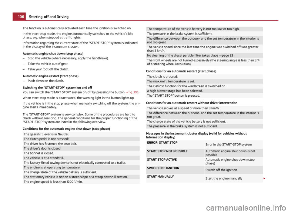
You can switch the “START STOP” system on/off by pressing the button ⇒ fig. 105.
When start-stop mode is deactivated, the warning light in the button lights up.
If the vehicle is in the stop phase when manually switching off the system, the en-
gine starts immediately.
The “START-STOP” system is very complex. Some of the procedures are hard to
check without servicing. The general conditions for the proper functioning of the
“START-STOP” system are listed in the following overview.
Conditions for the automatic engine shut down (stop phase) The gearshift lever is in Neutral.
The clutch pedal is not pressed!
The driver has fastened the seat belt.
The driver's door is closed.
The bonnet is closed.
The vehicle is at a standstill.
The factory-fitted towing device is not electrically connected to a trailer.
The engine is at operating temperature.
The charge state of the vehicle battery is sufficient.
The stationary vehicle is not on a steep slope or a steep downhill section.
The engine speed is less than 1200 1/min. The temperature of the vehicle battery is not too low or too high.
The pressure in the brake system is sufficient.
The difference between the outdoor- and the set temperature in the interior is
not too great.
The vehicle speed since the last time the engine was switched off was greater
than 3 km/h.
No cleaning of the diesel particle filter takes place
⇒ page 23 The front wheels are not turned excessively (the steering angle is less than 3/4
of a steering wheel revolution). Conditions for an automatic restart (start phase)
The clutch is pressed.
The max./min. temperature is set.
The Defrost function for the windscreen is switched on.
A high blower stage has been selected.
The “START STOP” button is pressed.
Conditions for an automatic restart without driver intervention
The vehicle moves at a speed of more than 3 km/h.
The difference between the outdoor- and the set temperature in the interior is
too great.
The charge state of the vehicle battery is not sufficient.
The pressure in the brake system is not sufficient.
Messages in the instrument cluster display (valid for vehicles without
Information display) ERROR: START STOP
Error in the START-STOP system
START STOP NOT POSSIBLE Automatic engine shut down is not
possible
START STOP ACTIVE Automatic engine shut down (stop
phase)
SWITCH OFF IGNITION
Switch off the ignition
START MANUALLY
Start the engine manually
£106
Starting-off and Driving
Page 112 of 248

Selector lever positions
Fig. 106 Selector lever/information display: Selector lever positions
The current selector lever position is indicated in the information display of the in-
strument cluster ⇒ fig. 106 - right. In the positions D and S the gear you have al-
ready engaged will be additionally displayed on the display.
P - Parklock
The driven wheels are locked mechanically in this position.
The Parklock must only be engaged when the vehicle is stationary ⇒ .
If you wish to move the selector lever into or out of this position, you must press
the Shiftlock button in the handle of the selector lever and at the same time de-
press the brake pedal.
If the battery is used, the selector lever cannot be moved out of the position P.
R - Reverse gear
Reverse gear must only be engaged when the vehicle is stationary and the engine
idling ⇒ .
The brake pedal must be depressed and at the same time the Shiftlock must be
pressed, if you wish to obtain the selector lever positions R, P or N.
When the ignition is switched on and the selector lever is in position R, the re-
verse lights will come on.
N - Neutral
The transmission is in Neutral in this position. The brake pedal must be depressed (if the lever is in its position for longer than 2
seconds) in order to move the selector lever out of the position
N into the position
D or R, with the ignition switched on, on a vehicle travelling at less than 5 km/
hour or on a stationary vehicle.
D - Position for driving forward
When the selector lever is in this position, the forward gears are shifted up and
down automatically in line with engine load, vehicle speed and the dynamic shift
programme.
You must depress the brake pedal if you wish to move into position D from N
when the vehicle is travelling at less than 5
km/hour or is stationary ⇒ .
Under certain circumstances (e.g. when driving in mountainous regions or when
towing a trailer) it may be beneficial to select the manual shift programme
⇒ page 112 for a short time in order to adapt the gearbox ratios manually to the
driving situations.
S - Position for sporty style of driving
Shifting up later into a higher gear makes it possible to fully exploit the power po-
tential of the engine. The gearbox also then shifts down at higher engine speeds
as in the position D .
The gearbox does not shift into the 6th gear in the position S, because the maxi-
mum speed is reached with the 5th gear 1)
.
The Shiftlock on the selector lever grip must be pressed when moving the selec-
tor lever out of the position D into the position S. WARNING
● Never move the selector lever into position
R or P when driving - risk of an
accident!
● When the engine is running and the vehicle is stationary, it is necessary to
hold the car with the brake pedal in all the positions of the selector lever (ex-
cept P and N) since the power transmission is never completely interrupted,
also not when the engine is idling - the vehicle creeps. £1)
Not valid for vehicles with automatic gearbox DSG. 110
Automatic gearbox
Page 113 of 248

WARNING (Continued)
● You must on no account unintentionally operate the throttle (e.g. by hand
from the engine compartment) if a drive position is engaged when the car is
stationary. The vehicle would otherwise immediately start off - also when the
handbrake is firmly applied - risk of an accident!
● You must move the selector lever into position P and firmly apply the
handbrake first before you or any other person opens the bonnet and starts
working on the engine when it is running - risk of accident! It is also essential
to observe all warnings ⇒ page 181, Working in the engine compartment
.
Selector lever lock Automatic selector lever lock
With the ignition on, the selector lever is locked when it is in the positions P and
N. You must first of all depress the brake pedal in order to move the selector lever
out of this position. The warning light ⇒
page 27 lights up in the instrument
cluster as a reminder for the driver when the selector lever is in the positions P
and N.
A time delay element ensures that the selector lever is not blocked when rapidly
switching over the position N (e.g. from R to D). This does, for example, allow one
to seesaw out a stuck vehicle. The selector lever lock will click into place if the lev-
er is in the N position for more than 2 seconds without the brake pedal being
pressed.
The selector lever lock is only active if the vehicle is stationary or moving at speed
of less than 5 km/hour. The lock is switched off automatically into position N
when the car is travelling at a higher speed.
Shiftlock button
The Shiftlock button in the handle of selector lever prevents certain selector lever
positions being engaged inadvertently. The selector lever lock is cancelled when
you press the Shiftlock button.
Keylock - Ignition key withdrawal lock
You can only withdraw the ignition key after switching off the ignition if the selec-
tor lever is in position P. If the ignition key is withdrawn, the selector lever is
blocked in position P . Kickdown function The kickdown function provides you with maximum acceleration
power.
Fully depressing the accelerator pedal allows the kickdown function to be activa-
ted in the desired driving program. This function has precedence over the driving
programme and serves for maximum acceleration of the vehicle when exploiting
the maximum power potential of the engine without taking into account the cur-
rent selector lever position ( D, S or Tiptronic ). The gearbox shifts down to one or
several gears in line with the driving state and the vehicle accelerates. The gear-
box does not shift up into the highest gear until the engine has reached its maxi-
mum revolutions for this gear range. WARNING
Please note that using the kickdown function can result in the driven wheels
spinning on a smooth or slippery road surface - risk of skidding!
Dynamic shift programme The automatic gearbox of your vehicle is controlled electronically. Shifting up and
down through the gears is performed automatically on the basis of pre-defined
driving programmes.
Adopting a moderate style of driving
will cause the gearbox to select the most
economical driving programme. Shifting up into a higher gear as soon as possible
and shifting down as late as possible will have a favourable effect on your fuel
consumption.
Adopting a sporty style of driving with rapid movements of the accelerator pedal
combined with sharp acceleration and frequent changes in speed, exploiting the
top speed of the car or depressing the accelerator pedal (kickdown function), will
cause the gearbox to switch over to this style of driving and shift down earlier
with frequent changes in gears in comparison to the moderate style of driving.
Selecting the most appropriate driving programme for the particular style of driv-
ing is a continuous process. Irrespective of this it is, however, possible to switch or
shift down into a dynamic shift programme by depressing the accelerator rapidly.
The gearbox shifts down into a lower gear matching the speed of the car and this
allows you to accelerate rapidly (e.g. when overtaking) without having to depress £ 111
Automatic gearbox Using the system Safety Driving Tips General Maintenance Breakdown assistance Technical data
Page 148 of 248

If the airbag was switched off using diagnostic equipment:
●
The warning light for the airbag system lights up for 4 seconds after switching
on the ignition and then flashes for 12 seconds afterwards in 2 second intervals.
The following situation applies if the airbag has been switched off using the
switch for the airbag in the storage compartment:
● the airbag indicator light in the instrument cluster comes on for about 4 sec-
onds each time the ignition is switched on,
● if the airbags are switched off, this is indicated in the middle of the dash panel
by the lighting up of the indicator light
⇒ fig. 129 - right. Note
Your authorised ŠKODA Service Partner will be able to advise you whether nation-
al legislation in your country allows airbags in your vehicle to be deactivated, and
which ones.
Switch for the front passenger airbag Fig. 129 Storage compartment: Switch for the front passenger airbag/indicator light for a
switched off front seat passenger airbag
Only the front passenger airbag is deactivated with the switch.
Deactivating an airbag
– Switch off the ignition.
– Turn the slot of the airbag switch using the key in the position 2 (
OFF)
⇒ fig. 129 .
– Check whether the indicator light
in the middle of the dash panel
lights up when the ignition is switched on ⇒ fig. 129 - right. Switching on an airbag
–
Switch off the ignition.
– Turn the slot of the airbag switch using the key in the position 1 (
ON)
⇒ fig. 129 .
– Check whether the airbag indicator light
in the middle of the dash
panel lights up when the ignition is switched on ⇒ fig. 129 - right.
The airbag should only be switched off under exceptional circumstances
⇒ page 145.
Indicator light (airbag switched off)
The airbag indicator light is located in the middle of the dash panel ⇒ fig. 129 -
right.
If the front passenger airbag is switched off, the warning light comes on about 4
seconds after the ignition is switched on.
There is a system fault present in the airbag switch off ⇒ if the indicator light
flashes. Please have the car inspected immediately by a specialist garage. WARNING
● The driver is responsible for whether the airbag is switched on or switched
off.
● Only switch off the airbag when the ignition is switched off! Otherwise a
fault can occur in the system for the airbag deactivation.
● If the warning light
(airbag switched off) flashes:
– Front passenger airbag is not deployed in the event of an accident!
– It is also important to have the system inspected without delay by a
specialist garage. 146
Airbag system
Page 156 of 248
Driving Tips
Intelligent Technology General information WARNING
Lack of fuel can cause irregular engine running or lead to shut down the en-
gine. Consequently, the systems described in this chapter may to lose their ef-
fectiveness, resulting in loss of vehicle control – risk of accident!
Electronic stability programme (ESP)
General Fig. 138 ESP system: Switch for TCS
The ESP aids you in maintaining control of your vehicle in situations in which the
vehicle is driving at its dynamic limits, such as entering a curve fast. The risk of
skidding is reduced and your car thus offers greater driving stability depending on
the conditions of the road surface. The system operates at all speeds.
The following systems are integrated into the electronic stability programme:
● Electronic Differential Lock (EDL),
● Traction control system (TCS),
● active driver-steering recommendation (DSR),
● Antilock brake system (ABS), ●
Brake Assist,
● Uphill Start Assist.
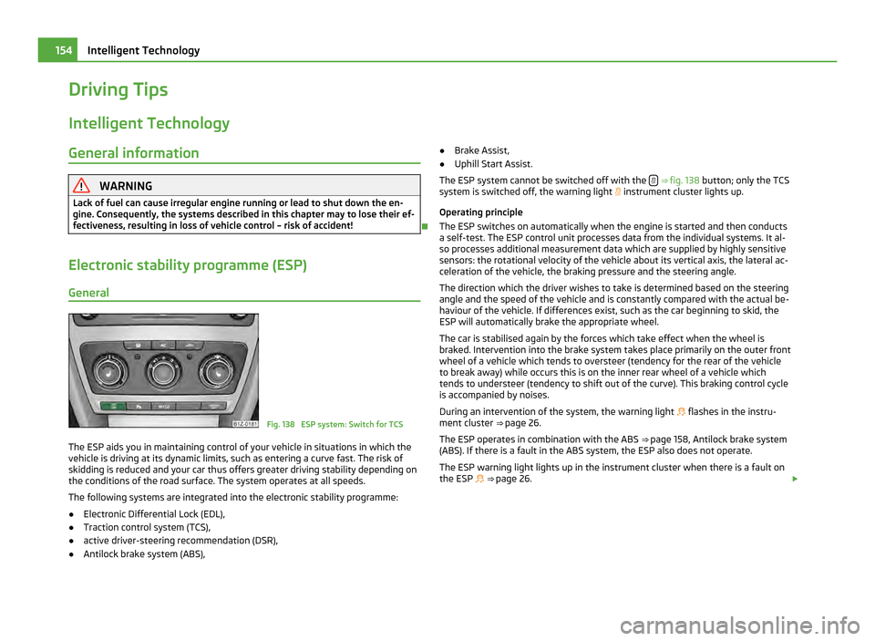
The ESP system cannot be switched off with the ⇒
fig. 138 button; only the TCS
system is switched off, the warning light instrument cluster lights up.
Operating principle
The ESP switches on automatically when the engine is started and then conducts
a self-test. The ESP control unit processes data from the individual systems. It al-
so processes additional measurement data which are supplied by highly sensitive
sensors: the rotational velocity of the vehicle about its vertical axis, the lateral ac-
celeration of the vehicle, the braking pressure and the steering angle.
The direction which the driver wishes to take is determined based on the steering
angle and the speed of the vehicle and is constantly compared with the actual be-
haviour of the vehicle. If differences exist, such as the car beginning to skid, the
ESP will automatically brake the appropriate wheel.
The car is stabilised again by the forces which take effect when the wheel is
braked. Intervention into the brake system takes place primarily on the outer front
wheel of a vehicle which tends to oversteer (tendency for the rear of the vehicle
to break away) while occurs this is on the inner rear wheel of a vehicle which
tends to understeer (tendency to shift out of the curve). This braking control cycle
is accompanied by noises.
During an intervention of the system, the warning light flashes in the instru-
ment cluster ⇒ page 26.
The ESP operates in combination with the ABS ⇒ page 158, Antilock brake system
(ABS). If there is a fault in the ABS system, the ESP also does not operate.
The ESP warning light lights up in the instrument cluster when there is a fault on
the ESP ⇒ page 26. £154
Intelligent Technology
Page 158 of 248

Traction control system (TCS)
The traction control system prevents the driven wheels from spin-
ning when accelerating.
Fig. 139 TCS switch
General
The TCS makes it much easier, and sometimes at all possible, to start off, acceler-
ate and climb a steep hill when the conditions of the road surface are unfavoura-
ble.
Operating principle
The TCS switches on automatically when the engine is started and then conducts
a self-test. The system monitors the speeds of the driven wheels with the aid of
the ABS sensors. If the wheels are spinning, the force transmitted to the road sur-
face is automatically adapted by reducing the engine speed. The system operates
at all speeds.
The TCS operates in combination with the ABS ⇒ page 158, Antilock brake system
(ABS)
. The TCS will not function if a fault exists in the ABS system.
The TCS warning light lights up in the instrument cluster when there is a fault on
the TCS
⇒ page 26.
During an intervention of the system, the TCS warning light flashes in the in-
strument cluster ⇒ page 26.
Switching off
You can also switch off the TCS system by pressing the ⇒ fig. 139 button, or, in ve-
hicles with ESP, by pressing the ⇒ fig. 138 button. The TCS warning light lights up
in the instrument cluster when the TCS is switched off . The TCS should normally always be switched on. It may be good practice in certain
exceptional cases, such as when you wish to have wheel slip, to switch off the
system.
Examples:
● when driving with snow chains,
● when driving in deep snow or on a loose surface,
● when it is necessary to rock a car free when it has become stuck.
then you should switch on the TCS again. WARNING
You should always adjust your style of driving to the conditions of the road
surface and the traffic situation. The increased safety offered must not tempt
you to take greater risks than otherwise - risk of an accident! Note
● All four wheels must be fitted with the same tyres in order to achieve prob-
lem-free operation of the TCS. Differing rolling circumferences of the tyres can
lead to an undesirable reduction in the engine output.
● Changes to vehicle (e.g. on engine, on the brakes, on chassis or another combi-
nation of tyres and wheels) can influence the function of the TCS ⇒
page 197, Ac-
cessories, changes and replacement of parts.
Active driver-steering recommendation (DSR) This function indicates to the driver in critical situations a steering recommenda-
tion in order to stabilise the vehicle. The active driver-steering recommendation is
activated, for example, on the right and left vehicle side when braking sharply on
different road surfaces. WARNING
Even with this function the vehicle cannot steer itself! The driver is further-
more responsible for the steering of the vehicle! 156
Intelligent Technology
Page 161 of 248
The Brake Assist is able to help you achieve a shorter braking distance in emer-
gency situations by rapidly producing the pressure required in the brake system. It
fully exploits the attributes of the ABS. After you release the brake pedal, the
function of the Brake Assist is automatically switched off and the brakes operate
in the normal way.
The Brake Assist is part of the ESP system. If a fault occurs in the ESP, the Brake
Assist function is also not available. Further information on the ESP
⇒ page 154.WARNING
● The Brake Assist is also not able to overcome the physical limits of your car
in terms of the braking distance required.
● Adapt your speed to the conditions of the road surface and to the traffic
situation.
● The increased safety offered by the Brake Assist must not tempt you to
take a greater safety risk than otherwise.
Uphill Start Assist The uphill start assist makes it easier to start off on steep hills. The system assists
a start off by holding the brake pressure produced by the brake pedal actuation
for approx. 2 seconds after releasing the brake pedal. The driver can therefore
move his foot from the brake pedal to the accelerator pedal and start off on the
slope, without having to actuate the handbrake. The brake pressure drops gradu-
ally the more you operate the accelerator pedal. If the vehicle does not start off
within 2 seconds, it starts to roll back.
The uphill start assist is active as of a 5 % slope, if the driver door is closed. It is
always active on slopes when in forward or reverse start off. When driving down-
hill, it is inactive.
Electromechanical power steering The power steering enables you to steer the vehicle with less physical force.
With the electromechanical power steering, the steering assist is automatically
adapted to the speed and to the steering angle.
It is still possible to fully steer the vehicle if the power steering fails or if the en-
gine is not running (vehicle being towed in). The only difference is that greater
physical effort is required. If there is a fault in the power steering, the warning light
or lights up in the
instrument cluster ⇒
page 24. WARNING
Contact your specialist garage if the power steering is defective.
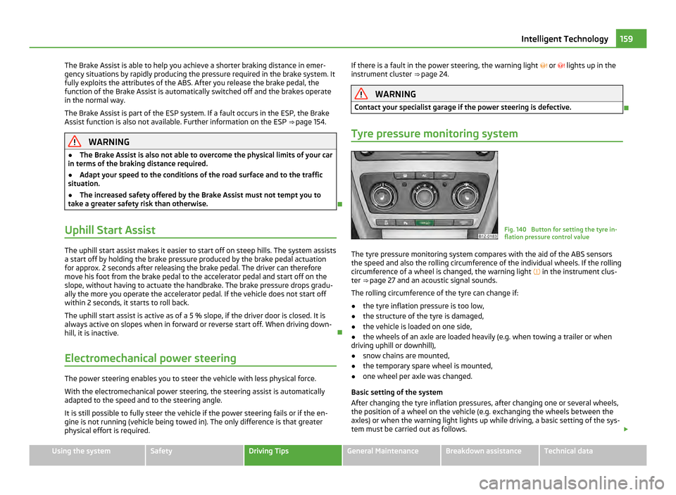
Tyre pressure monitoring system Fig. 140 Button for setting the tyre in-
flation pressure control value
The tyre pressure monitoring system compares with the aid of the ABS sensors
the speed and also the rolling circumference of the individual wheels. If the rolling
circumference of a wheel is changed, the warning light
in the instrument clus-
ter ⇒ page 27 and an acoustic signal sounds.
The rolling circumference of the tyre can change if:
● the tyre inflation pressure is too low,
● the structure of the tyre is damaged,
● the vehicle is loaded on one side,
● the wheels of an axle are loaded heavily (e.g. when towing a trailer or when
driving uphill or downhill),
● snow chains are mounted,
● the temporary spare wheel is mounted,
● one wheel per axle was changed.
Basic setting of the system
After changing the tyre inflation pressures, after changing one or several wheels,
the position of a wheel on the vehicle (e.g. exchanging the wheels between the
axles) or when the warning light lights up while driving, a basic setting of the sys-
tem must be carried out as follows. £ 159
Intelligent Technology Using the system Safety Driving Tips General Maintenance Breakdown assistance Technical data
Page 162 of 248
●
Inflate all tyres to the specified inflation pressure ⇒ page 192.
● Switch on the ignition.
● Press button
⇒ fig. 140
for more than 2
seconds. While pressing the but-
ton, the warning light lights up. At the same time the memory of the system is
erased and the new calibration is started, which is confirmed with an audible sig-
nal and then the warning light goes out.
● If the warning light does not go out after the basic setting, there is a fault in
the system. Have the vehicle inspected by your nearest specialist garage.
Warning light lights up
If the tyre inflation pressure of at least one wheel is insufficiently inflated in com-
parison to the stored basic value, the warning light ⇒ lights up.
Warning light flashes
If the warning light flashes, there is a system fault. Have the vehicle inspected by
your nearest specialist garage. WARNING
● When the warning light lights up, immediately reduce the speed and
avoid sudden steering and brake manoeuvres. Please stop the vehicle without
delay at the nearest possible stop and inspect the tyres and their inflation
pressures.
● The driver is responsible for the correct tyre inflation pressures. For this
reason, the tyre inflation pressures must be checked regularly.
● Under certain circumstances (e.g. sporty style of driving, wintry or unpaved
roads) the warning light can be delayed or does not light up at all.
● The tyre pressure monitoring system does not take away the responsibility
from the driver for the correct tyre inflation pressure. Note
The tyre pressure monitoring system:
● does not replace the regular tyre inflation pressure control, because the sys-
tem cannot detect an even pressure loss,
● cannot warn in case of very rapid tyre inflation pressure loss, e.g. in case of
sudden tyre damage. In this case carefully bring the vehicle to a standstill without
sudden steering movements and without sharp braking.
● In order to ensure a proper functioning of the tyre inflation pressure-control
system, it is necessary to carry out the basic setting again every 10 000 km or 1x a
year. Diesel particle filter (diesel engine) In the diesel particle filter the resulting soot particles are collected
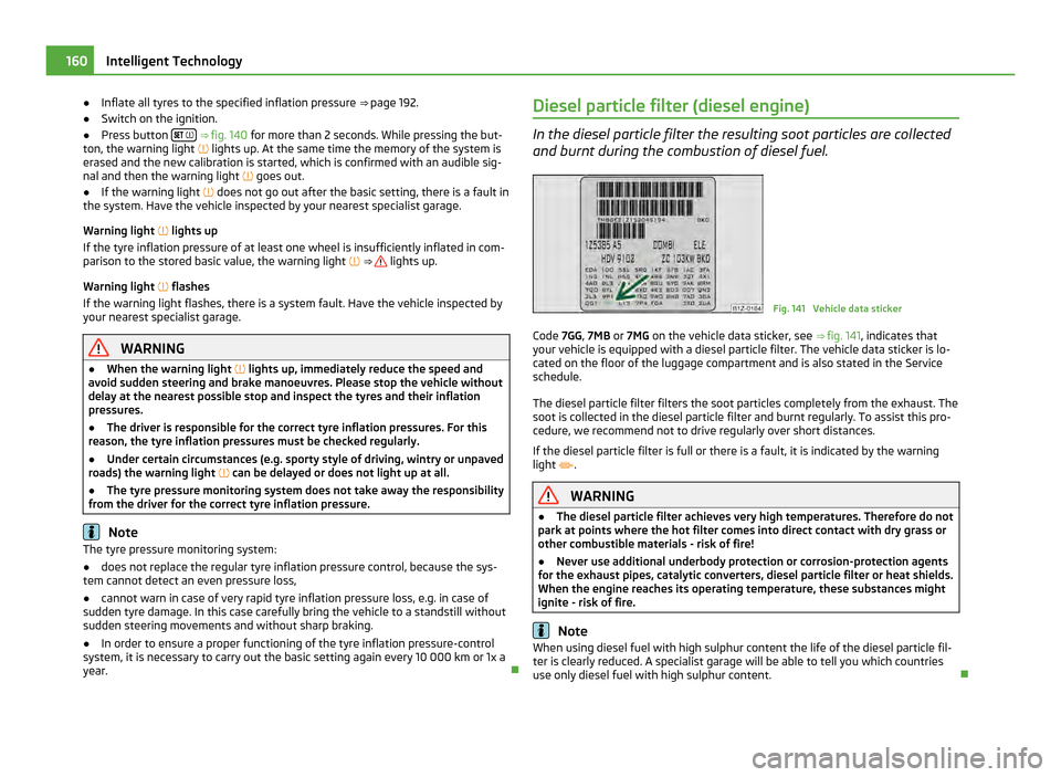
and burnt during the combustion of diesel fuel. Fig. 141 Vehicle data sticker
Code 7GG , 7MB or 7MG on the vehicle data sticker, see ⇒ fig. 141 , indicates that
your vehicle is equipped with a diesel particle filter. The vehicle data sticker is lo-
cated on the floor of the luggage compartment and is also stated in the Service
schedule.
The diesel particle filter filters the soot particles completely from the exhaust. The
soot is collected in the diesel particle filter and burnt regularly. To assist this pro-
cedure, we recommend not to drive regularly over short distances.
If the diesel particle filter is full or there is a fault, it is indicated by the warning
light
. WARNING
● The diesel particle filter achieves very high temperatures. Therefore do not
park at points where the hot filter comes into direct contact with dry grass or
other combustible materials - risk of fire!
● Never use additional underbody protection or corrosion-protection agents
for the exhaust pipes, catalytic converters, diesel particle filter or heat shields.
When the engine reaches its operating temperature, these substances might
ignite - risk of fire. Note
When using diesel fuel with high sulphur content the life of the diesel particle fil-
ter is clearly reduced. A specialist garage will be able to tell you which countries
use only diesel fuel with high sulphur content. 160
Intelligent Technology
Page 164 of 248

–
For vehicles with petrol engine only refuel with unleaded petrol ⇒ page 176,
Unleaded petrol.
– Never run the fuel tank completely empty.
– Do not switch off the ignition while you are driving the vehicle.
– Do not pour too much oil into the engine ⇒
page 183, Replenishing engine oil.
If you drive your vehicle in a country in which unleaded petrol is not available, you
must have the catalytic converter replaced later when driving the vehicle into a
country in which use of a catalytic converter is mandatory. WARNING
● In view of the high temperatures which may be produced in the catalytic
converter, one should always park a vehicle in such a way that the catalytic
converter cannot come into contact with easily flammable materials below the
vehicle - a risk of fire!
● Never use additional underbody protection or corrosion-protection agents
for the exhaust pipes, catalytic converters or heat shields. Such substances
might ignite when driving - risk of fire! CAUTION
● On vehicles fitted with a catalytic converter, never let the fuel tank run com-
pletely empty. An irregular fuel supply can result in poor ignition or misfiring. Un-
burnt fuel may get into the exhaust system and damage the catalytic converter.
● Filling the tank even only once with leaded petrol will result in the catalytic
converter being destroyed.
● If you detect misfiring, a drop in performance or irregular engine running when
driving, reduce your speed immediately and have the vehicle inspected by the
nearest specialist garage. The symptoms described may be caused by a fault in
the ignition system. Unburnt fuel may get into the exhaust system and damage
the catalytic converter. For the sake of the environment
Even if the exhaust system is operating properly, a sulphur-like exhaust odour
may be produced under certain operating conditions of the engine. This depends
on the sulphur content of the fuel. It is often sufficient to refuel with unleaded
premium-grade petrol of a different brand or at a different filling station. Driving in an economical and environmentally
conscious manner
General Your personal style of driving is a major factor.
Your fuel consumption, any pollution of the environmental and the wear-and-tear
to the engine, brakes and tyres, depend essentially on three factors:
● your personal style of driving,
● the conditions under which your vehicle is operated,
● technical aspects.
You can easily improve your fuel economy by 10 - 15 percent by driving in an eco-
nomical way with foresight. This section is intended to provide you with a number
of tips on how to protect the environment and at the same time save money.
The fuel consumption can naturally also be influenced by factors which are be-
yond the driver's control. It is, for example, normal for the fuel consumption to in-
crease in winter and under worsened conditions such as poor road conditions,
towing a trailer, etc.
The technical requirements for low fuel usage and economic efficiency of the ve-
hicle have already been built into the vehicle at the works. Special attention has
been given to minimising negative effects on the environment. It is necessary to
take note of the guidelines given in this chapter in order to make best use of
these characteristics and to maintain their effectiveness.
The optimal engine speed should be obtained when accelerating, in order to avoid
a high fuel consumption and resonance of the vehicle.
Looking ahead when driving A vehicle's highest fuel consumption occurs it accelerates.
Avoid accelerating and braking unnecessarily. If you drive with foresight you will
not need to brake so often and will also then not have to accelerate so much. Let
your vehicle coast to a stop, for example, if this is possible, when you see that the
next set of traffic lights is at red. 162
Driving and the Environment
Page 170 of 248
Towing a trailer
Technical requirements Your vehicle is designed primarily for transporting persons and luggage. It can,
however, also be used for towing a trailer - provided certain technical equipment
is fitted.
If your vehicle has been
factory-fitted with a towing device or has a towing device
from ŠKODA Original Accessories, then the towing device satisfies all technical
and legal requirements.
Your vehicle is fitted with a 13-pin power socket for the electrical connection be-
tween the vehicle and trailer. If the trailer which you wish to tow has a 7-pin con-
nector, you can use a suitable adapter from
ŠKODA Original Accessories.
This work must be carried out in accordance with the manufacturer's specifica-
tions if a towing device is retrofitted.
Authorised ŠKODA Service Partners can provide detailed information about retro-
fitting a towing device and for any necessary modifications to the cooling system. WARNING
We recommend that you have the towing device from ŠKODA Original Acces-
sories installed by an authorised
ŠKODA Service Partner. He is familiar with all
the relevant details relating to retrofitting such equipment. There is a risk of
an accident if the towing device is not properly fitted!
General Maintenance Trailer load
The permissible trailer load must on no account be exceeded.
You can negotiate appropriately steeper inclines and descents if you do not make
full use of the permissible trailer load.
The trailer loads specified only apply for
altitudes up to 1000 metres above mean
sea level. The fact that the engine power output drops with increasing height due
to a lowering of air pressure and thus the ability to climb, means that the towed
weight must be reduced by 10 % for every further increase of 1 000 metres in height above sea level. The towed weight is the weight of the (laden) vehicle and
the (laden) trailer together. One should take this into account before driving up to
higher altitudes.
The trailer and drawbar load information on the type plate of the towing device
are merely test data for the towing device The data relating to your vehicle,
which is often less than this test data, can be found in your vehicle registration
documents.
Distribution of the load
Distribute the load in the trailer in such a way that any heavy items are located as
close as possible to the axle. Secure the items to prevent them slipping.
Tyre pressure
Correct the tyre inflation pressure on your vehicle for that of
“fully laden”
⇒ page 192. The inflation pressure of the tyres fitted to the trailer adjust in ac-
cordance with the manufacturer's recommendation.
Exterior mirrors
You have to have additional exterior mirrors fitted if you are not able to see the
traffic behind the trailer with the standard rear-view mirrors. Both exterior mirrors
should be attached to folding arms. Adjust the mirrors so that they provide you
with an adequate field of view to the rear.
Headlights
Before starting off with a hitched trailer, also check the setting of the headlights.
Alter the setting as necessary with the aid of the headlight beam adjuster
⇒ page 49.
Detachable ball head
The ball head is detachable on vehicles with towing device and can be obtained
from ŠKODA Original Accessories. It is stowed together with separate fitting in-
structions in the spare wheel well in the luggage compartment of the vehicle. Note
● We recommend that you also have your vehicle inspected between service in-
tervals if you tow a trailer frequently.
● The handbrake on the towing vehicle must be put on when coupling and de-
coupling the trailer. 168
Towing a trailer