bulb SKODA OCTAVIA 2011 2.G / (1Z) Owner's Manual
[x] Cancel search | Manufacturer: SKODA, Model Year: 2011, Model line: OCTAVIA, Model: SKODA OCTAVIA 2011 2.G / (1Z)Pages: 248, PDF Size: 3.79 MB
Page 6 of 248
Head airbags . . . . . . . . . . . . . . . . . . . . . . . . . . . . . . . . . . . . . . 144
Deactivating an airbag . . . . . . . . . . . . . . . . . . . . . . . . . . . . . 145
Transporting children safely . . . . . . . . . . . . . . . . . . . . . . 147
What you should know about transporting children! . 147
Child seat . . . . . . . . . . . . . . . . . . . . . . . . . . . . . . . . . . . . . . . . . 149
Attaching a child seat using the “ISOFIX” system . . . . 152
Attaching child seat using the “Top Tether” system . . 153
Driving Tips . . . . . . . . . . . . . . . . . . . . . . . . . . . . . . . . . . . 154
Intelligent Technology . . . . . . . . . . . . . . . . . . . . . . . . . . . . 154
General information . . . . . . . . . . . . . . . . . . . . . . . . . . . . . . . 154
Electronic stability programme (ESP) . . . . . . . . . . . . . . . . 154
Brakes . . . . . . . . . . . . . . . . . . . . . . . . . . . . . . . . . . . . . . . . . . . . 157
Brake booster . . . . . . . . . . . . . . . . . . . . . . . . . . . . . . . . . . . . . 158
Antilock brake system (ABS) . . . . . . . . . . . . . . . . . . . . . . . . 158
Brake Assist . . . . . . . . . . . . . . . . . . . . . . . . . . . . . . . . . . . . . . . 158
Uphill Start Assist . . . . . . . . . . . . . . . . . . . . . . . . . . . . . . . . . 159
Electromechanical power steering . . . . . . . . . . . . . . . . . . 159
Tyre pressure monitoring system . . . . . . . . . . . . . . . . . . . 159
Diesel particle filter (diesel engine) . . . . . . . . . . . . . . . . . 160
Driving and the Environment . . . . . . . . . . . . . . . . . . . . . 161
The first 1 500 kilometres and afterwards . . . . . . . . . . . 161
Catalytic converter . . . . . . . . . . . . . . . . . . . . . . . . . . . . . . . . . 161
Driving in an economical and environmentally
conscious manner . . . . . . . . . . . . . . . . . . . . . . . . . . . . . . . . . 162
Environmental compatibility . . . . . . . . . . . . . . . . . . . . . . . . 165
Motoring abroad . . . . . . . . . . . . . . . . . . . . . . . . . . . . . . . . . . . 166
Avoiding damage to your vehicle . . . . . . . . . . . . . . . . . . . 166
Driving through bodies of water on roads . . . . . . . . . . . 166
Towing a trailer . . . . . . . . . . . . . . . . . . . . . . . . . . . . . . . . . . . . 168
Technical requirements . . . . . . . . . . . . . . . . . . . . . . . . . . . . 168
General Maintenance . . . . . . . . . . . . . . . . . . . . . . . . . . . . . . 168
Driving Tips . . . . . . . . . . . . . . . . . . . . . . . . . . . . . . . . . . . . . . . 169 General Maintenance
. . . . . . . . . . . . . . . . . . . . . 170
Taking care of your vehicle and cleaning the
vehicle . . . . . . . . . . . . . . . . . . . . . . . . . . . . . . . . . . . . . . . . . . . . . . 170
General . . . . . . . . . . . . . . . . . . . . . . . . . . . . . . . . . . . . . . . . . . . 170
Care of the exterior of vehicle . . . . . . . . . . . . . . . . . . . . . . 170
Care of the interior of vehicle . . . . . . . . . . . . . . . . . . . . . . . 174
Fuel . . . . . . . . . . . . . . . . . . . . . . . . . . . . . . . . . . . . . . . . . . . . . . . . . 176
Petrol . . . . . . . . . . . . . . . . . . . . . . . . . . . . . . . . . . . . . . . . . . . . . 176
Biofuel Ethanol E85 . . . . . . . . . . . . . . . . . . . . . . . . . . . . . . . . 177
Diesel . . . . . . . . . . . . . . . . . . . . . . . . . . . . . . . . . . . . . . . . . . . . . 178
Refuelling . . . . . . . . . . . . . . . . . . . . . . . . . . . . . . . . . . . . . . . . . 178
Inspecting and Replenishing . . . . . . . . . . . . . . . . . . . . . . 180
Engine compartment . . . . . . . . . . . . . . . . . . . . . . . . . . . . . . 180
Engine oil . . . . . . . . . . . . . . . . . . . . . . . . . . . . . . . . . . . . . . . . . 182
Cooling system . . . . . . . . . . . . . . . . . . . . . . . . . . . . . . . . . . . . 184
Brake fluid . . . . . . . . . . . . . . . . . . . . . . . . . . . . . . . . . . . . . . . . 186
Battery . . . . . . . . . . . . . . . . . . . . . . . . . . . . . . . . . . . . . . . . . . . 187
Windshield washer system . . . . . . . . . . . . . . . . . . . . . . . . . 190
Wheels and Tyres . . . . . . . . . . . . . . . . . . . . . . . . . . . . . . . . . . 192
Wheels . . . . . . . . . . . . . . . . . . . . . . . . . . . . . . . . . . . . . . . . . . . 192
Accessories, changes and replacement of parts . 197
General . . . . . . . . . . . . . . . . . . . . . . . . . . . . . . . . . . . . . . . . . . . 197
Breakdown assistance . . . . . . . . . . . . . . . . . . . 198
Breakdown assistance . . . . . . . . . . . . . . . . . . . . . . . . . . . . 198
First-aid box and Warning triangle (Octavia) . . . . . . . . . 198
First-aid box and warning triangle (Estate car) . . . . . . . 198
Fire extinguisher . . . . . . . . . . . . . . . . . . . . . . . . . . . . . . . . . . 198
Vehicle tool kit . . . . . . . . . . . . . . . . . . . . . . . . . . . . . . . . . . . . 199
Spare wheel . . . . . . . . . . . . . . . . . . . . . . . . . . . . . . . . . . . . . . . 199
Changing a wheel . . . . . . . . . . . . . . . . . . . . . . . . . . . . . . . . . 200
Tyre repair kit . . . . . . . . . . . . . . . . . . . . . . . . . . . . . . . . . . . . . 204
Jump-starting . . . . . . . . . . . . . . . . . . . . . . . . . . . . . . . . . . . . . 206
Towing the vehicle . . . . . . . . . . . . . . . . . . . . . . . . . . . . . . . . 208
Fuses and light bulbs . . . . . . . . . . . . . . . . . . . . . . . . . . . . . . 211
Electric fuses . . . . . . . . . . . . . . . . . . . . . . . . . . . . . . . . . . . . . . 211
Bulbs . . . . . . . . . . . . . . . . . . . . . . . . . . . . . . . . . . . . . . . . . . . . . 214 Technical data
. . . . . . . . . . . . . . . . . . . . . . . . . . . . . . . 221
Technical data . . . . . . . . . . . . . . . . . . . . . . . . . . . . . . . . . . . . . 221
General information . . . . . . . . . . . . . . . . . . . . . . . . . . . . . . . 221
Used abbreviations . . . . . . . . . . . . . . . . . . . . . . . . . . . . . . . . 221
Performances . . . . . . . . . . . . . . . . . . . . . . . . . . . . . . . . . . . . . 221
Weight . . . . . . . . . . . . . . . . . . . . . . . . . . . . . . . . . . . . . . . . . . . . 221
Identification details . . . . . . . . . . . . . . . . . . . . . . . . . . . . . . . 222
Fuel consumption according to the ECE standards and
EU guidelines
. . . . . . . . . . . . . . . . . . . . . . . . . . . . . . . . . . . . . 222
Dimensions . . . . . . . . . . . . . . . . . . . . . . . . . . . . . . . . . . . . . . . 223
Engine oil specifications . . . . . . . . . . . . . . . . . . . . . . . . . . . 224
Engine 1.2 l/77 kW TSI - EU5 . . . . . . . . . . . . . . . . . . . . . . . . 226
Engine 1.4 l/59 kW - EU4, EU5 . . . . . . . . . . . . . . . . . . . . . . 227
Engine 1.4 l/90 kW TSI - EU5 . . . . . . . . . . . . . . . . . . . . . . . . 228
Engine 1.6 l/75 kW - EU2, EU4, EU5 . . . . . . . . . . . . . . . . . . 229
Engine 1.8 l/112 kW TSI - EU5, EU2 DDK . . . . . . . . . . . . . . 230
Engine 1.8 l/118 kW TSI - EU5, EU2 DDK . . . . . . . . . . . . . . 231
Engine 2.0 l/147 kW TSI - EU5, EU2 DDK . . . . . . . . . . . . . 232
Engine 1.6 l/77 kW TDI CR - EU5 . . . . . . . . . . . . . . . . . . . . . 233
Engine 1.9 l/77 kW TDI PD - EU4 . . . . . . . . . . . . . . . . . . . . 234
Engine 2.0 l/81 kW TDI CR - EU4, EU5 . . . . . . . . . . . . . . . 235
Engine 2.0 l/103 kW TDI CR - EU4, EU5 . . . . . . . . . . . . . . 236
Engine 2.0 l/125 kW TDI CR - EU5 . . . . . . . . . . . . . . . . . . . 237
Multi-purpose vehicles (AF) . . . . . . . . . . . . . . . . . . . . . . . . 238
Index . . . . . . . . . . . . . . . . . . . . . . . . . . . . . . . . . . . . . . . . . . . . . 2394
Table of Contents
Page 24 of 248
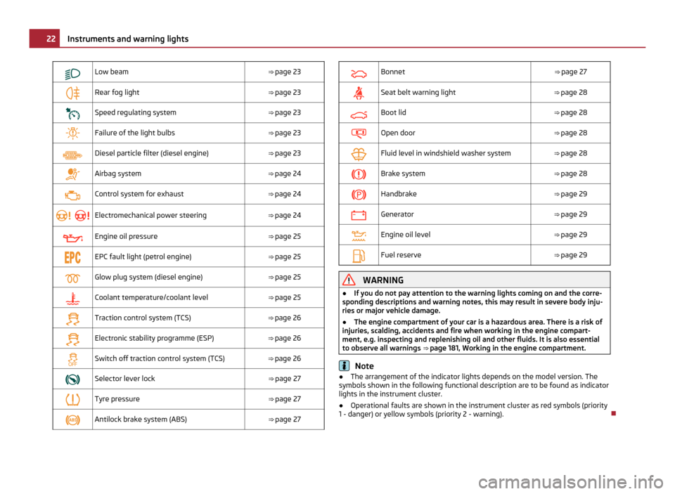
Low beam
⇒ page 23
Rear fog light
⇒ page 23
Speed regulating system
⇒ page 23
Failure of the light bulbs
⇒ page 23
Diesel particle filter (diesel engine)
⇒ page 23
Airbag system
⇒ page 24
Control system for exhaust
⇒ page 24
Electromechanical power steering
⇒ page 24
Engine oil pressure
⇒ page 25
EPC fault light (petrol engine)
⇒ page 25
Glow plug system (diesel engine)
⇒ page 25
Coolant temperature/coolant level
⇒ page 25
Traction control system (TCS)
⇒ page 26
Electronic stability programme (ESP)
⇒ page 26
Switch off traction control system (TCS)
⇒ page 26
Selector lever lock
⇒ page 27
Tyre pressure
⇒ page 27
Antilock brake system (ABS)
⇒ page 27
Bonnet
⇒ page 27
Seat belt warning light
⇒ page 28
Boot lid
⇒ page 28
Open door
⇒ page 28
Fluid level in windshield washer system
⇒ page 28
Brake system
⇒ page 28
Handbrake
⇒ page 29
Generator
⇒ page 29
Engine oil level
⇒ page 29
Fuel reserve
⇒ page 29 WARNING
● If you do not pay attention to the warning lights coming on and the corre-
sponding descriptions and warning notes, this may result in severe body inju-
ries or major vehicle damage.
● The engine compartment of your car is a hazardous area. There is a risk of
injuries, scalding, accidents and fire when working in the engine compart-
ment, e.g. inspecting and replenishing oil and other fluids. It is also essential
to observe all warnings ⇒
page 181, Working in the engine compartment. Note
● The arrangement of the indicator lights depends on the model version. The
symbols shown in the following functional description are to be found as indicator
lights in the instrument cluster.
● Operational faults are shown in the instrument cluster as red symbols (priority
1 - danger) or yellow symbols (priority 2 - warning). 22
Instruments and warning lights
Page 25 of 248
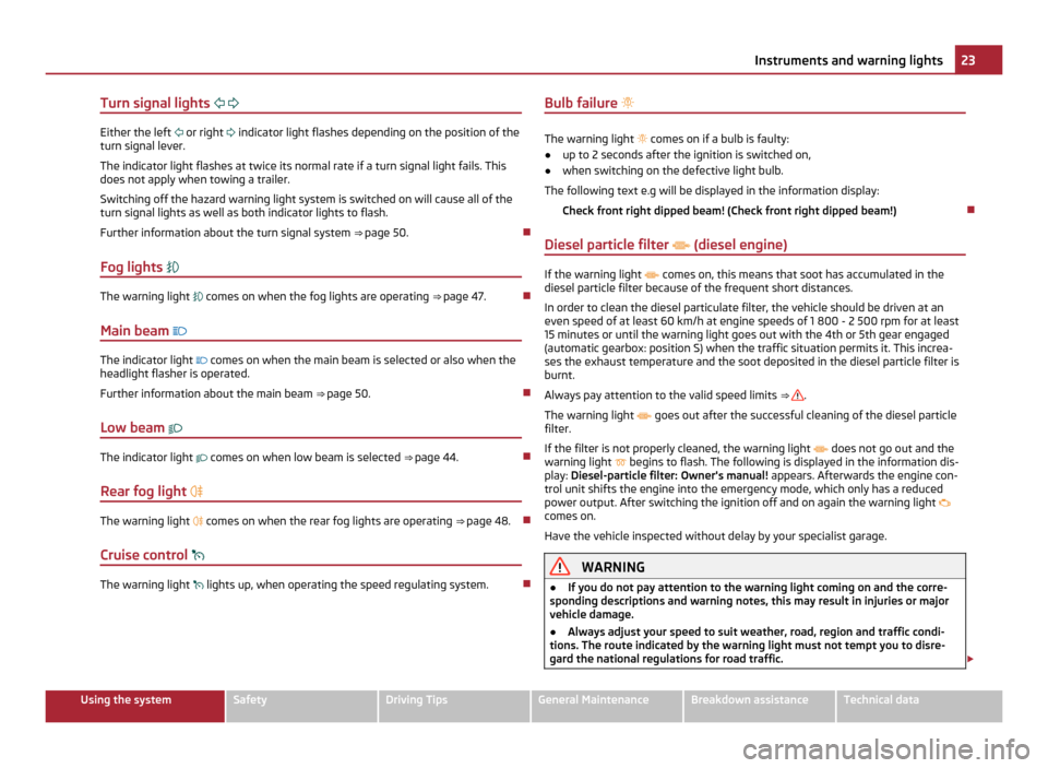
Turn signal lights
Either the left
or right indicator light flashes depending on the position of the
turn signal lever.
The indicator light flashes at twice its normal rate if a turn signal light fails. This
does not apply when towing a trailer.
Switching off the hazard warning light system is switched on will cause all of the
turn signal lights as well as both indicator lights to flash.
Further information about the turn signal system ⇒
page 50.
Fog lights The warning light
comes on when the fog lights are operating ⇒
page 47.
Main beam The indicator light
comes on when the main beam is selected or also when the
headlight flasher is operated.
Further information about the main beam ⇒
page 50.
Low beam The indicator light
comes on when low beam is selected ⇒ page 44.
Rear fog light The warning light
comes on when the rear fog lights are operating ⇒
page 48.
Cruise control The warning light
lights up, when operating the speed regulating system. Bulb failure
The warning light
comes on if a bulb is faulty:
● up to 2 seconds after the ignition is switched on,
● when switching on the defective light bulb.
The following text e.g will be displayed in the information display: Check front right dipped beam! (Check front right dipped beam!)
Diesel particle filter (diesel engine) If the warning light
comes on, this means that soot has accumulated in the
diesel particle filter because of the frequent short distances.
In order to clean the diesel particulate filter, the vehicle should be driven at an
even speed of at least 60 km/h at engine speeds of 1
800 - 2 500 rpm for at least
15 minutes or until the warning light goes out with the 4th or 5th gear engaged
(automatic gearbox: position S) when the traffic situation permits it. This increa-
ses the exhaust temperature and the soot deposited in the diesel particle filter is
burnt.
Always pay attention to the valid speed limits ⇒ .
The warning light goes out after the successful cleaning of the diesel particle
filter.
If the filter is not properly cleaned, the warning light does not go out and the
warning light begins to flash. The following is displayed in the information dis-
play: Diesel-particle filter: Owner's manual! appears. Afterwards the engine con-
trol unit shifts the engine into the emergency mode, which only has a reduced
power output. After switching the ignition off and on again the warning light
comes on.
Have the vehicle inspected without delay by your specialist garage. WARNING
● If you do not pay attention to the warning light coming on and the corre-
sponding descriptions and warning notes, this may result in injuries or major
vehicle damage.
● Always adjust your speed to suit weather, road, region and traffic condi-
tions. The route indicated by the warning light must not tempt you to disre-
gard the national regulations for road traffic. £ 23
Instruments and warning lights Using the system Safety Driving Tips General Maintenance Breakdown assistance Technical data
Page 51 of 248
Headlamp range adjustment
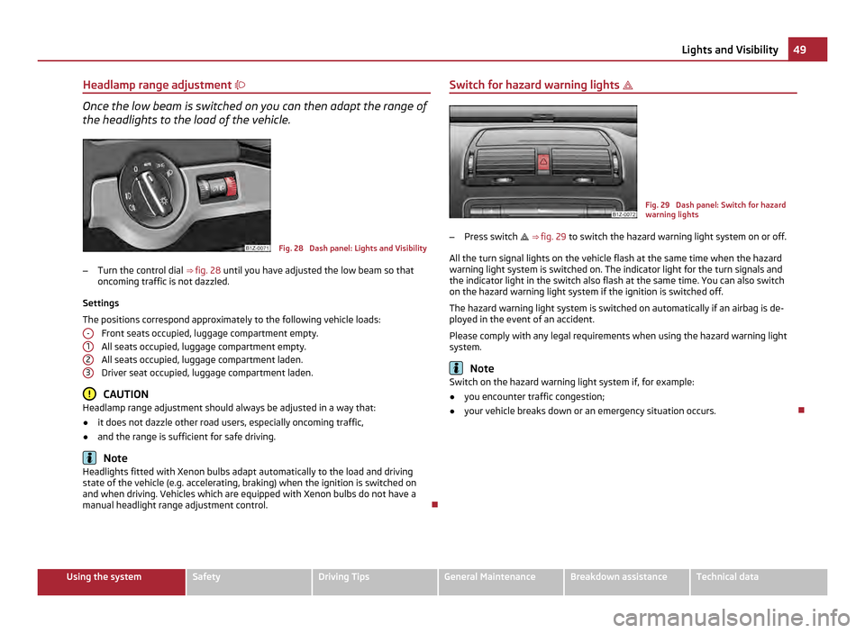
Once the low beam is switched on you can then adapt the range of
the headlights to the load of the vehicle. Fig. 28 Dash panel: Lights and Visibility
– Turn the control dial ⇒ fig. 28 until you have adjusted the low beam so that
oncoming traffic is not dazzled.
Settings
The positions correspond approximately to the following vehicle loads: Front seats occupied, luggage compartment empty.
All seats occupied, luggage compartment empty.
All seats occupied, luggage compartment laden.
Driver seat occupied, luggage compartment laden. CAUTION
Headlamp range adjustment should always be adjusted in a way that:
● it does not dazzle other road users, especially oncoming traffic,
● and the range is sufficient for safe driving. Note
Headlights fitted with Xenon bulbs adapt automatically to the load and driving
state of the vehicle (e.g. accelerating, braking) when the ignition is switched on
and when driving. Vehicles which are equipped with Xenon bulbs do not have a
manual headlight range adjustment control.
- 1
2
3 Switch for hazard warning lights
Fig. 29 Dash panel: Switch for hazard
warning lights
– Press switch ⇒ fig. 29 to switch the hazard warning light system on or off.
All the turn signal lights on the vehicle flash at the same time when the hazard
warning light system is switched on. The indicator light for the turn signals and
the indicator light in the switch also flash at the same time. You can also switch
on the hazard warning light system if the ignition is switched off.
The hazard warning light system is switched on automatically if an airbag is de-
ployed in the event of an accident.
Please comply with any legal requirements when using the hazard warning light
system. Note
Switch on the hazard warning light system if, for example:
● you encounter traffic congestion;
● your vehicle breaks down or an emergency situation occurs. 49
Lights and Visibility Using the system Safety Driving Tips General Maintenance Breakdown assistance Technical data
Page 52 of 248

The turn signal
and main beam lever The parking lights and headlight flasher are also switched on and
off using the turn signal and main beam lever.
Fig. 30 Turn signal and main beam lever
The turn signal and main beam lever perform the following functions:
Right and left turn signal light
– Push the lever upwards A or downwards
⇒ fig. 30 B .
– If you only wish to flash three times (the so-called convenience turn signal),
push the lever briefly up to the upper or lower pressure point and release it.
This function can be activated/deactivated in the Information display
⇒ page 17.
– Turn signal for changing lanes - in order to only flash briefly, move the lever up
or down to the pressure point and hold it in this position.
Main beam
– Switch on the low beam.
– Push the lever forwards in direction of arrow C (spring-tensioned position).
– If you push the lever towards the steering wheel in direction of arrow D(spring-tensioned position) the main beam is switched off.
Headlight flasher
– Pull the lever towards the steering wheel (spring-tensioned position) in direc-
tion of arrow D - the main beam and warning light
in the instrument clus-
ter come on.
Parking light
For a description of the operation, see ⇒ page 46
, Parking light. Information concerning the function of the lights.
● The turn signal system only operates when the ignition is switched on. The
corresponding warning light or in the instrument cluster also flashes.
● The turn signal is automatically cancelled after negotiating a curve.
● The indicator light flashes at twice its normal rate if a bulb of the turn signal
light fails. CAUTION
Use main beam or the headlight flasher only if this does not risk dazzling other
road users. Note
Use only in accordance with the legal requirements the described lighting and sig-
nal systems.
Interior lighting Interior vehicle lighting - Variant 1 Fig. 31 Interior vehicle lighting - Variant
1
Switching on the interior lighting
– Press switch A towards the edge of the light, the symbol
⇒
fig. 31 appears.
Switching off the interior lighting
– Press the switch A into the middle position
O.
Operating the lights with the door contact switch
– Press switch A towards the centre of the light, the symbol
appears. £50
Lights and Visibility
Page 53 of 248
Reading lights
–
Press switch B to switch the reading light on/off.
If operating lights with the door contact switch is enabled (switch A is in position
), the light will come on when:
● the vehicle is unlocked,
● one of the doors is opened,
● or the ignition key is removed.
If operating lights with the door contact switch is enabled (switch A is in position
), the light will turn off when:
● the vehicle is locked,
● the ignition is switched on,
● about 30 seconds after all the doors have been closed.
If a door remains open, or if the switch A is in position
, the interior lighting
goes out after 10
minutes to prevent the battery from discharging. Note
We recommend having these bulbs replaced by a specialist garage.
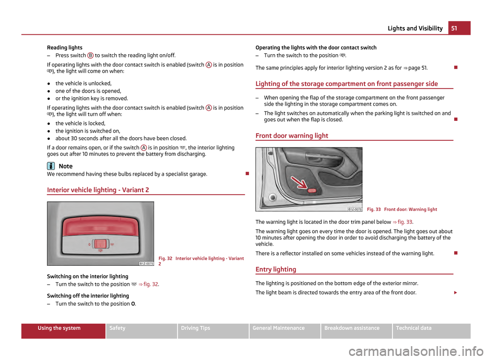
Interior vehicle lighting - Variant 2 Fig. 32 Interior vehicle lighting - Variant
2
Switching on the interior lighting
– Turn the switch to the position ⇒ fig. 32 .
Switching off the interior lighting
– Turn the switch to the position O. Operating the lights with the door contact switch
– Turn the switch to the position .
The same principles apply for interior lighting version 2 as for ⇒
page 51.
Lighting of the storage compartment on front passenger side –
When opening the flap of the storage compartment on the front passenger
side the lighting in the storage compartment comes on.
– The light switches on automatically when the parking light is switched on and
goes out when the flap is closed.
Front door warning light Fig. 33 Front door: Warning light
The warning light is located in the door trim panel below ⇒
fig. 33.
The warning light goes on every time the door is opened. The light goes out about
10 minutes after opening the door in order to avoid discharging the battery of the
vehicle.
There is a reflector installed on some vehicles instead of the warning light.
Entry lighting The lighting is positioned on the bottom edge of the exterior mirror.
The light beam is directed towards the entry area of the front door.
£ 51
Lights and Visibility Using the system Safety Driving Tips General Maintenance Breakdown assistance Technical data
Page 189 of 248
Replacing brake fluid
Brake fluid absorbs moisture. This causes the fluid to absorb moisture from the
surrounding air over a period of time. Excessive water in the brake fluid may be
the cause of corrosion in the brake system. The water content also lowers the
boiling point of the brake fluid.
Only new genuine brake fluid from
ŠKODA may be used.
The brake fluid must comply with one of the following standards or specifications:
● VW 50114
● FMVSS 116 DOT4
● DIN ISO 4925 CLASS 4
We recommend that you have the brake fluid replaced by an authorised ŠKODA
Service Partner as part of an Inspection Service. WARNING
Using old brake fluid can result in severe stress on the brakes because of the
formation of vapour bubbles in the brake system. This greatly impairs the
braking efficiency and thus also the safety of your vehicle. CAUTION
Brake fluid damages the paintwork of the vehicle. For the sake of the environment
Due to issues with disposal, the special tools and knowledge required, we recom-
mend you have the brake fluid replaced by an authorised ŠKODA Service Partner.
Battery General information Improper handling of the vehicle battery can cause damage. We therefore recom-
mend you have work on the vehicle battery carried out by an authorised
ŠKODA
service partner. There is a risk of injuries, scalding, accidents and burns when carrying out any
work on the battery and on the electrical system. For this reason, it is essential to
comply with the warning instructions ⇒ stated below and with the general ap-
plicable rules of safety. WARNING
● The battery acid is strongly corrosive and must, therefore, be handled with
the greatest of care. Always wear protective gloves, eye and skin protection
when handling batteries. Corrosive fumes in the air irritate the air passages
and lead to conjunctivitis and inflammation of the air passages in the lungs.
Battery acid corrodes dental enamel and creates deep wounds after contact
with the skin which take a long time to heal. Repeated contact with diluted
acids causes skin diseases (inflammations, ulcers, slin cracks). Acids coming in-
to contact with water are diluted accompanied by significant development of
heat.
● Do not tilt the battery otherwise battery electrolyte may flow out of the
battery vent openings. Protect the eyes with safety glasses or a shield! There
is the danger of suffering blindness! If any battery electrolyte gets into your
eye, rinse out your eye immediately with clear water for several minutes. Con-
tact a doctor without delay.
● Splashes of acid on your skin or clothes should be neutralised as soon as
possible using soap suds and then rinsed with plenty of water. If acid was
swallowed, seek immediate medical attention.
● Keep batteries out of the reach of children.
● Hydrogen is released when you charge a battery and a highly explosive gas
mixture is produced. An explosion can be caused through sparkling over dur-
ing unclamping or loosening of the cable plug while the ignition is on.
● Bridging of the poles will create a short circuit (e.g. through metal objects,
cables). Possible consequences of a short circuit: Melting of lead struts, explo-
sion and burning of the battery, jets of acid spurting out.
● It is prohibited to work with a naked flame and light, to smoke or to carry
out any activities which produce sparks. Avoid creating sparks when working
with cables and electrical devices. Strong sparking represents a risk of injury.
● Before carrying out any work on the electrical system, switch off the en-
gine, the ignition as well as all electrical components and disconnect the neg-
ative cable (-) on the battery. If you wish to replace a bulb it is sufficient to
switch off the appropriate light. £ 187
Inspecting and Replenishing Using the system Safety Driving Tips General Maintenance Breakdown assistance Technical data
Page 213 of 248
Fuses and light bulbs
Electric fuses Replacing fuses in the dash panel Defect fuses must be replaced.
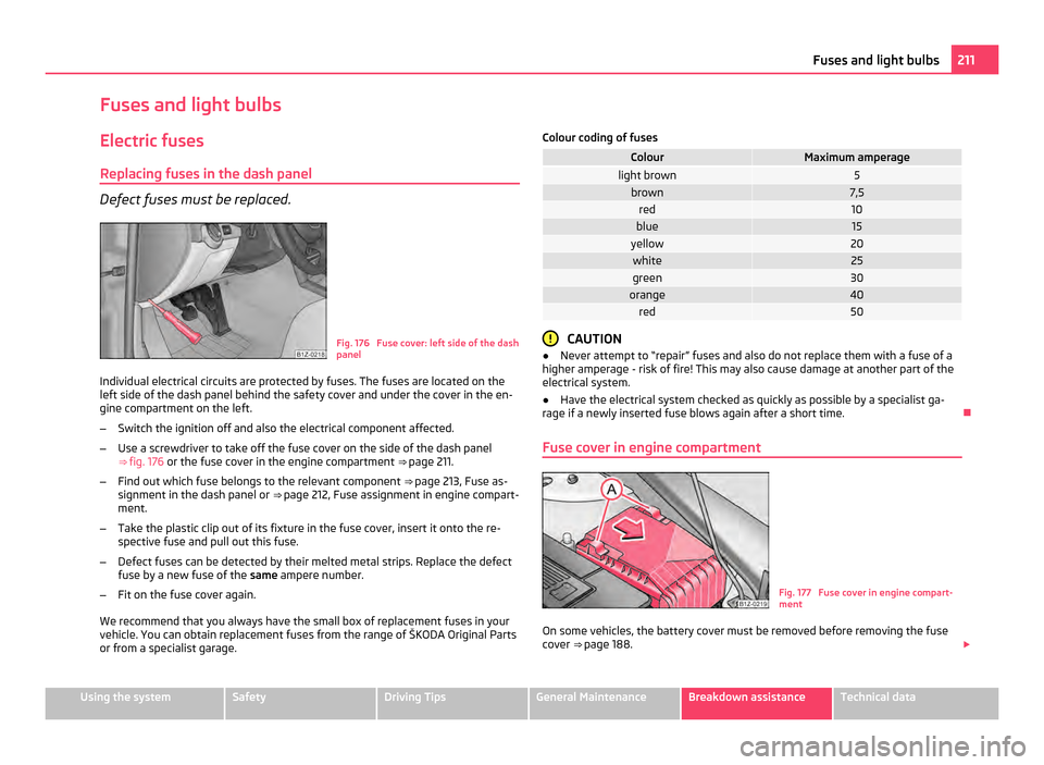
Fig. 176 Fuse cover: left side of the dash
panel
Individual electrical circuits are protected by fuses. The fuses are located on the
left side of the dash panel behind the safety cover and under the cover in the en-
gine compartment on the left.
– Switch the ignition off and also the electrical component affected.
– Use a screwdriver to take off the fuse cover on the side of the dash panel
⇒ fig. 176 or the fuse cover in the engine compartment ⇒ page 211.
– Find out which fuse belongs to the relevant component ⇒ page 213, Fuse as-
signment in the dash panel or ⇒ page 212, Fuse assignment in engine compart-
ment.
– Take the plastic clip out of its fixture in the fuse cover, insert it onto the re-
spective fuse and pull out this fuse.
– Defect fuses can be detected by their melted metal strips. Replace the defect
fuse by a new fuse of the same ampere number.
– Fit on the fuse cover again.
We recommend that you always have the small box of replacement fuses in your
vehicle. You can obtain replacement fuses from the range of
ŠKODA Original Parts
or from a specialist garage. Colour coding of fuses Colour Maximum amperage
light brown 5
brown 7,5
red 10
blue 15
yellow 20
white 25
green 30
orange 40
red 50
CAUTION
● Never attempt to
“repair” fuses and also do not replace them with a fuse of a
higher amperage - risk of fire! This may also cause damage at another part of the
electrical system.
● Have the electrical system checked as quickly as possible by a specialist ga-
rage if a newly inserted fuse blows again after a short time.
Fuse cover in engine compartment Fig. 177 Fuse cover in engine compart-
ment
On some vehicles, the battery cover must be removed before removing the fuse
cover ⇒ page 188
. £ 211
Fuses and light bulbs Using the system Safety Driving Tips General Maintenance Breakdown assistance Technical data
Page 214 of 248
Removing fuse cover
–
Move the circlips A ⇒
fig. 177 as far as the stop, the symbol appears behind
the circlip and remove the cover.
Installing fuse cover
– Position the fuse cover on the fuse box and push the circlips A as far as the
stop - the symbol is visible behind the circlip. CAUTION
● When unlocking and locking the fuse cover, it must be pressed on the sides to
the box, otherwise damage can occur to the locking mechanism.
● Carefully position the fuse cover in the engine compartment. If the cover was
not correctly positioned, water can get into the fuses and this results in a damage
to the vehicle!
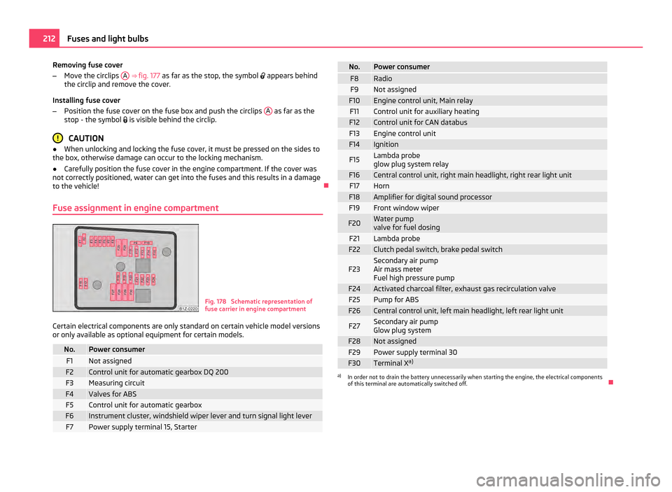
Fuse assignment in engine compartment Fig. 178 Schematic representation of
fuse carrier in engine compartment
Certain electrical components are only standard on certain vehicle model versions
or only available as optional equipment for certain models. No. Power consumer
F1 Not assigned
F2 Control unit for automatic gearbox DQ 200
F3 Measuring circuit
F4 Valves for ABS
F5 Control unit for automatic gearbox
F6 Instrument cluster, windshield wiper lever and turn signal light lever
F7 Power supply terminal 15, Starter No. Power consumer
F8 Radio
F9 Not assigned
F10 Engine control unit, Main relay
F11 Control unit for auxiliary heating
F12 Control unit for CAN databus
F13 Engine control unit
F14 Ignition
F15 Lambda probe
glow plug system relay
F16 Central control unit, right main headlight, right rear light unit
F17 Horn
F18 Amplifier for digital sound processor
F19 Front window wiper
F20 Water pump
valve for fuel dosing
F21 Lambda probe
F22 Clutch pedal switch, brake pedal switch
F23 Secondary air pump
Air mass meter
Fuel high pressure pump
F24 Activated charcoal filter, exhaust gas recirculation valve
F25 Pump for ABS
F26 Central control unit, left main headlight, left rear light unit
F27 Secondary air pump
Glow plug system
F28 Not assigned
F29 Power supply terminal 30
F30 Terminal X
a) a)
In order not to drain the battery unnecessarily when starting the engine, the electrical components
of this terminal are automatically switched off. 212
Fuses and light bulbs
Page 215 of 248
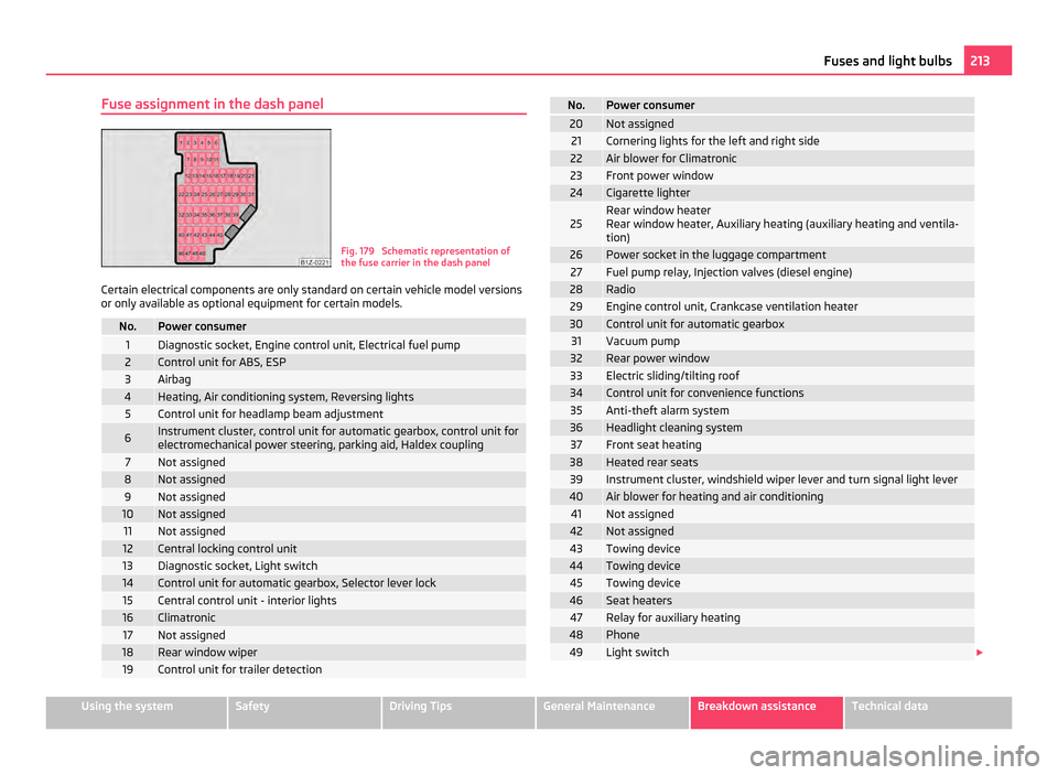
Fuse assignment in the dash panel
Fig. 179 Schematic representation of
the fuse carrier in the dash panel
Certain electrical components are only standard on certain vehicle model versions
or only available as optional equipment for certain models. No. Power consumer
1 Diagnostic socket, Engine control unit, Electrical fuel pump
2 Control unit for ABS, ESP
3 Airbag
4 Heating, Air conditioning system, Reversing lights
5 Control unit for headlamp beam adjustment
6 Instrument cluster, control unit for automatic gearbox, control unit for
electromechanical power steering, parking aid, Haldex coupling 7 Not assigned
8 Not assigned
9 Not assigned
10 Not assigned
11 Not assigned
12 Central locking control unit
13 Diagnostic socket, Light switch
14 Control unit for automatic gearbox, Selector lever lock
15 Central control unit - interior lights
16 Climatronic
17 Not assigned
18 Rear window wiper
19 Control unit for trailer detection No. Power consumer
20 Not assigned
21 Cornering lights for the left and right side
22 Air blower for Climatronic
23 Front power window
24 Cigarette lighter
25 Rear window heater
Rear window heater, Auxiliary heating (auxiliary heating and ventila-
tion)
26 Power socket in the luggage compartment
27 Fuel pump relay, Injection valves (diesel engine)
28 Radio
29 Engine control unit, Crankcase ventilation heater
30 Control unit for automatic gearbox
31 Vacuum pump
32 Rear power window
33 Electric sliding/tilting roof
34 Control unit for convenience functions
35 Anti-theft alarm system
36 Headlight cleaning system
37 Front seat heating
38 Heated rear seats
39 Instrument cluster, windshield wiper lever and turn signal light lever
40 Air blower for heating and air conditioning
41 Not assigned
42 Not assigned
43 Towing device
44 Towing device
45 Towing device
46 Seat heaters
47 Relay for auxiliary heating
48 Phone
49 Light switch
£ 213
Fuses and light bulbs Using the system Safety Driving Tips General Maintenance Breakdown assistance Technical data