high beam SKODA OCTAVIA 2011 2.G / (1Z) Owner's Manual
[x] Cancel search | Manufacturer: SKODA, Model Year: 2011, Model line: OCTAVIA, Model: SKODA OCTAVIA 2011 2.G / (1Z)Pages: 248, PDF Size: 3.79 MB
Page 49 of 248

The function Coming Home is controlled with the light sensor in the mount of the
interior rear mirror. If the light intensity is higher than the set value of the light
sensor, the Coming Home Function is not switched on after switching off the igni-
tion. Note
● If the Coming Home Function is switched on constantly, the battery will be
heavily discharged particularly in short-haul traffic.
● The switching on of the described lights should only be undertaken in accord-
ance with the legal requirements.
● You can change the illumination period for the Leaving Home Function by
means of the Information display.
Leaving Home Function This function makes it possible to switch on the lights when approaching the ve-
hicle.
Switching on Leaving Home Function
–
The light switch is in the position automatic driving lamp control .
– Unlock the vehicle with the radio remote control - the lights come on.
Depending on equipment fitted the function Leaving Home switches on the fol-
lowing lights:
● Parking lights,
● Low beam,
● Entry lighting in the exterior mirrors,
● Licence plate light.
Leaving Home Function
The function Leaving Home is controlled with the light sensor in the mount of the
interior rear mirror. If the light intensity is higher than the set value of the light
sensor, the Leaving Home Function is not switched on after unlocking the vehicle
with the radio remote control.
After unlocking the vehicle with the radio remote control, the lights come on for
10 seconds. The Leaving Home Function is also switched off after the ignition is
switched on and after locking the vehicle.
If no door is opened within 30 seconds, the lights go out and the vehicle is locked
automatically. Note
● If the Leaving Home Function is switched on constantly, the battery will be
heavily discharged particularly in short-haul traffic.
● The switching on of the described lights should only be undertaken in accord-
ance with the legal requirements.
● You can change the illumination period for the Leaving Home Function by
means of the Information display.
Tourist light This mode makes it possible to drive in countries with opposing traffic system,
driving on the left/right, without dazzling the oncoming vehicles. When the mode
“tourist light
” is active, the side to side swivel of the headlights is deactivated.
The mode “tourist light” is activated/deactivated via the Information display in the
menu:
■ Settings
■ Lights & Vision
■ Travel mode
■ Off
■ Switched on
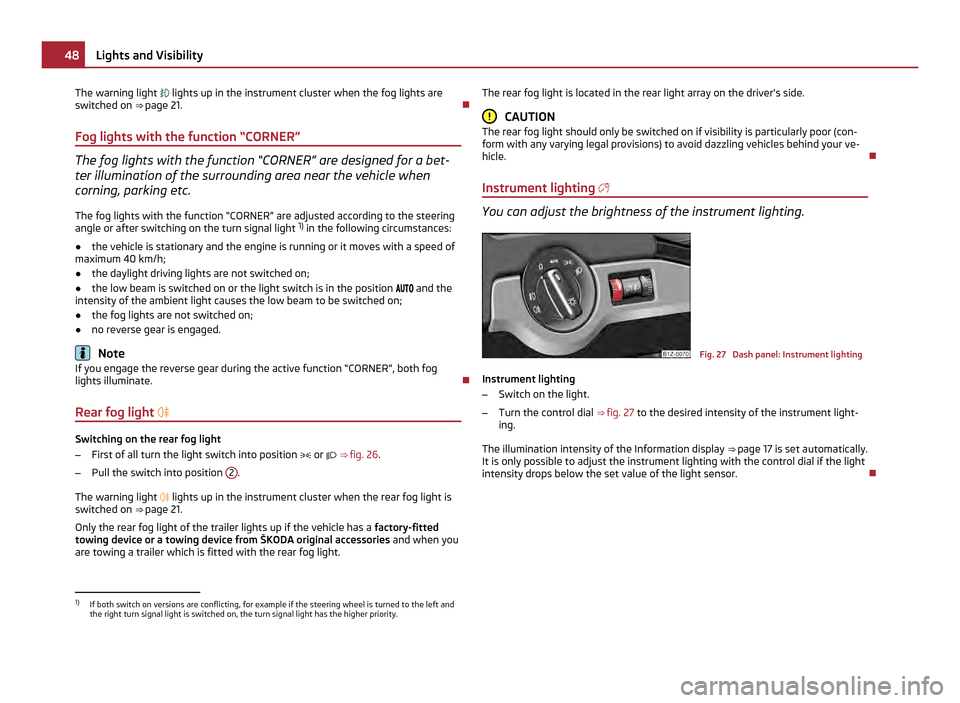
Fog lights Fig. 26 Dash panel: Light switch
Switch on the front fog lamp
– First of all turn the light switch into position or ⇒
fig. 26 .
– Pull the light switch into position 1 .
£ 47
Lights and Visibility Using the system Safety Driving Tips General Maintenance Breakdown assistance Technical data
Page 50 of 248

The warning light
lights up in the instrument cluster when the fog lights are
switched on ⇒
page 21.
Fog lights with the function “CORNER” The fog lights with the function “CORNER” are designed for a bet-
ter illumination of the surrounding area near the vehicle when
corning, parking etc.
The fog lights with the function
“CORNER” are adjusted according to the steering
angle or after switching on the turn signal light 1)
in the following circumstances:
● the vehicle is stationary and the engine is running or it moves with a speed of
maximum 40 km/h;
● the daylight driving lights are not switched on;
● the low beam is switched on or the light switch is in the position
and the
intensity of the ambient light causes the low beam to be switched on;
● the fog lights are not switched on;
● no reverse gear is engaged. Note
If you engage the reverse gear during the active function “CORNER”, both fog
lights illuminate.
Rear fog light Switching on the rear fog light
–
First of all turn the light switch into position or ⇒
fig. 26 .
– Pull the switch into position 2 .
The warning light
lights up in the instrument cluster when the rear fog light is
switched on ⇒ page 21.
Only the rear fog light of the trailer lights up if the vehicle has a factory-fitted
towing device or a towing device from ŠKODA original accessories and when you
are towing a trailer which is fitted with the rear fog light. The rear fog light is located in the rear light array on the driver's side. CAUTION
The rear fog light should only be switched on if visibility is particularly poor (con-
form with any varying legal provisions) to avoid dazzling vehicles behind your ve-
hicle.
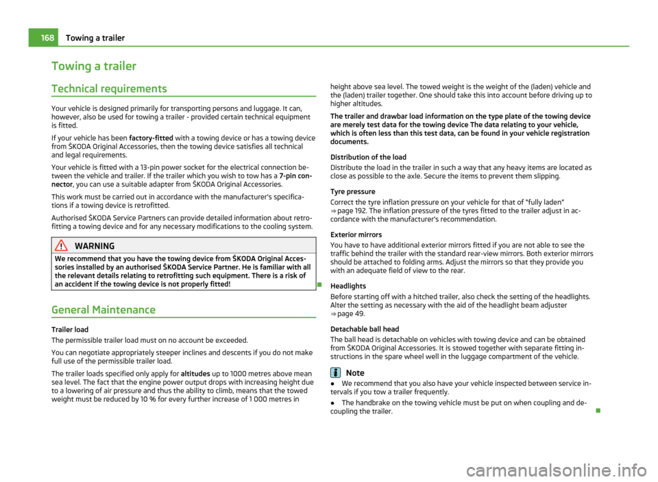
Instrument lighting You can adjust the brightness of the instrument lighting.
Fig. 27 Dash panel: Instrument lighting
Instrument lighting
– Switch on the light.
– Turn the control dial ⇒
fig. 27 to the desired intensity of the instrument light-
ing.
The illumination intensity of the Information display ⇒ page 17 is set automatically.
It is only possible to adjust the instrument lighting with the control dial if the light
intensity drops below the set value of the light sensor. 1)
If both switch on versions are conflicting, for example if the steering wheel is turned to the left and
the right turn signal light is switched on, the turn signal light has the higher priority. 48
Lights and Visibility
Page 170 of 248

Towing a trailer
Technical requirements Your vehicle is designed primarily for transporting persons and luggage. It can,
however, also be used for towing a trailer - provided certain technical equipment
is fitted.
If your vehicle has been
factory-fitted with a towing device or has a towing device
from ŠKODA Original Accessories, then the towing device satisfies all technical
and legal requirements.
Your vehicle is fitted with a 13-pin power socket for the electrical connection be-
tween the vehicle and trailer. If the trailer which you wish to tow has a 7-pin con-
nector, you can use a suitable adapter from
ŠKODA Original Accessories.
This work must be carried out in accordance with the manufacturer's specifica-
tions if a towing device is retrofitted.
Authorised ŠKODA Service Partners can provide detailed information about retro-
fitting a towing device and for any necessary modifications to the cooling system. WARNING
We recommend that you have the towing device from ŠKODA Original Acces-
sories installed by an authorised
ŠKODA Service Partner. He is familiar with all
the relevant details relating to retrofitting such equipment. There is a risk of
an accident if the towing device is not properly fitted!
General Maintenance Trailer load
The permissible trailer load must on no account be exceeded.
You can negotiate appropriately steeper inclines and descents if you do not make
full use of the permissible trailer load.
The trailer loads specified only apply for
altitudes up to 1000 metres above mean
sea level. The fact that the engine power output drops with increasing height due
to a lowering of air pressure and thus the ability to climb, means that the towed
weight must be reduced by 10 % for every further increase of 1 000 metres in height above sea level. The towed weight is the weight of the (laden) vehicle and
the (laden) trailer together. One should take this into account before driving up to
higher altitudes.
The trailer and drawbar load information on the type plate of the towing device
are merely test data for the towing device The data relating to your vehicle,
which is often less than this test data, can be found in your vehicle registration
documents.
Distribution of the load
Distribute the load in the trailer in such a way that any heavy items are located as
close as possible to the axle. Secure the items to prevent them slipping.
Tyre pressure
Correct the tyre inflation pressure on your vehicle for that of
“fully laden”
⇒ page 192. The inflation pressure of the tyres fitted to the trailer adjust in ac-
cordance with the manufacturer's recommendation.
Exterior mirrors
You have to have additional exterior mirrors fitted if you are not able to see the
traffic behind the trailer with the standard rear-view mirrors. Both exterior mirrors
should be attached to folding arms. Adjust the mirrors so that they provide you
with an adequate field of view to the rear.
Headlights
Before starting off with a hitched trailer, also check the setting of the headlights.
Alter the setting as necessary with the aid of the headlight beam adjuster
⇒ page 49.
Detachable ball head
The ball head is detachable on vehicles with towing device and can be obtained
from ŠKODA Original Accessories. It is stowed together with separate fitting in-
structions in the spare wheel well in the luggage compartment of the vehicle. Note
● We recommend that you also have your vehicle inspected between service in-
tervals if you tow a trailer frequently.
● The handbrake on the towing vehicle must be put on when coupling and de-
coupling the trailer. 168
Towing a trailer
Page 217 of 248

WARNING
● Bulbs H7 and H1 are pressurised and may burst when changing the bulb -
risk of injury!
● It is recommended to wear gloves and safety glasses when changing a
bulb.
● Gas discharge bulbs (xenon bulbs) operate with a high voltage, professio-
nal knowledge is required - danger to life! CAUTION
Do not take hold of the glass bulb with naked fingers (even the smallest amount
of dirt reduces the working life of the light bulb). Use a clean cloth, serviette or
something similar. Note
This Owner's Manual only describes the replacement of bulbs where it is assumed
that no major complications will arise. Other light bulbs should be changed by your
specialist garage.
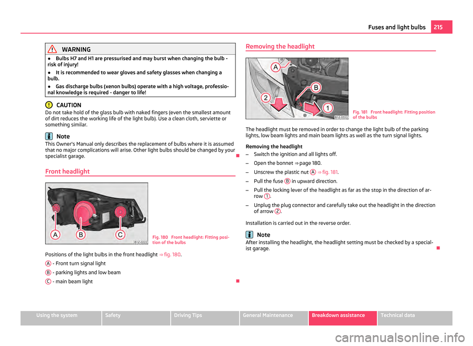
Front headlight Fig. 180 Front headlight: Fitting posi-
tion of the bulbs
Positions of the light bulbs in the front headlight ⇒ fig. 180 .
A - Front turn signal light
B - parking lights and low beam
C - main beam light
Removing the headlight
Fig. 181 Front headlight: Fitting position
of the bulbs
The headlight must be removed in order to change the light bulb of the parking
lights, low beam lights and main beam lights as well as the turn signal lights.
Removing the headlight
– Switch the ignition and all lights off.
– Open the bonnet ⇒ page 180 .
– Unscrew the plastic nut A
⇒ fig. 181 .
– Pull the fuse B in upward direction.
– Pull the locking lever of the headlight as far as the stop in the direction of ar-
row 1 .
– Unplug the plug connector and carefully take out the headlight in the direction
of arrow 2 .
Installation is carried out in the reverse order. Note
After installing the headlight, the headlight setting must be checked by a special-
ist garage. 215
Fuses and light bulbs Using the system Safety Driving Tips General Maintenance Breakdown assistance Technical data