weight SKODA OCTAVIA 2012 2.G / (1Z) Owner's Manual
[x] Cancel search | Manufacturer: SKODA, Model Year: 2012, Model line: OCTAVIA, Model: SKODA OCTAVIA 2012 2.G / (1Z)Pages: 222, PDF Size: 13.52 MB
Page 66 of 222
›Push the lever A
» Fig. 50 and fold the seat backrest completely forwards.
Folding backwards›
Hold the rear outer seat belt
C
» Fig. 50 against the side trim panel.
›
Then push the seat backrest back into the upright position until the securing
knob
A
clicks into place – check by pulling on the seat backrest » .
›
Make sure that the red pin
B
is hidden.
WARNING■
The belts and the belt locks must be in their original position after folding
back the seat backrests – they must be ready to use.■
The seat backrests must be securely interlocked in position so that no ob-
jects in the luggage compartment can slide into the passenger compartment if
there is sudden braking – risk of injury.
■
Ensure that the rear seat backrests are properly engaged. It is only then that
the three-point seat belt for the middle seat can reliably fulfil its function.
CAUTION
Ensure that the seat belts are not damaged when operating the seat backrests. Under no circumstances must the rear seat belts be jammed by the folded back
seat backrests.
Rear armrest
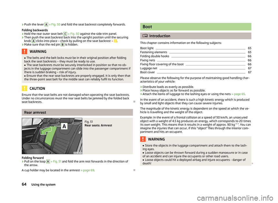
Fig. 51
Rear seats: Armrest
Folding forward
›
Pull on the loop
A
» Fig. 51 and fold the arm rest forwards in the direction of
the arrow.
A cup holder may be located in the armrest » page 69.
Boot
Introduction
This chapter contains information on the following subjects:
Boot light
65
Fastening elements
65
Folding double hooks
66
Fixing nets
66
Fixing floor covering of the boot
66
Luggage net
67
Boot cover
67
Please observe the following for the purpose of maintaining good handling char-
acteristics of your vehicle:
›
Distribute loads as evenly as possible.
›
Place heavy objects as far forward as possible.
›
Attach the items of luggage to the lashing eyes or using the nets » page 65.
In the event of an accident, there is such a high kinetic energy which is produced
by small and light objects that they can cause severe injuries.
The magnitude of the kinetic energy is dependent on the speed at which the ve-
hicle is travelling and the weight of the object.
Example: In the event of a frontal collision at a speed of 50 km/h, an unsecured
object with a weight of 4.5 kg produces an energy, which corresponds to 20 times
its own weight. This means that it results in a weight of approx. 90 kg “ ”. You can imagine the injuries that can occur, if this “object” flies through the interior com-partment and hits an occupant.
WARNING■ Store the objects in the luggage compartment and attach them to the lash-
ing eyes.■
Loose objects can be thrown forward during a sudden manoeuvre or in case
of an accident and can injure the occupants or other road users.
■
Loose objects could hit a deployed airbag and injure occupants - danger of
death!
64Using the system
Page 67 of 222
WARNING (Continued)■Please note that the handling properties of the vehicle may be affected
when transporting heavy objects as the centre of gravity can be displaced –
risk of accident! The speed and style of driving must be adjusted accordingly.■
If the items of luggage or objects are attached to the lashing eyes with un-
suitable or damaged lashing straps, injuries can occur in the event of braking manoeuvres or accidents. To prevent items of luggage from moving around,
always use suitable lashing straps which must be firmly attached to the lash-
ing eyes.
■
The items carried in the luggage compartment must be stored in such a way
that no objects are able to slip forward if any sudden driving or braking ma-
noeuvres are undertaken – risk of injury!
■
When transporting objects in the luggage compartment that has been en-
larged by folding the rear seats forward, ensure the safety of the passengers transported on the other rear seats » page 140, Correct seated position for
the occupants on the rear seats .
■
Do not drive with the luggage compartment lid fully opened or slightly ajar
otherwise exhaust gases may get into the interior of the vehicle – risk of poi-
soning!
■
Do not exceed the permissible axle loads and permissible gross weight of
the vehicle – risk of accident!
■
Do not transport people in the luggage compartment!
CAUTION
Make sure that transported objects with sharp edges do not damage the follow-
ing:■
heating elements in the rear window;
■
Elements of the aerial integrated in the rear window.
Note
Tyre pressure must be adjusted to the load » page 182
, Tyre life .
Boot light
First read and observe the introductory information and safety warn-
ings
on page 64.
The light switches on/off when the boot lid is opened or closed.
NoteIf the boot lid is open and the ignition switched off, the light will extinguish auto-
matically after around 10 minutes.
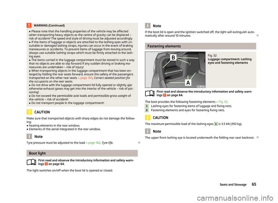
Fastening elements
Fig. 52
Luggage compartment: Lashing
eyes and fastening elements
First read and observe the introductory information and safety warn- ings on page 64.
The boot provides the following fastening elements » Fig. 52.
Lashing eyes for fastening items of luggage and fixing nets.
Fastening elements and eyes for fastening fixing nets.
CAUTION
The maximum permissible load of the lashing eyes A is 3.5 kN (350 kg).
Note
The upper front lashing eye is located underneath the folding rear seat backrest.
AB65Seats and Stowage
Page 68 of 222
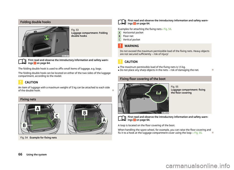
Folding double hooksFig. 53
Luggage compartment: Folding
double hooks
First read and observe the introductory information and safety warn-
ings on page 64.
The folding double hook is used to affix small items of luggage, e.g. bags.
The folding double hook can be located on either of the two sides of the luggage
compartment, according to the model.
CAUTION
An item of luggage with a maximum weight of 5 kg can be attached to each side
of the double hook.
Fixing nets
Fig. 54
Example for fixing nets
First read and observe the introductory information and safety warn- ings on page 64.
Examples for attaching the fixing nets » Fig. 54.
Horizontal pocket
Floor net
Vertical pocket
WARNINGDo not exceed the maximum permissible load of the fixing nets. Heavy objects are not secured sufficiently – risk of injury!
CAUTION
■ The maximum permissible load of the fixing nets is 1.5 kg.■Do not place any sharp objects in the nets – risk of damaging the net.
Fixing floor covering of the boot
Fig. 55
Luggage compartment: fixing
the floor covering
First read and observe the introductory information and safety warn- ings on page 64.
A loop is located on the floor covering of the boot.
When handling the spare wheel, for example, you can raise the floor covering andfix it to a hook at the luggage compartment cover using the loop » Fig. 55.
ABC66Using the system
Page 69 of 222
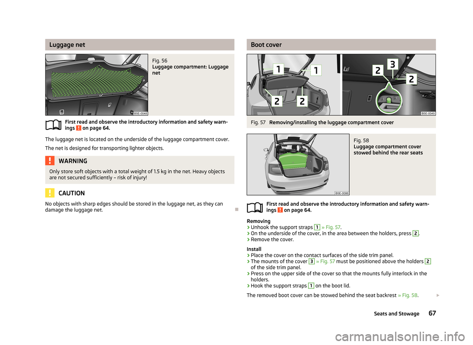
Luggage netFig. 56
Luggage compartment: Luggage
net
First read and observe the introductory information and safety warn-
ings on page 64.
The luggage net is located on the underside of the luggage compartment cover.
The net is designed for transporting lighter objects.
WARNINGOnly store soft objects with a total weight of 1.5 kg in the net. Heavy objects
are not secured sufficiently – risk of injury!
CAUTION
No objects with sharp edges should be stored in the luggage net, as they can
damage the luggage net.
Boot coverFig. 57
Removing/installing the luggage compartment cover
Fig. 58
Luggage compartment cover
stowed behind the rear seats
First read and observe the introductory information and safety warn-
ings on page 64.
Removing
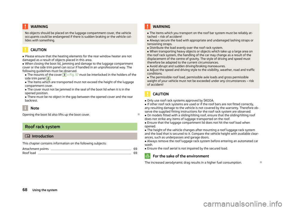
›
Unhook the support straps
1
» Fig. 57 .
›
On the underside of the cover, in the area between the holders, press
2
.
›
Remove the cover.
Install
›
Place the cover on the contact surfaces of the side trim panel.
›
The mounts of the cover
3
» Fig. 57 must be positioned above the holders
2
of the side trim panel.
›
Press on the upper side of the cover so that the mounts fully interlock in the
holders.
›
Hook the support straps
1
on the boot lid.
The removed boot cover can be stowed behind the seat backrest » Fig. 58.
67Seats and Stowage
Page 70 of 222
WARNINGNo objects should be placed on the luggage compartment cover, the vehicle
occupants could be endangered if there is sudden braking or the vehicle col-
lides with something.
CAUTION
■ Please ensure that the heating elements for the rear window heater are not
damaged as a result of objects placed in this area.■
When closing the boot lid, jamming and damage to the luggage compartment
cover or the side trim panel can occur if handled in an unprofessional way. The following guidelines must be observed. ■ The mounts of the cover
3
» Fig. 57 must be interlocked in the holders of the
side trim panel
2
.
■ The items which are transported must not exceed the height of the luggage
compartment cover. ■ The cover must not be jammed in the seal of the boot lid when it is in the
opened position.
■ There must be no object in the gap between the opened cover and the rear
backrest.
Note
Opening the boot lid also lifts up the boot cover.
Roof rack system
Introduction
This chapter contains information on the following subjects:
Attachment points
69
Roof load
69WARNING■ The items which you transport on the roof bar system must be reliably at-
tached – risk of accident!■
Always secure the load with appropriate and undamaged lashing straps or
tensioning straps.
■
Distribute the load evenly over the roof rack system.
■
When transporting heavy objects or objects which take up a large area on
the roof rack system, the handling of the car may change as a result of the displacement of the centre of gravity. The style of driving and speed musttherefore be adapted to the current circumstances.
■
Avoid abrupt and sudden driving/braking manoeuvres.
■
Adjust the speed and driving style to the visibility, weather, road and traffic
conditions.
■
The permissible roof load, permissible axle loads and gross permissible
weight of your vehicle must not be exceeded under any circumstances – risk
of accident!
CAUTION
■ Only use roof rack systems approved by ŠKODA.■If other roof rack systems are used or if the roof bars are not fitted correctly,
any resulting damage to the vehicle is not covered by the warranty. Therefore ob-
serve the supplied fitting instructions for the roof rack system are observed.■
On models fitted with a sliding/tilting roof, ensure that the sliding/tilting roof
does not strike any items of luggage transported on the roof.
■
Ensure that the luggage compartment lid does not hit the roof load when
opened.
■
The height of the vehicle changes after mounting a roof luggage rack system
and the load that is secured to it. Compare the vehicle height with available clear-
ances, such as underpasses and garage doors.
■
Always remove the roof luggage rack system before entering an automated car
wash.
■
Ensure the roof aerial is not impaired by the secured load.
For the sake of the environment
The increased aerodynamic drag results in a higher fuel consumption.
68Using the system
Page 71 of 222
Attachment pointsFig. 59
Attachment points for roof bars
First read and observe the introductory information and safety warn- ings
on page 68.
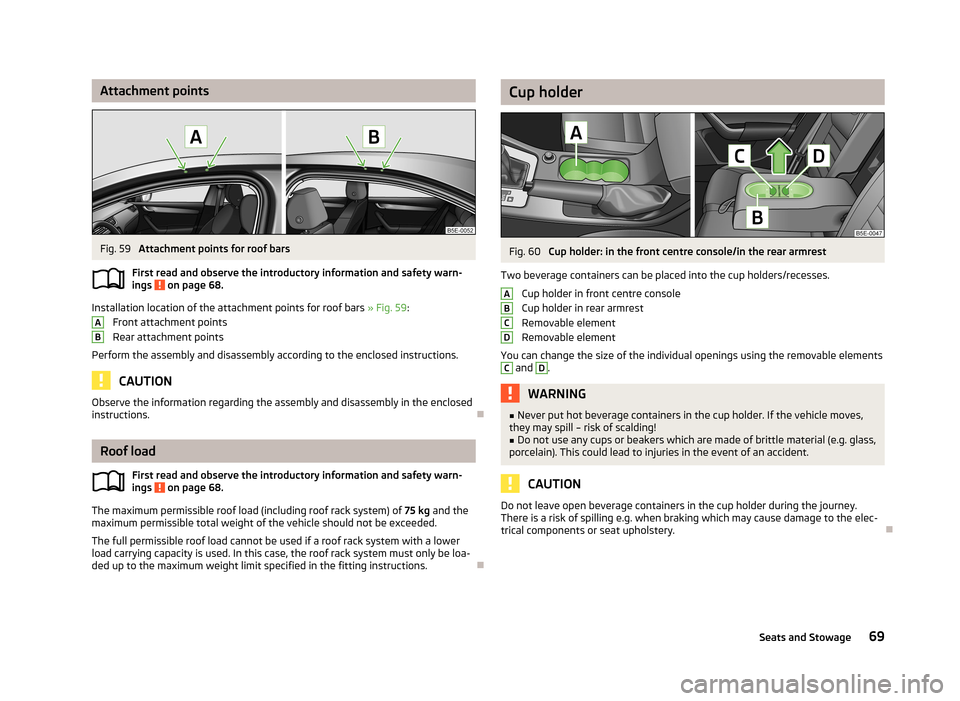
Installation location of the attachment points for roof bars » Fig. 59:
Front attachment points
Rear attachment points
Perform the assembly and disassembly according to the enclosed instructions.
CAUTION
Observe the information regarding the assembly and disassembly in the enclosed
instructions.
Roof load
First read and observe the introductory information and safety warn-
ings
on page 68.
The maximum permissible roof load (including roof rack system) of 75 kg and the
maximum permissible total weight of the vehicle should not be exceeded.
The full permissible roof load cannot be used if a roof rack system with a lower
load carrying capacity is used. In this case, the roof rack system must only be loa-
ded up to the maximum weight limit specified in the fitting instructions.
ABCup holderFig. 60
Cup holder: in the front centre console/in the rear armrest
Two beverage containers can be placed into the cup holders/recesses. Cup holder in front centre console
Cup holder in rear armrest
Removable element
Removable element
You can change the size of the individual openings using the removable elements
C
and
D
.
WARNING■ Never put hot beverage containers in the cup holder. If the vehicle moves,
they may spill – risk of scalding!■
Do not use any cups or beakers which are made of brittle material (e.g. glass,
porcelain). This could lead to injuries in the event of an accident.
CAUTION
Do not leave open beverage containers in the cup holder during the journey.
There is a risk of spilling e.g. when braking which may cause damage to the elec-
trical components or seat upholstery.ABCD69Seats and Stowage
Page 78 of 222

Stowage compartment below front passenger seatFig. 73
Front passenger seat: Stowage
compartment
Open/close
›
Pull the handle to position
1
» Fig. 73 . The compartment opens out in the di-
rection of the arrow
2
.
›
When closing the compartment, hold the handle until the compartment is closed.
WARNINGThe storage compartment must always be closed when driving for safety rea-
sons.
CAUTION
The storage compartment is designed for storing small objects of up to 1.5 kg. in weight.
Front armrest with storage compartmentFig. 74
Armrest: Stowage compartment
The armrest is adjustable for height and length.
Opening/closing the cover of the stowage compartment
›
Pull and open the cover of the armrest using the handle
A
in the direction of
the arrow
1
» Fig. 74 .
›
Open the lid to the stop, only then can it be folded downwards and against the
direction of the arrow
1
.
Adjusting the height of the armrest
›
First of all fold the cover downwards and then lift it in the direction of the arrow
1
» Fig. 74 into one of the 4 fixed positions.
Adjusting the length of the armrest
›
Move the lid into the desired position in the direction of the arrow
2
» Fig. 74 .
The area
B
» Fig. 74 of the stowage compartment is designed for the storage of
objects with a maximum size of 98 mm x 104 mm x 142 mm.
The area
C
of the stowage compartment is designed for the storage of smaller
objects.
Note
Push the armrest cover all the way back to the stop before applying the hand-
brake.
76Using the system
Page 80 of 222
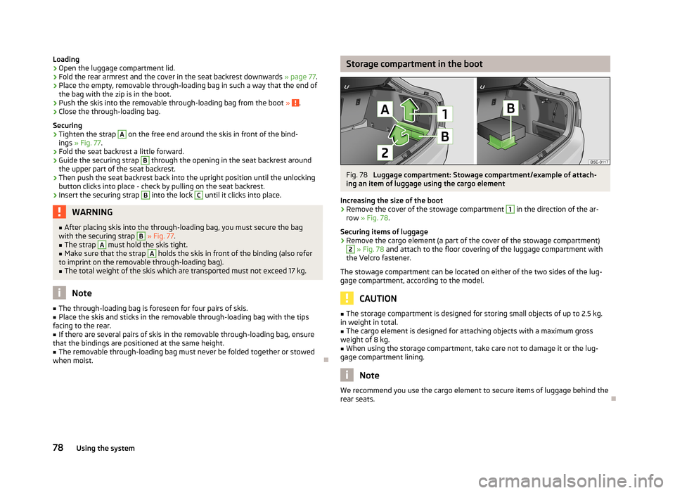
Loading›Open the luggage compartment lid.›
Fold the rear armrest and the cover in the seat backrest downwards » page 77.
›
Place the empty, removable through-loading bag in such a way that the end of
the bag with the zip is in the boot.
›
Push the skis into the removable through-loading bag from the boot » .
›
Close the through-loading bag.
Securing
›
Tighten the strap
A
on the free end around the skis in front of the bind-
ings » Fig. 77 .
›
Fold the seat backrest a little forward.
›
Guide the securing strap
B
through the opening in the seat backrest around
the upper part of the seat backrest.
›
Then push the seat backrest back into the upright position until the unlocking button clicks into place - check by pulling on the seat backrest.
›
Insert the securing strap
B
into the lock
C
until it clicks into place.
WARNING■ After placing skis into the through-loading bag, you must secure the bag
with the securing strap B » Fig. 77 .■
The strap
A
must hold the skis tight.
■
Make sure that the strap
A
holds the skis in front of the binding (also refer
to imprint on the removable through-loading bag).
■
The total weight of the skis which are transported must not exceed 17 kg.
Note
■ The through-loading bag is foreseen for four pairs of skis.■Place the skis and sticks in the removable through-loading bag with the tips
facing to the rear.■
If there are several pairs of skis in the removable through-loading bag, ensure
that the bindings are positioned at the same height.
■
The removable through-loading bag must never be folded together or stowed
when moist.
Storage compartment in the bootFig. 78
Luggage compartment: Stowage compartment/example of attach-
ing an item of luggage using the cargo element
Increasing the size of the boot
›
Remove the cover of the stowage compartment
1
in the direction of the ar-
row » Fig. 78 .
Securing items of luggage
›
Remove the cargo element (a part of the cover of the stowage compartment)
2
» Fig. 78 and attach to the floor covering of the luggage compartment with
the Velcro fastener.
The stowage compartment can be located on either of the two sides of the lug-
gage compartment, according to the model.
CAUTION
■ The storage compartment is designed for storing small objects of up to 2.5 kg.
in weight in total.■
The cargo element is designed for attaching objects with a maximum gross
weight of 8 kg.
■
When using the storage compartment, take care not to damage it or the lug-
gage compartment lining.
Note
We recommend you use the cargo element to secure items of luggage behind the
rear seats.
78Using the system
Page 105 of 222
Information about convenience consumers and the amount of fuel con-sumed » operating instructions for Infotainment , chapter Setting vehicle systems
(CAR button) .
A maximum of three convenience consumers are displayed in the Infotainment
display- the top 3 in terms of energy consumption.
You can decide to switch off the consumers or to set them to a lower level to re-duce the level of fuel consumption.
Checking tyre inflation pressures
Tyres which are correctly inflated save fuel.
Always ensure the tyre inflation pressure is correct. If the inflation pressure is too
low, the tyres must overcome a higher rolling resistance. This will not only in-
crease fuel consumption but also tyre wear and the driving behaviour will worsen.
Always check the tyre inflation pressure when the tyres are cold.
Avoid unnecessary ballast
Transporting ballast costs fuel.
Every additional kilogram in weight increases the fuel consumption. We there-
fore recommend you do not travel with any unnecessary weight.
It is particularly in town traffic, when one is accelerating quite often, that the ve-
hicle weight will have a significant effect upon the fuel consumption. A rule of
thumb here is that an increase in weight of 100 kilograms will cause an increase
in fuel consumption of about 1 litre/100 kilometres.
At a speed of 100 - 120 km/h, a vehicle fitted with a roof rack cross member with-
out a load will use about 10 % more fuel than normal due to the increased aero- dynamic drag.
Regular servicing
A poorly tuned engine uses an unnecessarily high amount of fuel.
By having your vehicle regularly maintained by a ŠKODA specialist garage, you
create the conditions needed for driving economically. The maintenance state of your vehicle has a positive effect on traffic safety and value retention.
A poorly tuned engine can result in a fuel consumption which is 10 % higher than normal!
Check the oil at regular intervals, e.g. when filling up. Oil consumption is depend-
ent to a considerable extent on the load and speed of the engine. Oil consump-
tion could be as high as 0.5 litres/1 000 km depending on your style of driving.
It is quite normal that a new engine has a higher oil consumption at first, and rea- ches its lowest level only after a certain running in time. The oil consumption of anew vehicle can therefore only be correctly assessed after driving about5 000 km.
For the sake of the environment
■ Additional improvements to the fuel economy can be made by using synthetic
high-lubricity oils.■
Regularly check the ground under the vehicle. Have your vehicle inspected by a
ŠKODA specialist garage if you find any stains caused by oil or other fluids on the
floor.
Note
We recommend that your vehicle is serviced on a regular basis by a ŠKODA Part-
ner.
Environmental compatibility
Environmental protection has played a major role in the design, selection of mate-
rials and manufacture of your new ŠKODA. Particular emphasis has been placed
on the following points:
Design measures › Joints designed to be easily detached.
› Simplified disassembly due to the modular structure system.
› Improved purity of different classes of materials.
› Identification of all plastic parts in accordance with VDA Recommendation 260.
› Reduced fuel consumption and exhaust emission CO
2.
› Minimum fuel leakage during accidents.
› Reduced noise.
Choice of materials › Extensive use of recyclable material.
› Air conditioning filled with CFC-free refrigerant.
103Driving and the Environment
Page 111 of 222
CAUTION■If the lever is held firm and not pushed downwards as far as it can go, it will go
back up after the ball rod is removed and will not latch into the ready position.
The ball rod then needs to be brought into this position before the next time it is installed.■
Stow the ball rod in the ready position with the key inserted in the box. When
doing so, make the side opposite to the inserted key face downwards - risk of damaging the key!
■
Do not use excessive force when handling the operating lever (e.g. do not climb
on it)!
Note
Remove any dirt from the ball rod before stowing it away in the box with the ve-
hicle tool kit.
Operation and maintenance
First read and observe the introductory information and safety warn-ings
on page 106.
Seal the mounting recess with the cap to prevent any ingress of dirt.
Always check the ball head before hitching a trailer. Use a suitable lubricating grease where necessary.
Include the protective cap when stowing away the ball rod to protect the boot
from getting contaminated.
In the event of dirt, clean the surfaces of the mounting recess and treat with a
suitable preservative.
CAUTION
Apply lubricating grease to the upper part of the mounting recess. Make sure you
do not remove any grease.
Loading a trailer
The vehicle/trailer combination must be balanced. whereby the maximum permis- sible drawbar load must be utilised. If the drawbar load is too low, it jeopardisesthe performance of the vehicle/trailer combination.
Distribution of the load
Distribute the load in the trailer in such a way that heavy items are located as
close to the axle as possible. Secure the items from slipping.
The distribution of the weight is very poor if your vehicle is unladen and the trail-
er is laden. Drive at a particularly low speed if you cannot avoid driving with this
combination.
Tyre pressure
Correct the tyre inflation pressure on your vehicle for a “full load” » page 182,
Tyre life .
Trailer load
The permissible trailer load must not be exceeded under any circumstan-
ces » page 207 , Technical data .
The trailer loads specified apply only to altitudes up to 1 000 metres above mean
sea level.
The engine output falls as the height increases, as does the ability to climb.
Therefore, for every additional 1 000 m in height (every one begun), the maximum
permissible towed weight must be reduced by 10 %.
The towed weight comprises the actual weight of the (loaded) towing vehicle and the (loaded) trailer.
The trailer and drawbar load information on the type plate of the towing device are merely test data for the towing device. The vehicle-specific values are de-tailed in the vehicle documents.WARNING■ Do not exceed the maximum permissible axle and drawbar load and the
maximum permissible total or towed weight of the vehicle and the trailer -
risk of accident and serious injuries!■
Always drive particularly carefully with the trailer.
■
Slipping loads can significantly affect the stability and safety of the vehicle/
trailer combination - risk of accident and serious injuries!
109Towing a trailer