change wheel SKODA OCTAVIA 2012 3.G / (5E) Owner's Manual
[x] Cancel search | Manufacturer: SKODA, Model Year: 2012, Model line: OCTAVIA, Model: SKODA OCTAVIA 2012 3.G / (5E)Pages: 222, PDF Size: 13.52 MB
Page 6 of 222
Seat belts142Seat belts142
Airbag system
146
Description of the airbag system
146
Front airbags
147
Driver’s knee airbag
148
Side airbags
149
Head airbags
150
Deactivating airbags
151
Passenger protection system
153
Introductory information
153
Activating the system
153
Transporting children safely
154
Child seat
154
General Maintenance
Taking care of and cleaning the vehicle
159
Taking care of your vehicle
159
Accessories, changes and replacement of
parts
165
Inspecting and replenishing
167
Fuel
167
Engine compartment
169
Vehicle battery
176
Wheels
181
Tyres and wheel rims
181
Do-it-yourself
Do-it-yourself
188
First-aid kit and warning triangle
188
Fire extinguisher
188
Vehicle tool kit
188
Changing a wheel
189
Tyre repair
192Jump-starting195Towing the vehicle196
Fuses and light bulbs
199
Fuses
199
Bulbs
202
Technical data
Technical data
207
Introductory information
207
Vehicle identification data
207
Dimensions
208
Specifications and engine oil capacity
209
Vehicle-specific information depending on engine type
210
Index
4Table of Contents
Page 23 of 222
Information system
Introductory information
The information system provides the driver with alerts and messages about indi-
vidual vehicle systems. These alerts and messages appear in the display of the in- strument cluster
2
» Fig. 2 on page 9.
The following is displayed in the information system:
› The outside temperature
» page 21;
› Recommended gear
» page 21;
› Door, boot lid and bonnet warning
» page 21;
› Eco tips
» page 21 ;
› Service Interval Display
» page 11;
› Auto Check Control
» page 12
› some warning lights
» page 12;
› Driving data
» page 22;
› Warning against excessive speeds
» page 24
› Data on the information display
» page 25;
› Traffic sign recognition
» page 25;
› Fatigue detection system
» page 27;
› Selector lever positions for an automatic gearbox
» page 130;
› Information and alerts in the Assist systems
» page 112.
Outside temperature
The current outside temperature is indicated in the display of the instrument cluster.
If the outside temperature drops below +4 °C while driving, a snow flake symbol
(warning signal for ice on the road) appears before the temperature indicator and
an audible signal will sound.
If the outside temperature is less than +4 °C when the ignition is turned on, a
snow flake symbol appears in the display and an acoustic signal sounds. After
pressing the rocker switch
A
or the adjustment wheel
D
» Fig. 3 on page 22,
the function shown last is indicated.
WARNINGEven at temperatures around +4 °C, black ice may still be on the road surface!
Do not only rely upon the information given on the outside temperature dis-
play that there is no ice on the road.
Recommended gear
In order to minimise the fuel consumption, a recommendation for shifting into an- other gear is indicated in the display.
Information about the currently-selected gear is shown in the upper part of the
display. When the system determines that a change in gear is required, the arrow
symbol
and the recommended gear appears next to the current gear indication.
For instance, if
appears in this display, this means it is recommended that
you shift from 3rd into 4th gear.
WARNINGThe driver is always responsible for selecting the correct gear in different driv-
ing situations, such as overtaking.
Door, boot lid and bonnet warning
If at least one door is open, or the boot or bonnet is open, the instrument cluster
display indicates the relevant open door or boot/bonnet.
An acoustic signal will also sound if you drive the vehicle above 6 km/h.
Eco tips
To minimise fuel consumption, fuel economy tips can appear in the display.
Eco tips are indicated next to the letters ECO-TIP.
For instance, if the air-condition is on and a window is open, the following mes- sage appears ECO TIP Air conditioning switched on: close windows.
Eco tips display must be activated in the Infotainment » operating instructions for
Infotainment , chapter Vehicle settings .
21Information system
Page 26 of 222
Average speed
The average speed since the memory was last erased is shown in the display
in km/hour » page 22. To determine the average speed over a certain period of
time, set the memory to zero at the start of the measurement » page 22.
After erasing the memory, no average speed data will appear for approx. the first
300 m driven.
The display is updated regularly while you are driving. The average speed data is updated regularly while you are driving.
Distance travelled
The distance driven since the memory was last erased appears in the display.
If you want to measure the distance travelled from a particular moment in time on, at this moment, reset the memory by setting the button to zero » page 22.
The maximum distance indicated in both memories is 9 999 km. The indicator is
automatically set back to zero if this period is exceeded.
Driving time
The driving time which has elapsed since the memory was last erased, appears in
the display. If you want to measure the time travelled from a particular moment intime on, at this moment, reset the memory by setting the button tozero » page 22 .
The maximum distance indicated in both memories is 99 hours and 59 minutes. The indicator is set back to zero if this period is exceeded.
Convenience consumers
The consumption display for the convenience consumers in l/h.
Together with the consumption display, a list of three convenience consumers with the highest consumption is also displayed.
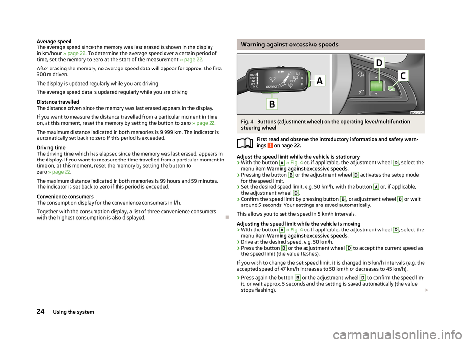
Warning against excessive speedsFig. 4
Buttons (adjustment wheel) on the operating lever/multifunction
steering wheel
First read and observe the introductory information and safety warn-ings
on page 22.
Adjust the speed limit while the vehicle is stationary
›
With the button
A
» Fig. 4 or, if applicable, the adjustment wheel
D
, select the
menu item Warning against excessive speeds .
›
Pressing the button
B
or the adjustment wheel
D
activates the setup mode
for the speed limit.
›
Set the desired speed limit, e.g. 50 km/h, with the button
A
or, if applicable,
the adjustment wheel
D
.
›
Confirm the speed limit by pressing button
B
, or adjustment wheel
D
or wait
around 5 seconds. Your settings are saved automatically.
This allows you to set the speed in 5 km/h intervals.
Adjusting the speed limit while the vehicle is moving
›
With the button
A
» Fig. 4 or, if applicable, the adjustment wheel
D
, select the
menu item Warning against excessive speeds .
›
Drive at the desired speed, e.g. 50 km/h.
›
Press the button
B
or the adjustment wheel
D
to accept the current speed as
the speed limit (the value flashes).
If you wish to change the set speed limit, it is changed in 5 km/h intervals (e.g. the
accepted speed of 47 km/h increases to 50 km/h or decreases to 45 km/h).
›
Press again the button
B
or the adjustment wheel
D
to confirm the speed lim-
it, or wait approx. 5 seconds and the setting is saved automatically (the value stops flashing).
24Using the system
Page 27 of 222
Change or delete speed limit›With the button A » Fig. 4 or, if applicable, the adjustment wheel D, select the
menu item Warning against excessive speeds .›
Pressing the button
B
or the adjustment wheel
D
deletes the speed limit.
›
Pressing the button
B
or the adjustment wheel
D
again activates change
mode for the speed limit.
If the pre-set speed is exceeded, an acoustic signal appears as a warning tone
and a warning message appears in the instrument cluster display, e.g.:
Speed 50 exceeded.
or SPEED TOO HIGH
The set speed limit value remains stored even after switching off the ignition. Af-
ter a gap between driving exceeding 2 hours, the pre-set speed limit is deleted.
Information display
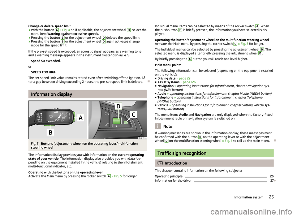
Fig. 5
Buttons (adjustment wheel) on the operating lever/multifunction
steering wheel
The information display provides you with information on the current operating
state of your vehicle . The information display also provides you with data (de-
pending on the equipment installed in the vehicle) relating to the Infotainment,
multi-functional indicator, etc.
Operating with the buttons on the operating lever
Activate the Main menu by pressing the rocker switch
A
» Fig. 5 for longer.
Individual menu items can be selected by means of the rocker switch A. When
the pushbutton B is briefly pressed, the information you have selected is dis-
played.
Operating the button/adjustment wheel on the multifunction steering wheel
Activate the Main menu by pressing the rocker switch C
» Fig. 5 for longer.
The individual menus can be selected by pressing the adjustment wheel
D
. The
selected menu is displayed after briefly pressing the adjustment wheel
D
.
By briefly pressing the
C
button you will reach one level higher.
Main menu points
The following information can be selected (depending on the equipment installed on the vehicle):
■ Driving data » page 22
■ Assist systems » page 126
■ Navigation » operating instructions for Infotainment , chapter Navigation sys-
tem (NAV button)
■ Audio » operating instructions for Infotainment , chapter Media (MEDIA button)
■ Telephone » operating instructions for Infotainment , chapter Telephone
(PHONE button)
■ Vehicle » operating instructions for Infotainment , chapter Setting vehicle sys-
tems (CAR button)
The menu items Audio and Navigation are only displayed when the factory-fitted
Infotainment radio or navigation system is switched on.
Note
If warning messages are shown in the information display, these messages must
be confirmed with the button B on the operating lever or with the adjustment
wheel D
on the multifunction steering wheel » Fig. 5 to call up the main menu.
Traffic sign recognition
Introduction
This chapter contains information on the following subjects:
Operating principle
26
Information for the driver
27
25Information system
Page 94 of 222
Starting-off and Driving
Starting and stopping the engine
Introduction
This chapter contains information on the following subjects:
Adjusting the steering wheel position
93
Power steering
93
Electronic immobiliser
93
Ignition lock
94
Starting engine
94
Switching the engine off
94
Starting and stopping the engine on vehicles with the KESSY system » page 95.
WARNING■
Never adjust the steering wheel when the vehicle is moving only when the
vehicle is stationary!■
Maintain a distance of 25 cm
1
to the steering wheel » Fig. 89 on page 93
– . Not maintaining this minimum distance will mean that the airbag system
will not be able to properly protect you – hazard!
■
The lever for adjusting the steering wheel must be locked whilst driving so
that the position of the steering wheel cannot accidently change during the journey – risk of accident!
■
If the steering wheel is adjusted further towards the head, the protection
provided by the driver airbag in the event of an accident is reduced. Check
that the steering wheel is aligned to the chest.
■
When driving, hold the steering wheel with both hands firmly on the outer
edge in the 9 o'clock and 3 o'clock position. Never hold the steering wheel in
the 12 o'clock position or in any other way (e.g. in the middle or inner edge of the steering wheel). In such cases, you could injure the arms, hands and head
when the driver airbag is deployed.
WARNING (Continued)■ When driving, the ignition key must always be in the position 2 » Fig. 90 on
page 94 (ignition switched on) without the engine running. This position is
indicated by the warning lights coming on. If this is not the case, it could result
in unexpected locking of the steering wheel – risk of accident!■
Only pull the ignition key from the ignition lock when the vehicle has come
to a complete stop (by applying the handbrake). Otherwise the steering wheel
could block – risk of accident!
■
When leaving the vehicle, the ignition must always be removed. This is par-
ticularly important if children are left in the vehicle. Otherwise the children
could, for example, start the engine – risk of accident or injury!
■
Never leave the engine running in unventilated or closed rooms. The ex-
haust gases of the engine contain besides the odorless and colourless carbon
monoxide a poisonous gas – hazard! Carbon monoxide can cause uncon-
sciousness and death.
■
Never leave the vehicle unattended with the engine running.
■
Never switch off the engine before the vehicle is stationary – risk of acci-
dent!
CAUTION
■ The starter may only be operated (ignition key position 3 » Fig. 90 on
page 94), if the engine is not running. The starter or engine can be damaged if
the starter is activated when the engine is running.■
Avoid high engine revolutions, full throttle and high engine loads as long as the
engine has not yet reached its operating temperature – risk of damaging the en-
gine!
■
Do not tow start the engine - danger of damaging the engine! On vehicles with
a catalytic converter, unburnt fuel may get into the catalytic converter where it
may ignite. This in turn may damage the catalytic converter. The battery from an- other vehicle can be used as a jump-start aid » page 195.
■
Do not switch the engine off immediately at the end of your journey after the
engine has been operated over a prolonged period at high loads but leave it to
run at an idling speed for about 1 minute. This prevents any possible accumulation of heat when the engine is switched off.
For the sake of the environment
Do not warm up the engine while the vehicle is stationary. If possible, start your
journey as soon as the engine has started. Through this the engine reaches its
operating temperature more rapidly and the pollutant emissions are lower. 92Using the system
Page 108 of 222
Towing a trailer
Towing device
Introduction
This chapter contains information on the following subjects:
Description
106
Setting the ready position
107
Installing the ball rod
107
Check proper attachment
108
Removing the ball rod
108
Operation and maintenance
109
If your vehicle has already been factory-fitted with a towing device or is fitted
with a towing device from ŠKODA Original Accessories, then it meets all of the
technical requirements and national legal provisions for towing a trailer.
Your vehicle is fitted with a 13-pin power socket for the electrical connection be-tween the vehicle and trailer. If the trailer that is to be towed has a 7-pin connec-
tor , you can use a suitable adapter from ŠKODA Original Accessories.
The maximum trailer drawbar load is 75 kg/h.
WARNING■
Before each time you make a journey when using the ball rod, check that it
is seated correctly and is secured in the mounting recess.■
Do not operate the ball rod if it is not correctly inserted in the mounting re-
cess.
■
Do not operate the towing device if it is damaged or incomplete.
■
Do not perform any modifications or changes to the towing device.
■
Never release the ball rod while the trailer is still coupled.
CAUTION
■ If there is an error in the trailer lighting system, check the fuses in the fuse box
in the dashboard. » page 200■
Handle the ball rod carefully to avoid damaging the paintwork on the bumper.
Note■
After coupling the trailer and connecting up the power socket, check the rear
lights on the trailer to ensure they work.■
If you have any questions, please contact a ŠKODA Partner.
Description
Fig. 99
Carrier of the towing device/ball rod
First read and observe the introductory information and safety warn-
ings
on page 106.
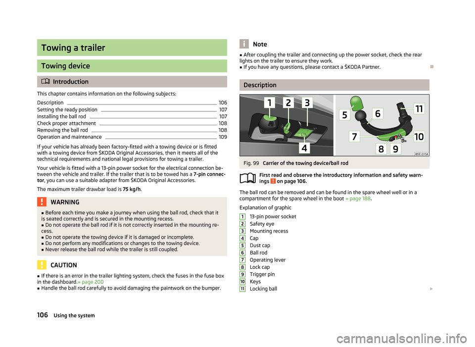
The ball rod can be removed and can be found in the spare wheel well or in a
compartment for the spare wheel in the boot » page 188.
Explanation of graphic
13-pin power socket
Safety eye
Mounting recess
Cap
Dust cap
Ball rod
Operating lever
Lock cap
Trigger pin
Keys
Locking ball
1234567891011106Using the system
Page 114 of 222
Assist systems
Brake assist systems
Introduction
This chapter contains information on the following subjects:
Stabilisation Control (ESC)
112
Antilock brake system (ABS)
113
Traction control system (TCS)
113
Electronic differential lock (EDL)
114WARNING■ A lack of fuel can cause irregular engine running or cause the engine to shut
down. The brake assist systems would then be without function – risk of acci-
dent!■
Adjust the speed and driving style to the current visibility, weather, road and
traffic conditions. The increased safety offered by the brake assist systems must not tempt you to take greater risks than otherwise – risk of an accident!
■
In the event of an ABS fault, visit a ŠKODA specialist garage immediately.
Adjust your style of driving according to the damage to the ABS as you will not know how great the damage is and the limitation it is placing on the braking
efficiency.
CAUTION
■ All four wheels must be fitted with the same tyres approved by the manufactur-
er to ensure the brake assist systems operate correctly.■
Changes to the vehicle (e.g. to the engine, brakes, chassis) can influence the
functionality of the brake assist systems » page 165.
Note
If a fault occurs in the ABS system, the ESC, ASR and EDL also do not work. An
ABS fault is indicated with the warning light » page 17 .
Stabilisation Control (ESC)Fig. 105
ESC system: TCS button
First read and observe the introductory information and safety warn-
ings on page 112.
The ESC system helps to maintain control of the vehicle in situations where it is
being operated at its dynamic limits, such as a sudden change to the direction of
travel. The risk of skidding is reduced and your car thus offers greater driving sta-
bility depending on the conditions of the road surface.
The ESC system is automatically activated each time the ignition is switched on.The direction which the driver wishes to take is determined based on the steering angle and the speed of the vehicle and is constantly compared with the actualbehaviour of the vehicle. If differences exist, such as the car beginning to skid,
the ESC system will automatically brake the appropriate wheel.
During an intervention of the system, the warning light
flashes in the instru-
ment cluster.
The following systems are integrated into the electronic stabilisation control
(ESC) :
› Antilock brake system (ABS),
› Traction control (TCS),
› Electronic differential lock (EDL)
› Active driver-steering recommendation (DSR),
› Brake assistant (HBA)
› Hill hold control (HHC);
› “Multicollision brake”;
› Trailer stabilisation (TSA)
» page 110, Driving with a trailer .
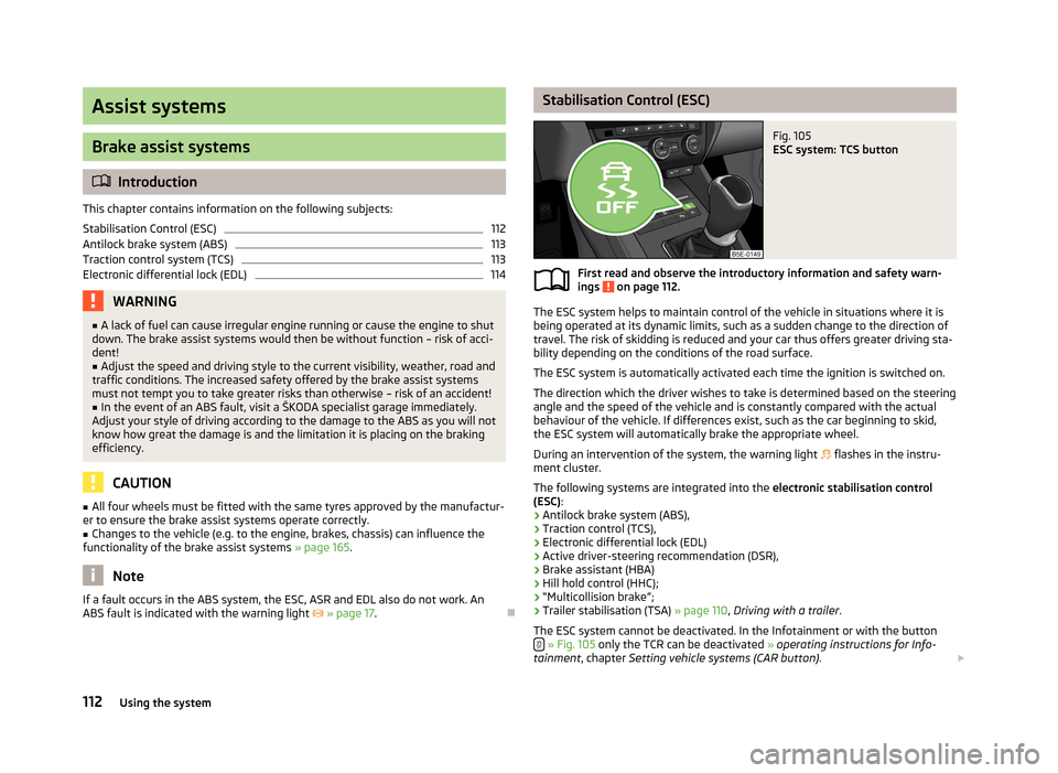
The ESC system cannot be deactivated. In the Infotainment or with the button
» Fig. 105 only the TCR can be deactivated » operating instructions for Info-
tainment , chapter Setting vehicle systems (CAR button) .
112Using the system
Page 119 of 222
finding a parking spaceFig. 109
System button (switch on the display in the instrument cluster dis-
play) /display: search for a suitable parking space for parallel or
perpen-
dicular parking
First read and observe the introductory information and safety warn- ings
on page 116.
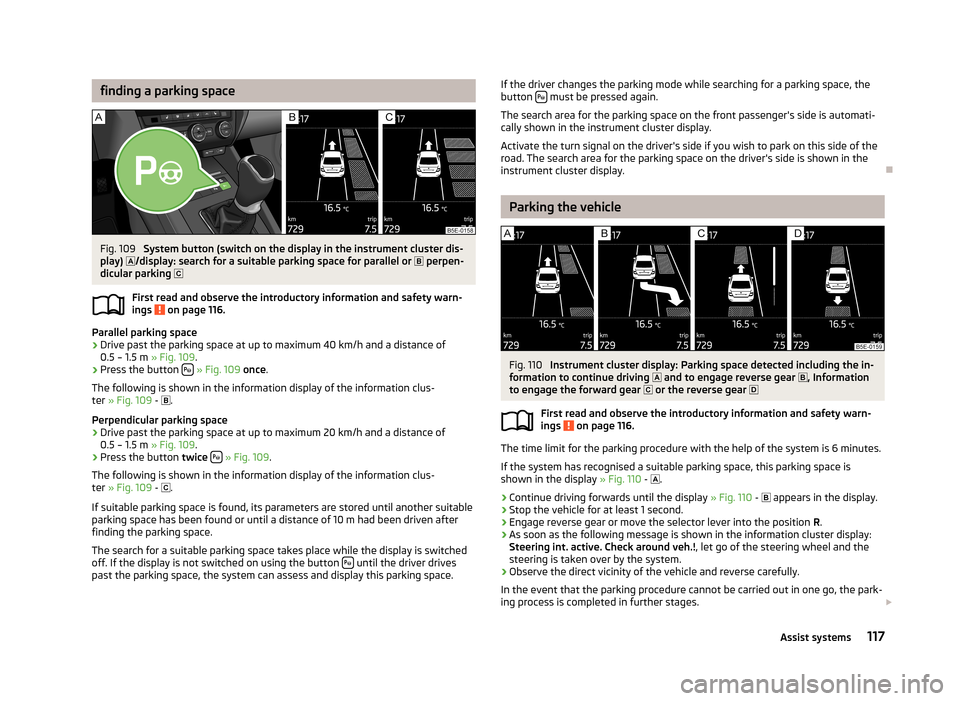
Parallel parking space
›
Drive past the parking space at up to maximum 40 km/h and a distance of 0.5 – 1.5 m » Fig. 109.
›
Press the button
» Fig. 109 once .
The following is shown in the information display of the information clus- ter » Fig. 109 -
.
Perpendicular parking space
›
Drive past the parking space at up to maximum 20 km/h and a distance of 0.5 – 1.5 m » Fig. 109.
›
Press the button twice
» Fig. 109 .
The following is shown in the information display of the information clus-
ter » Fig. 109 -
.
If suitable parking space is found, its parameters are stored until another suitable
parking space has been found or until a distance of 10 m had been driven after finding the parking space.
The search for a suitable parking space takes place while the display is switched
off. If the display is not switched on using the button
until the driver drives
past the parking space, the system can assess and display this parking space.
If the driver changes the parking mode while searching for a parking space, the
button must be pressed again.
The search area for the parking space on the front passenger's side is automati-
cally shown in the instrument cluster display.
Activate the turn signal on the driver's side if you wish to park on this side of the road. The search area for the parking space on the driver's side is shown in the
instrument cluster display.
Parking the vehicle
Fig. 110
Instrument cluster display: Parking space detected including the in-
formation to continue driving and to engage reverse gear
, Information
to engage the forward gear or the reverse gear
First read and observe the introductory information and safety warn- ings
on page 116.
The time limit for the parking procedure with the help of the system is 6 minutes.
If the system has recognised a suitable parking space, this parking space is
shown in the display » Fig. 110 -
.
›
Continue driving forwards until the display » Fig. 110 -
appears in the display.
›
Stop the vehicle for at least 1 second.
›
Engage reverse gear or move the selector lever into the position R.
›
As soon as the following message is shown in the information cluster display:
Steering int. active. Check around veh.! , let go of the steering wheel and the
steering is taken over by the system.
›
Observe the direct vicinity of the vehicle and reverse carefully.
In the event that the parking procedure cannot be carried out in one go, the park- ing process is completed in further stages.
117Assist systems
Page 137 of 222
INDUSTRY CANADA Statements
Le présent appareil est conforme aux CNR d'Industrie Canada applicables aux
appareils radio exempts de licence. L'exploitation est autorisée aux deux
conditions suivantes : (1) l'appareil ne doit pas produire de brouillage, et (2)
l'utilisateur de l'appareil doit accepter tout brouillage radioélectrique subi, même
si le brouillage est susceptible d'en compromettre le fonctionnement.
Phonebox
The vehicle body partially interferes with the telephone signal and makes use of
the mobile telephone somewhat more difficult in regions with a weak signal. The
current consumption and the telephone battery discharges more quickly.
To reduce the effects of these defects, an induction plate is located on the bot-
tom of the stowage compartment in the centre console » Fig. 68 on page 74. The
induction plate generates a induction field for the telephone signal which is direc- ted to the plate on the roof aerial where it is amplified.
The mobile phone kept in the stowage compartment with the underside on the
induction plate can use a signal boosted by around 20 %.
As a result:
› the sending and receiving power of the telephone is improved;
› the discharge of the phone battery is reduced;
› the electromagnetic radiation is reduced in the vehicle interior.
Multimedia
Operating Infotainment from the multifunction steering wheel
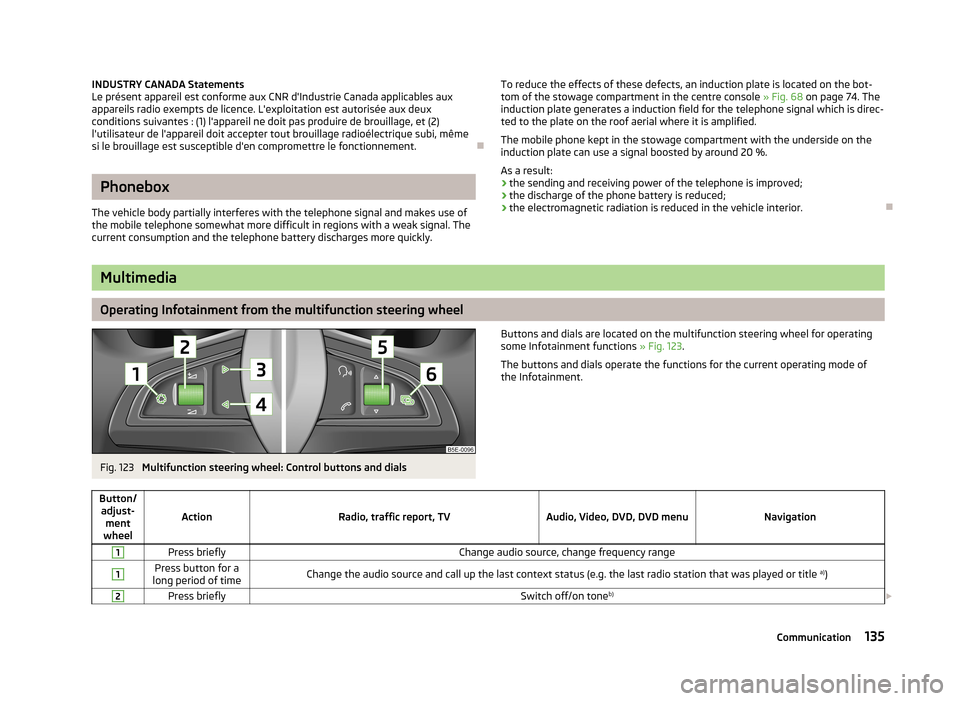
Fig. 123
Multifunction steering wheel: Control buttons and dials
Buttons and dials are located on the multifunction steering wheel for operating
some Infotainment functions » Fig. 123.
The buttons and dials operate the functions for the current operating mode of the Infotainment.Button/ adjust- ment
wheel
ActionRadio, traffic report, TVAudio, Video, DVD, DVD menuNavigation
1Press brieflyChange audio source, change frequency range1Press button for a
long period of timeChange the audio source and call up the last context status (e.g. the last radio station that was played or title a)
)2Press brieflySwitch off/on tone b)
135Communication
Page 138 of 222
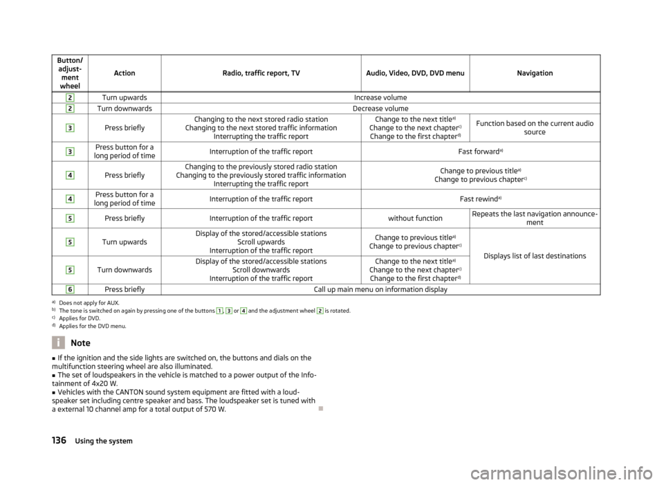
Button/adjust- ment
wheel
ActionRadio, traffic report, TVAudio, Video, DVD, DVD menuNavigation
2Turn upwardsIncrease volume2Turn downwardsDecrease volume3
Press brieflyChanging to the next stored radio station
Changing to the next stored traffic information Interrupting the traffic reportChange to the next title a)
Change to the next chapter c)
Change to the first chapter d)Function based on the current audio
source3Press button for a
long period of timeInterruption of the traffic reportFast forward a)4
Press brieflyChanging to the previously stored radio station
Changing to the previously stored traffic information Interrupting the traffic reportChange to previous title a)
Change to previous chapter c)4Press button for a
long period of timeInterruption of the traffic reportFast rewind a)5Press brieflyInterruption of the traffic reportwithout functionRepeats the last navigation announce-
ment5
Turn upwardsDisplay of the stored/accessible stationsScroll upwards
Interruption of the traffic reportChange to previous title a)
Change to previous chapter c)
Displays list of last destinations
5
Turn downwardsDisplay of the stored/accessible stations
Scroll downwards
Interruption of the traffic reportChange to the next title a)
Change to the next chapter c)
Change to the first chapter d)6Press brieflyCall up main menu on information displaya)
Does not apply for AUX.
b)
The tone is switched on again by pressing one of the buttons
1
,
3
or
4
and the adjustment wheel
2
is rotated.
c)
Applies for DVD.
d)
Applies for the DVD menu.
Note■
If the ignition and the side lights are switched on, the buttons and dials on the
multifunction steering wheel are also illuminated.■
The set of loudspeakers in the vehicle is matched to a power output of the Info-
tainment of 4x20 W.
■
Vehicles with the CANTON sound system equipment are fitted with a loud-
speaker set including centre speaker and bass. The loudspeaker set is tuned with
a external 10 channel amp for a total output of 570 W.
136Using the system