instrument cluster SKODA OCTAVIA 2013 3.G / (5E) Owner's Guide
[x] Cancel search | Manufacturer: SKODA, Model Year: 2013, Model line: OCTAVIA, Model: SKODA OCTAVIA 2013 3.G / (5E)Pages: 287, PDF Size: 18.55 MB
Page 118 of 287
Defrosting windscreenFirst read and observe the introductory information given on page 112.
Switching on/off
›
Press the symbol button » Fig. 110 on page 112.
›
Press the symbol button again or press the symbol button .
More air flows out of the air outlet vents 1 » Fig. 106 on page 107. The tempera-
ture control is controlled automatically.
Auxiliary heating (auxiliary heating and ventilation)
Introduction
This chapter contains information on the following subjects:
Switching on/off
116
Radio remote control
116
Conditions for the functioning of auxiliary heating (Aux. heating and ventilation),
hereinafter referred to only as auxiliary heating (Aux. heating).
The charge state of the vehicle battery is sufficient.
The fuel supply is adequate (the warning icon
is not lit in the display of the
instrument cluster).
Auxiliary ventilation
The auxiliary ventilation enables fresh air to flow into the vehicle interior by
switching off the engine, whereby the interior temperature is effectively de-
creased (e.g. with the vehicle parked in the sun).
Auxiliary heating (parking heating)
The auxiliary heating (parking heating) can be used when stationary, when the engine is switched off to preheat the vehicle and while driving (e.g. during the
heating phase of the engine).
The auxiliary heater (parking heater) functions in connection with the air-condi-
tioning system or Climatronic.
The auxiliary heating (parking heating) also warms up the engine.
The auxiliary heating (parking heating) warms up the coolant by combusting fuel
from the vehicle tank. The coolant heats air flowing into the passenger compart- ment (as long as the blower fan speed B
» Fig. 108 on page 108 or
C
» Fig. 110
on page 112 is not set to zero).
WARNING■ The auxiliary heater (independent vehicle heater) must never be operated in
closed rooms (e.g. garages) – risk of poisoning!■
The auxiliary heating (parking heating) must not be running during refuelling
– risk of fire.
■
The exhaust pipe of the auxiliary heating is located underneath the vehicle.
Therefore, if you wish to operate the auxiliary heating (parking heating), do
not park the vehicle in such a way that the exhaust gases can come into con-
tact with highly flammable materials (e.g. dry grass) or easily inflammable sub-
stances (e.g. spilt fuel) – risk of fire.
CAUTION
■ The running auxiliary heating (parking heating) consumes fuel from the vehicle
tank and automatically controls the filling level. If only a low quantity of fuel is
present in the fuel tank, the auxiliary heater switches itself off.■
The exhaust pipe of the auxiliary heating, which is located underneath the vehi-
cle, must not be clogged up and the exhaust flow must not be blocked.
■
If the auxiliary heating is running, the vehicle battery discharges. If the auxiliary
heating and ventilation has been operated several times over a longer period, the
vehicle must be driven a few kilometres in order to recharge the vehicle battery.
Note
■ The auxiliary heating (aux. heating) switches on the blower B » Fig. 108 on
page 108 or C » Fig. 110 on page 112 only if it has achieved a coolant temperature
of approx. 50 °C.■
At low outside temperatures, this can result in a formation of water vapour in
the area of the engine compartment. This is quite normal and is not an operating problem.
■
The air inlet in front of the windscreen must be free of e.g. ice, snow or leaves
to ensure that the auxiliary heating and cooling system operates properly.
■
So that warm air can flow into the vehicle interior after switching on the auxili-
ary heating, you must maintain the comfort temperature normally selected by
you, leave the fan switched on and leave the air outlet vents in an open position.
It is recommended to put the air flow in the position or .
115Heating and air-conditioning
Page 126 of 287
If the steering is still not unlocked, then the following message is displayed on
the display of the instrument cluster.
Move the steering wheel!
MOVE STEERING WHEEL
Slightly move the steering wheel and the system will make up to 3 more attempts
to unlock after 2 seconds. At the same time, the indicator light flashes.
If the steering is still not unlocked, to try to eliminate the possible cause and then
repeat the unlocking attempt.
Switching on the ignition
First read and observe the introductory information and safety warn-
ings
on page 121.
›
Press the starter button » Fig. 116 on page 122 briefly.
The ignition is switched on.
Note
The ignition is switched on when indicated by the lighting up of certain indicator
lamps in the instrument cluster.
Starting the engine
First read and observe the introductory information and safety warn-
ings
on page 121.
Vehicles with a diesel engine are equipped with a glow plug system. The glow
plug warning light
illuminates after the ignition has been switched on. Start
the engine after the warning light
has gone out.
You should not switch on any major electrical components during the heating pe- riod otherwise the vehicle battery will be drained unnecessarily.
Procedure for starting the engine
›
Firmly apply the handbrake.
›
Move the gearshift lever into neutral or move the selector lever into position P
or N.
›
Depress and hold the clutch pedal (vehicles with a manual gearbox) or brake
pedal (vehicles with an automatic gearbox) until the engine starts.
› Press the starter button
» Fig. 116 on page 122 briefly – the engine starts auto-
matically.›
Release the handbrake.
CAUTION
■ If the engine does not start up after a second attempt, one of the following
fuses may be defective. ■Petrol engine - fuse for the fuel pump.
■ Diesel engine - fuse for the glow plug control unit or fuel pump.■
Check the fuse and replace if necessary » page 251, or seek assistance from a
specialist garage.
Switching off the ignition
First read and observe the introductory information and safety warn-ings
on page 121.
›
Press the starter button » Fig. 116 on page 122 briefly.
The ignition is switched off.
The ignition can be switched off up to a speed of 2 km/h.
On vehicles fitted with a manual gearbox, the clutch pedal must not be de-
pressed after switching off the ignition, otherwise the system would try to start.
For automatic transmission vehicles, the brake pedal must not be depressed,
otherwise the system will try to start.
If the driver's door is opened while the igition is on, an audible signal sounds andthe following message appears in the instrument cluster display.
Ignition on!
IGNITION STILL ON
When leaving the vehicle always switch off the ignition.
Switching off the engine
First read and observe the introductory information and safety warn-ings
on page 121.
›
Stop the vehicle.
›
Press the starter button » Fig. 116 on page 122 .
123Starting-off and Driving
Page 127 of 287
The engine and the ignition are switched off simultaneously.
Emergency start-up of the engine
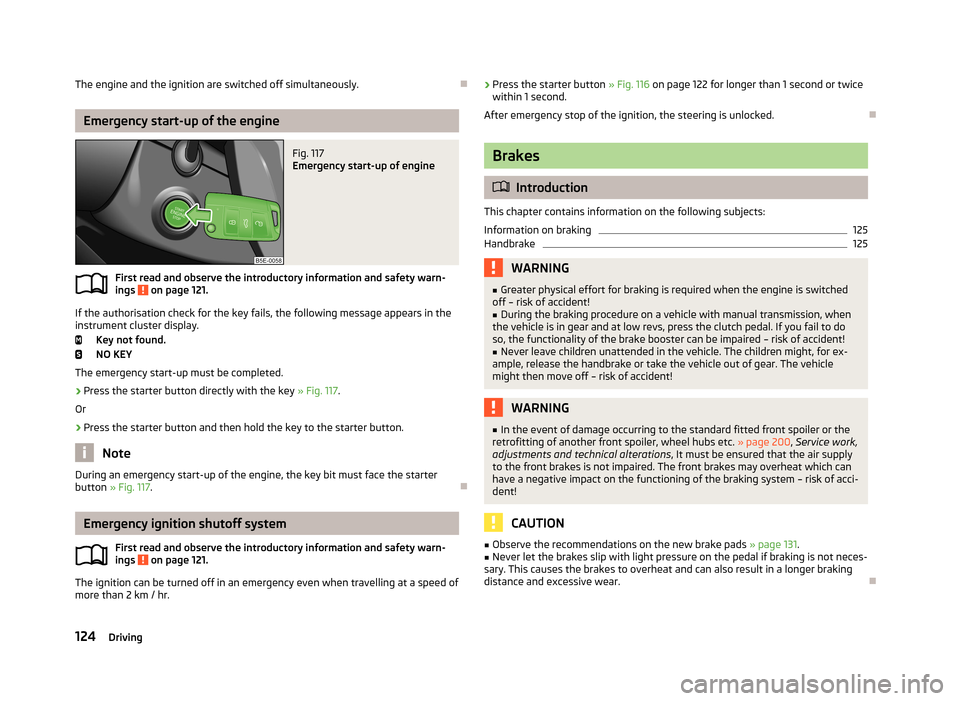
Fig. 117
Emergency start-up of engine
First read and observe the introductory information and safety warn-ings on page 121.
If the authorisation check for the key fails, the following message appears in the instrument cluster display.
Key not found.
NO KEY
The emergency start-up must be completed.
› Press the starter button directly with the key
» Fig. 117.
Or
› Press the starter button and then hold the key to the starter button.
Note
During an emergency start-up of the engine, the key bit must face the starter
button » Fig. 117 .
Emergency ignition shutoff system
First read and observe the introductory information and safety warn-
ings
on page 121.
The ignition can be turned off in an emergency even when travelling at a speed of
more than 2 km / hr.
› Press the starter button
» Fig. 116 on page 122 for longer than 1 second or twice
within 1 second.
After emergency stop of the ignition, the steering is unlocked.
Brakes
Introduction
This chapter contains information on the following subjects:
Information on braking
125
Handbrake
125WARNING■ Greater physical effort for braking is required when the engine is switched
off – risk of accident!■
During the braking procedure on a vehicle with manual transmission, when
the vehicle is in gear and at low revs, press the clutch pedal. If you fail to do
so, the functionality of the brake booster can be impaired – risk of accident!
■
Never leave children unattended in the vehicle. The children might, for ex-
ample, release the handbrake or take the vehicle out of gear. The vehicle might then move off – risk of accident!
WARNING■ In the event of damage occurring to the standard fitted front spoiler or the
retrofitting of another front spoiler, wheel hubs etc. » page 200, Service work,
adjustments and technical alterations , It must be ensured that the air supply
to the front brakes is not impaired. The front brakes may overheat which can
have a negative impact on the functioning of the braking system – risk of acci-
dent!
CAUTION
■ Observe the recommendations on the new brake pads » page 131.■Never let the brakes slip with light pressure on the pedal if braking is not neces-
sary. This causes the brakes to overheat and can also result in a longer braking
distance and excessive wear.
124Driving
Page 131 of 287
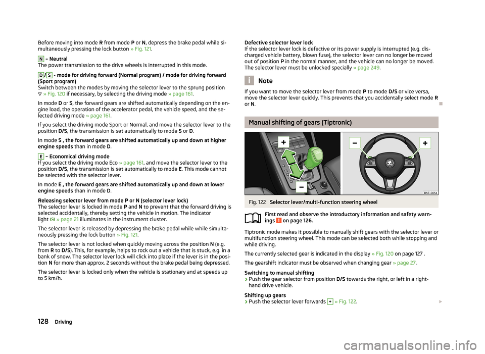
Before moving into mode R from mode P or N, depress the brake pedal while si-
multaneously pressing the lock button » Fig. 121.N
– Neutral
The power transmission to the drive wheels is interrupted in this mode.
D
/
S
- mode for driving forward (Normal program) / mode for driving forward
(Sport program)
Switch between the modes by moving the selector lever to the sprung position
» Fig. 120 if necessary, by selecting the driving mode » page 161.
In mode D or S, the forward gears are shifted automatically depending on the en-
gine load, the operation of the accelerator pedal, the vehicle speed, and the se-
lected driving mode » page 161.
If you select the driving mode Sport or Normal, and move the selector lever to the
position D/S, the transmission is set automatically to mode S or D.
In mode S , the forward gears are shifted automatically up and down at higher
engine speeds than in mode D.
E
– Economical driving mode
If you select the driving mode Eco » page 161, and move the selector lever to the
position D/S, the transmission is set automatically to mode E. This mode cannot
be selected with the selector lever.
In mode E , the forward gears are shifted automatically up and down at lower
engine speeds than in mode D.
Releasing selector lever from mode P or N (selector lever lock) The selector lever is locked in mode P and N to prevent that the forward driving is
selected accidentally, thereby setting the vehicle in motion. The indicator
light
» page 21 illuminates in the instrument cluster.
The selector lever is released by depressing the brake pedal while while simulta-
neously pressing the lock button » Fig. 121.
The selector lever is not locked when quickly moving across the position N (e.g.
from R to D/S ). This, for example, helps to rock out a vehicle that is stuck, e.g. in a
bank of snow. The selector lever lock will click into place if the lever is in the posi-
tion N for more than approx. 2 seconds without the brake pedal being depressed.
The selector lever is locked only when the vehicle is stationary and at speeds up
to 5 km/h.
Defective selector lever lock
If the selector lever lock is defective or its power supply is interrupted (e.g. dis-
charged vehicle battery, blown fuse), the selector lever can no longer be moved
out of position P in the normal manner, and the vehicle can no longer be moved.
The selector lever must be unlocked specially » page 249.
Note
If you want to move the selector lever from mode P to mode D/S or vice versa,
move the selector lever quickly. This prevents that you accidentally select mode R
or N.
Manual shifting of gears (Tiptronic)
Fig. 122
Selector lever/multi-function steering wheel
First read and observe the introductory information and safety warn- ings
on page 126.
Tiptronic mode makes it possible to manually shift gears with the selector lever or
multifunction steering wheel. This mode can be selected both while stopping and
while driving.
The currently selected gear is indicated in the display » Fig. 120 on page 127 .
The gearshift indicator must be observed when changing gear » page 27.
Switching to manual shifting
›
Push the gear selector from position D/S towards the right, or left in a right-
hand drive vehicle.
Shifting up gears
›
Push the selector lever forwards
+
» Fig. 122 .
128Driving
Page 141 of 287
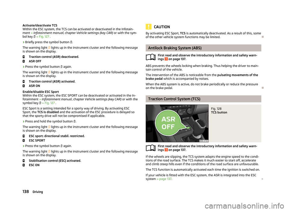
Activate/deactivate TCS
Within the ESC system, the TCS can be activated or deactivated in the Infotain-
ment » Infotainment manual , chapter Vehicle settings (key CAR) or with the sym-
bol key » Fig. 127 .
› Briefly press the symbol button
.
The warning light lights up in the instrument cluster and the following message
is shown on the display.
Traction control (ASR) deactivated.
ASR OFF
› Press the symbol button
again.
The warning light
lights up in the instrument cluster and the following message
is shown on the display.
Traction control (ASR) activated.ASR ON
Enable/disable ESC Sport Within the ESC system, the ESC SPORT can be deactivated or activated in the In-
fotainment » Infotainment manual , chapter Vehicle settings (key CAR) or with the
symbol key
» Fig. 127 .
ESC Sport is a setting intended for a sporty way of driving. By activating ESC
Sport, the TCS is disabled and the activation of the ESC procedure is delayed so
that the sporty drive will not be compromised if applicable.
› Press and hold the symbol button
.
The warning light
lights up in the instrument cluster and the following message
is shown on the display.
ESC sport: directional stabil. restricted.
ESC SPORT
› Press the symbol button
again.
The warning light
lights up in the instrument cluster and the following message
is shown on the display.
Stabilisation control (ESC) activated.
ESC ONCAUTIONBy activating ESC Sport, TCS is automatically deactivated. As a result of this, some
of the other vehicle system functions may be limited.
Antilock Braking System (ABS)
First read and observe the introductory information and safety warn-
ings
on page 137.
ABS prevents the wheels locking when braking. Thus helping the driver to main-
tain control of the vehicle.
The intervention of the ABS is noticeable from the pulsating movements of the
brake pedal which is accompanied by noises.
When the ABS system is active, do not brake periodically or reduce the pressure
on the brake pedal.
Traction Control System (TCS)
Fig. 128
TCS button
First read and observe the introductory information and safety warn- ings on page 137.
If the wheels are slipping, the TCS system adapts the engine speed to the condi-
tions of the road surface. The TCS makes it much easier to start off, accelerate
and climb steep hills even if the conditions of the road surface are unfavourable.
The TCS function is automatically activated each time the ignition is switched on.
If your vehicle is fitted with the ESC system, the ASR is integrated into the ESC
system » page 137 .
138Driving
Page 142 of 287
During an intervention of the system, the TCS warning light flashes in the in-
strument cluster.
The TCS should normally always be enabled. The system should be deactivated
only in the following situations, for example.
› When driving with snow chains.
› When driving in deep snow or on a very loose surface.
› When it is necessary to “rock” a car free when it has become stuck.
The TCS can be deactivated in the Infotainment or with the symbol button
» Fig. 128 » Infotainment manual , chapter Vehicle settings (CAR button) .
The warning light lights up in the instrument cluster when the TCR is deactiva-
ted.
Ensure the TCS is activated again afterwards.
Electronic Differential Lock (EDL and XDS)
First read and observe the introductory information and safety warn-
ings
on page 137.
EDL
If one of the wheels starts to spin, the EDL system brakes the spinning wheel and
transfers the driving force to the other wheels. This ensures the stability of the
vehicle and a quick journey.
The EDL switches itself off automatically, in order to avoid excessive heat genera-
tion in the disc brake of the wheel being braked. The vehicle can continue to be
driven and has the same characteristics as a vehicle not fitted with EDL. The EDL
switches on again automatically as soon as the brake has cooled down.
XDS
XDL is an extension to the electronic differential lock. XDL does not respond to traction, but to the load relief of the inner front wheel of the driving axle during
fast cornering.
The automatic brake intervention on the brake of the wheel with reduced load prevents the wheel from spinning. Thus, the traction is improved and the vehicle can continue to follow the desired track.
Driver Steering Recommendation (DSR)
First read and observe the introductory information and safety warn-ings
on page 137.
The DSR indicates to the driver in critical situations a steering recommendation in
order to stabilise the vehicle. The DSR is activated, for example, on the right and
left vehicle side when braking sharply on different road surfaces.
Hydraulic Brake Assist (HBA)
First read and observe the introductory information and safety warn-ings
on page 137.
HBA increases the braking effect and helps to shorten the braking distance.
The HBA is activated by the very quick operation of the brake pedal. To achieve
the shortest possible braking distance, the brake pedal must be applied firmly un-
til the vehicle has come to a complete standstill.
The HBA is automatically switched off when the brake pedal is released.The ABS is activated faster and more effectively with the intervention of the HBA.
Hill Hold Control (HHC)
First read and observe the introductory information and safety warn-ings
on page 137.
HHC allows you, when driving on slopes, to move your foot from the brake pedal
to the accelerator pedal without having to use the handbrake.
The system holds the brake pressure produced by the activation of the brakepedal for approx. 2 seconds after the brake pedal is released.
The brake pressure drops gradually the more you operate the accelerator pedal. Ifthe vehicle does not start off within 2 seconds, it starts to roll back.
The HHC is active from a 5% slope if the driver's door is closed. HHC is always ac-tive on slopes when in forward or reverse start off. When driving downhill, it is in- active.
139Assist systems
Page 149 of 287
The parking procedure was ended because TCS was deactivated during the park-
ing procedure.
Trailer: Park Assist stopped.
The parking procedure cannot be carried out because a trailer is hitched. Time limit exceeded. Take over steering!
The parking procedure was ended because the time limit of 6 minutes was passed.
Park Assist currently not available.
The system cannot be activated because a fault exists on the vehicle. Seek help
from a specialist garage.
Park Assist stopped. Not available.
The parking procedure was ended because a fault exists on the vehicle. Seek help
from a specialist garage.
Park Assist faulty. Workshop!
The parking procedure is not possible because a fault exists in the system. Seek help from a specialist garage.
ASR intervention. Take over steering!
The parking procedure is terminated by a TCS intervention. Park Assist: indicate and engage reverse
The prerequisites for manoeuvring out of a parking space using the system have
been met. Switch on the turn signals and shift into reverse.
Aut. parking space exit not possible. Space too small.
The manoeuvring procedure using the system is not possible. The parking gap is too small.
Braking intervention. Speed too high.
The driving speed during the parking procedure was too high - automatic brake
assist is initiated.Cruise Control System
Introduction
This chapter contains information on the following subjects:
Activating/deactivating
147
Storing and maintaining speed
147
Changing the stored speed
147
Switching off temporarily
147
Information on the display
148
The Cruise Control System (CCS) maintains a set speed, more than 25 km/h, with-
out you having to actuate the accelerator pedal.
This is only possible within the range which is permitted by the power output and
braking power of the engine.
The warning light
illuminates in the instrument cluster when the cruise control
system is switched on.
WARNING■ For safety reasons, the cruise control system must not be used in dense
traffic or on unfavourable road surfaces (such as icy roads, slippery roads,
loose gravel) – risk of accident!■
The saved speed may only be resumed if it is not too high for the current
traffic conditions.
■
Always deactivate the cruise control system after use to prevent uninten-
tional switching on of the system.
CAUTION
■ The cruise control system is not able to maintain a constant speed when driving
in areas with very steep gradients. The weight of the vehicle increases the speed
at which it travels. In such cases, a lower gear should be engaged or the foot-
brake applied.■
It is not possible to switch on the cruise control system if the first gear or re-
verse gear is engaged (Vehicles fitted with a manual transmission)
■
The cruise control system cannot be activated when the selector lever is in po-
sitions P, N or R (vehicles with automatic transmission).
146Driving
Page 151 of 287
Briefly push the rocker button B into the RES/+ position in order to resume the
stored speed after the clutch or brake pedal is released.
Information on the display
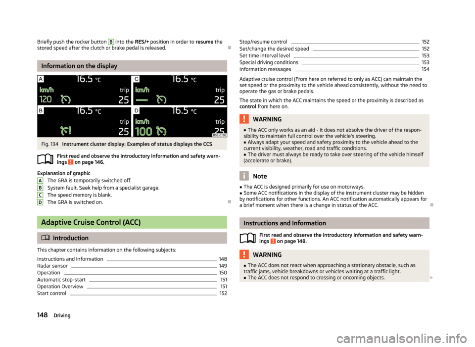
Fig. 134
Instrument cluster display: Examples of status displays the CCS
First read and observe the introductory information and safety warn- ings
on page 146.
Explanation of graphic
The GRA is temporarily switched off.
System fault. Seek help from a specialist garage.
The speed memory is blank. The GRA is switched on.
Adaptive Cruise Control (ACC)
Introduction
This chapter contains information on the following subjects:
Instructions and Information
148
Radar sensor
149
Operation
150
Automatic stop-start
151
Operation Overview
151
Start control
152ABCDStop/resume control152Set/change the desired speed152
Set time interval level
153
Special driving conditions
153
Information messages
154
Adaptive cruise control (From here on referred to only as ACC) can maintain the
set speed or the proximity to the vehicle ahead consistently, without the need to
operate the gas or brake pedals.
The state in which the ACC maintains the speed or the proximity is described as
control from here on.
WARNING■
The ACC only works as an aid - it does not absolve the driver of the respon-
sibility to maintain full control over the vehicle's steering.■
Always adapt your speed and safety proximity to the vehicle ahead to the
current visibility, weather, road and traffic conditions.
■
The driver must always be ready to take over steering of the vehicle himself
(accelerate or brake).
Note
■ The ACC is designed primarily for use on motorways.■Some ACC notifications in the display of the instrument cluster may be hidden
by notifications for other functions. An ACC notification automatically appears for
a brief moment when there is a change in status of the ACC.
Instructions and Information
First read and observe the introductory information and safety warn-ings
on page 148.
WARNING■ The ACC does not react when approaching a stationary obstacle, such as
traffic jams, vehicle breakdowns or vehicles waiting at a traffic light.■
The ACC does not respond to crossing or oncoming objects. 148Driving
Page 152 of 287
WARNING (Continued)■If the ACC does not decelerate fast enough, immediately apply the vehicle's
footbrake.■
Control may only be resumed if the stored speed is not too high for the cur-
rent traffic conditions.
WARNINGFor safety reasons, do not use the ACC under the following conditions.■When driving in turning lanes, motorway exits or construction sites, to avoid
an unwanted acceleration to the stored speed.■
When visibility is poor, (e.g. fog, heavy rain, thick snowfall).
■
When road conditions are poor (e.g. ice, slippery road, gravel, dirt road).
■
When driving around “sharp” bends.
■
When riding on a steep gradient / high slope.
CAUTION
■ It is not possible to switch on the control on vehicles fitted with a manual
transmission if the first gear or reverse gear is engaged.■
It is not possible to switch on the control on vehicles fitted with an automatic
transmission , if the selector lever is in the position P, N or R .
■
The control may automatically switch off when some brake assist systems (e.g.
ESC) intervene, when the maximum permissible engine speed is exceeded, etc.
Note
■ The speed can only be set and stored when ACC is activated. The stored speed
may differ from the actual speed if a proximity control procedure is in progress at the time.■
Vehicles with an automatic transmission can decelerate to a standstill and start
again using the ACC.
■
The ACC reduces the speed by automatically releasing the accelerator or by
means of a braking procedure as appropriate. If the brakes are used for an auto-
matic speed reduction at any moments, then the brake light illuminates.
■
In case of failure of more than one brake light on the vehicle or on the electri-
cally connected trailer, the ACC becomes unavailable.
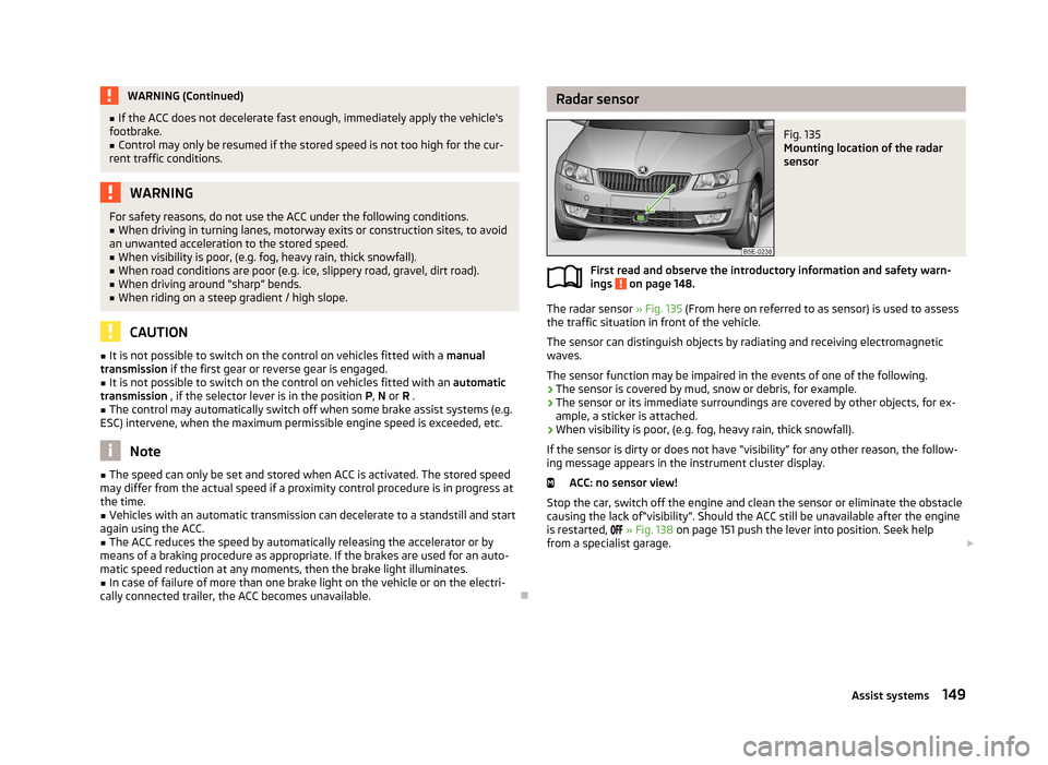
Radar sensorFig. 135
Mounting location of the radar
sensor
First read and observe the introductory information and safety warn-
ings on page 148.
The radar sensor » Fig. 135 (From here on referred to as sensor) is used to assess
the traffic situation in front of the vehicle.
The sensor can distinguish objects by radiating and receiving electromagneticwaves.
The sensor function may be impaired in the events of one of the following.
› The sensor is covered by mud, snow or debris, for example.
› The sensor or its immediate surroundings are covered by other objects, for ex-
ample, a sticker is attached.
› When visibility is poor, (e.g. fog, heavy rain, thick snowfall).
If the sensor is dirty or does not have “visibility” for any other reason, the follow- ing message appears in the instrument cluster display.
ACC: no sensor view!
Stop the car, switch off the engine and clean the sensor or eliminate the obstacle
causing the lack of“visibility”. Should the ACC still be unavailable after the engine is restarted,
» Fig. 138 on page 151 push the lever into position. Seek help
from a specialist garage.
149Assist systems
Page 153 of 287
WARNING■If you suspect that the sensor is damaged, deactivate the ACC. Have the
sensor checked by a specialist garage.■
The sensor can become misaligned by collisions or by damage to the front of
the vehicle, the wheel arch or the underside of the vehicle. This can lead to an
impairment of the ACC function - risk of accidents! If this is the case, have the
sensor checked by a specialist garage.
■
Any improperly carried out work to the front of the vehicle may cause the
sensor to become misaligned. We therefore recommend only having these
modifications and technical alterations carried out by a specialist garage.
Please also observed the instructions in » page 200, Service work, adjust-
ments and technical alterations .
■
The area in front of and around the sensor must not be covered with stick-
ers, additional lights or similar items. This can lead to impaired function of the sensor - risk of accidents!
CAUTION
The sensor may not be able to distinguish all objects correctly under certain cir-cumstances. We therefore recommend that you avoid using the ACC in the follow-
ing cases.■
When driving through places where metal objects (such as metal buildings, rail-
road tracks, etc.) can be found.
■
When driving through very divided and enclosed spaces (such as large-capacity
garages, car ferries, tunnels and the like.).
CAUTION
Remove the snow with a brush and the ice with a solvent-free de-icer.
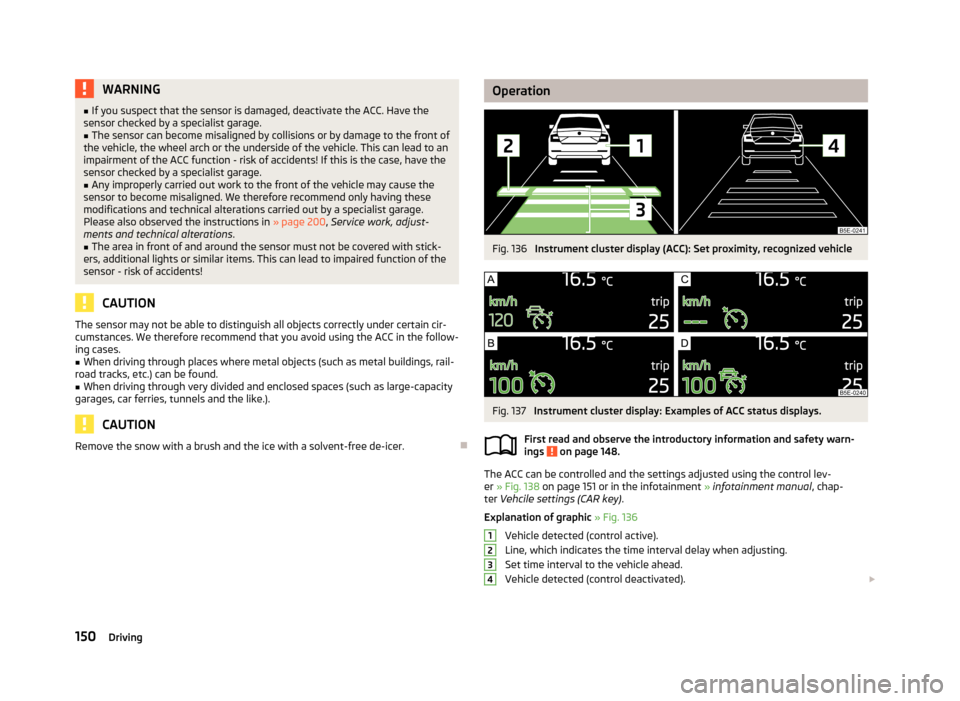
OperationFig. 136
Instrument cluster display (ACC): Set proximity, recognized vehicle
Fig. 137
Instrument cluster display: Examples of ACC status displays.
First read and observe the introductory information and safety warn-
ings
on page 148.
The ACC can be controlled and the settings adjusted using the control lev-
er » Fig. 138 on page 151 or in the infotainment » infotainment manual , chap-
ter Vehcile settings (CAR key) .
Explanation of graphic » Fig. 136
Vehicle detected (control active).
Line, which indicates the time interval delay when adjusting. Set time interval to the vehicle ahead.
Vehicle detected (control deactivated).
1234150Driving