sensor SKODA OCTAVIA 2014 3.G / (5E) User Guide
[x] Cancel search | Manufacturer: SKODA, Model Year: 2014, Model line: OCTAVIA, Model: SKODA OCTAVIA 2014 3.G / (5E)Pages: 280, PDF Size: 35.53 MB
Page 80 of 280
Only the rear fog light on the trailer lights up if the vehicle has a factory-fitted
towing device or a towing device from ŠKODA original accessories and it is
driven with a trailer.
COMING HOME / LEAVING HOME
Read and observe
on page 71 first.
COMING HOME (hereinafter referred to only as a function) switches the light
automatically for a short time after leaving the vehicle.
LEAVING HOME (hereinafter referred to only as a function) switches the light
automatically for a short time when approaching the vehicle.
The daytime running lights are switched on automatically if the following
conditions are met.
The light switch is in position
» Fig. 52 on page 73 .
The visibility in the vehicle environment is reduced.
The ignition is switched off.
The parking aid is activated.
The function is switched on (the driver's door is opened/the car is un-
locked via the remote control).
The function switches on the following light, depending on the equipment
fitted.
› Parking lights
› Low beam
› Entry lighting in the exterior mirrors
› Licence plate light
Poorer visibility is evaluated by a sensor mounted in the bracket of the interior
mirror.
COMING HOME
The light turns on automatically when you open the driver's door on (within 60
seconds of turning off the ignition).
The light turns off 10 seconds after closing all the doors and the boot lid or af-
ter the pre-set time has expired.
If a door or the boot lid remains open, the light goes out after 60 seconds.
LEAVING HOME
The light turns on automatically after the vehicle is unlocked with the remote
control.
The light turns off after 10 seconds or after a pre-set time or after the vehicle
is locked.
Enabling / disabling and setting function
The functions and setting of the lighting duration can be activated or deactiva-
ted in the Infotainment » Operating instructions for Infotainment , chapter Ve-
hicle settings (button CAR) .
CAUTION
■
Do not attach any stickers or similar objects in front of the light sensor on
the windscreen to avoid impairing the function or its reliability.■
If this function is activated constantly, the battery will be heavily discharged
particularly in short-haul traffic.
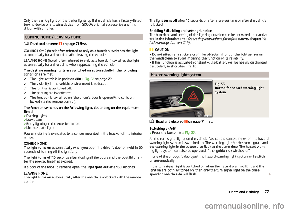
Hazard warning light system
Fig. 55
Button for hazard warning light
system
Read and observe on page 71 first.
Switching on/off
›
Press the button
» Fig. 55 .
All the turn signal lights on the vehicle flash at the same time when the hazard
warning light system is switched on. The warning light for the turn signals and
the warning light in the button also flash at the same time. The hazard warn-
ing light system can also be operated if the ignition is switched off.
If one of the airbags is deployed, the hazard warning light system will switch
on automatically.
If the turn signal light is switched on when the hazard warning light and the
ignition are both switched on, then only the turn signal light on the corre-
sponding vehicle side will flash.
77Lights and visibility
Page 87 of 280

WARNING■Make sure that the mirror is not covered by ice, snow, mist or other ob-
jects.■
Convex (curved outward) or aspheric exterior mirrors increase the field of
vision. They do, however, make objects appear smaller in the mirror. These
mirrors are therefore only of limited use for estimating distances to the fol-
lowing vehicles.
■
Whenever possible use the interior mirror for estimating the distances to
the following vehicles.
WARNINGThe mirrors with automatic dimming contain an electrolyte liquid which can
escape if mirror glass is broken.■
The leaking electrolytic fluid can irritate the skin, eyes and breath appara-
tus. Immediately seek out fresh air and leave the vehicle. If this is not pos-
sible, at least open the window.
■
If you swallow electrolytic fluid, seek medical assistance immediately.
■
If your eyes or skin come into contact with the electrolytic fluid, immedi-
ately wash the affected area for a few minutes long with a lot of water.
Then consult a doctor immediately.
Interior mirror
Fig. 64
Interior mirror: manual dimming/auto-dimming/light sensor
Read and observe
on page 84 first.
Mirror with manual dimming » Fig. 64
Basic position of the mirror
Mirror blackout
12Mirror with automatic dimming » Fig. 64
Warning light - lights when dimming is activated
Switch for the activation of the automatic mirror dimming
Light sensor
Light sensor on the back of the mirror
Mirror with automatic dimming
If the automatic dimming is enabled, the mirror dims automatically depending
on the light falling on the sensors.
When the interior lights are switched on or the reverse gear is engaged, the
mirror always moves back into the basic position (not dimmed).
Do not attach external navigation devices on to the windscreen or in the vicini-
ty of the interior mirror »
.
WARNINGThe illuminated display of an external navigation unit can lead to opera-
tional faults to the automatic dimming interior mirror – risk of accident.
CAUTION
The automatic dimming mirror only functions smoothly if the light falling on
the sensors is not impaired, e.g. by the rear sun roller blind.
Note
If the automatic interior mirror dimming is switched off, the exterior mirror
dimming is also switched off.ABCD84Using the system
Page 121 of 280
Automatic activation/deactivation of the air recirculation
Climatronic may have an air quality sensor for the detection of the pollutant
concentration in the sucked-in air.
If a considerable increase in concentration of pollutants is recognised by the
air quality sensor, the recirculated air mode will be switched on automatically.
When the pollutant concentration decreases to the normal level, the recircula-
ted air mode is automatically switched off.
The automatic activation/deactivation of the air recirculation can be activated or deactivated in the Infotainment » Infotainment operating instructions ,
chapter Vehicle settings .WARNINGThe recirculation system cannot be switched on for a longer period of time,
because there is no supply of fresh air from the outside. “Stale air” may re-
sult in fatigue in the driver and occupants, reduce attention levels and also
cause the windows to mist up. The risk of having an accident increases.
Switch off recirculated air mode as soon as the windows start to mist up.
CAUTION
We recommend not smoking in the vehicle when the recirculating air operation
is switched on. The smoke sucked from inside the vehicle is deposited on the
evaporator of the air conditioner. This produces a permanent odour when the
air conditioning system is operating which can only be eliminated through con-
siderable effort and expense (replacement of compressor).
Note
The automatic activation/deactivation of the air recirculation with Climatronic
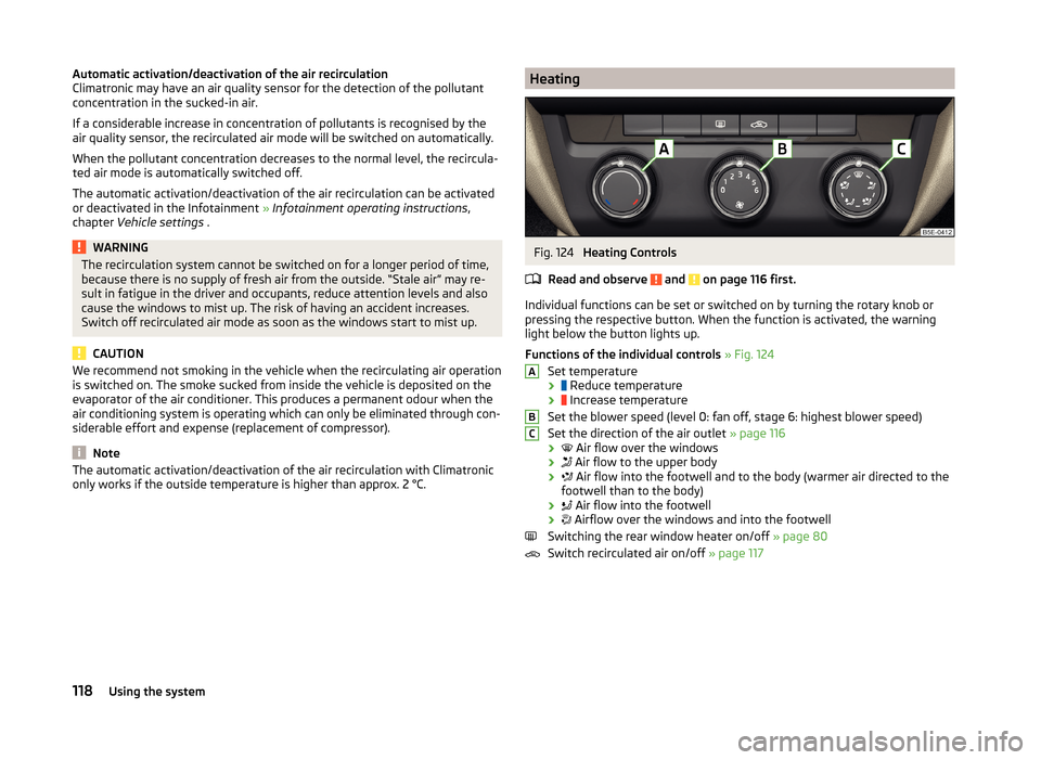
only works if the outside temperature is higher than approx. 2 °C.HeatingFig. 124
Heating Controls
Read and observe
and on page 116 first.
Individual functions can be set or switched on by turning the rotary knob or
pressing the respective button. When the function is activated, the warning
light below the button lights up.
Functions of the individual controls » Fig. 124
Set temperature ›
Reduce temperature
›
Increase temperature
Set the blower speed (level 0: fan off, stage 6: highest blower speed)
Set the direction of the air outlet » page 116
›
Air flow over the windows
›
Air flow to the upper body
›
Air flow into the footwell and to the body (warmer air directed to the
footwell than to the body)
›
Air flow into the footwell
›
Airflow over the windows and into the footwell
Switching the rear window heater on/off » page 80
Switch recirculated air on/off » page 117
ABC118Using the system
Page 122 of 280
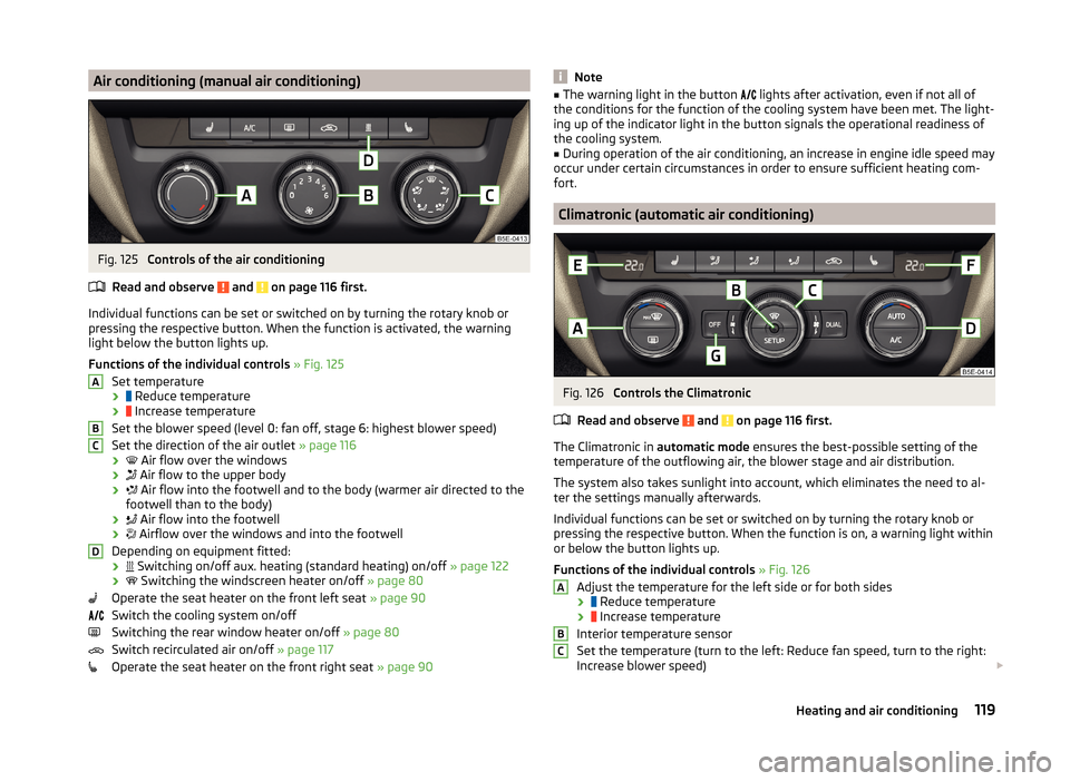
Air conditioning (manual air conditioning)Fig. 125
Controls of the air conditioning
Read and observe
and on page 116 first.
Individual functions can be set or switched on by turning the rotary knob or
pressing the respective button. When the function is activated, the warning
light below the button lights up.
Functions of the individual controls » Fig. 125
Set temperature ›
Reduce temperature
›
Increase temperature
Set the blower speed (level 0: fan off, stage 6: highest blower speed)
Set the direction of the air outlet » page 116
›
Air flow over the windows
›
Air flow to the upper body
›
Air flow into the footwell and to the body (warmer air directed to the
footwell than to the body)
›
Air flow into the footwell
›
Airflow over the windows and into the footwell
Depending on equipment fitted: ›
Switching on/off aux. heating (standard heating) on/off
» page 122
›
Switching the windscreen heater on/off
» page 80
Operate the seat heater on the front left seat » page 90
Switch the cooling system on/off
Switching the rear window heater on/off » page 80
Switch recirculated air on/off » page 117
Operate the seat heater on the front right seat » page 90
ABCDNote■
The warning light in the button lights after activation, even if not all of
the conditions for the function of the cooling system have been met. The light-
ing up of the indicator light in the button signals the operational readiness of
the cooling system.■
During operation of the air conditioning, an increase in engine idle speed may
occur under certain circumstances in order to ensure sufficient heating com-
fort.
Climatronic (automatic air conditioning)
Fig. 126
Controls the Climatronic
Read and observe
and on page 116 first.
The Climatronic in automatic mode ensures the best-possible setting of the
temperature of the outflowing air, the blower stage and air distribution.
The system also takes sunlight into account, which eliminates the need to al-
ter the settings manually afterwards.
Individual functions can be set or switched on by turning the rotary knob or
pressing the respective button. When the function is on, a warning light within
or below the button lights up.
Functions of the individual controls » Fig. 126
Adjust the temperature for the left side or for both sides
›
Reduce temperature
›
Increase temperature
Interior temperature sensor
Set the temperature (turn to the left: Reduce fan speed, turn to the right:
Increase blower speed)
ABC119Heating and air conditioning
Page 123 of 280
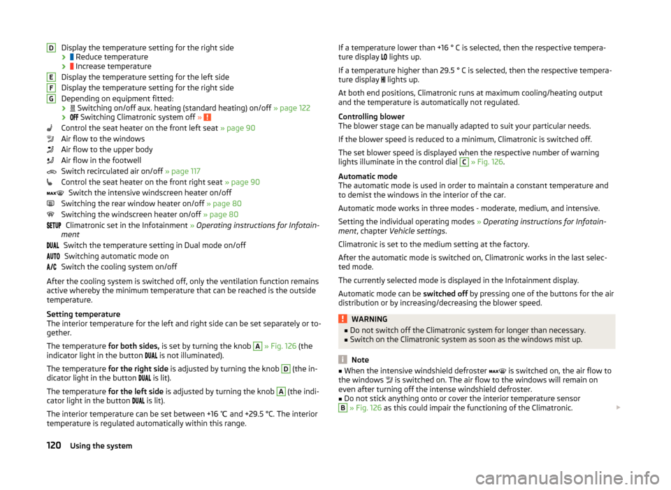
Display the temperature setting for the right side
›
Reduce temperature
›
Increase temperature
Display the temperature setting for the left side
Display the temperature setting for the right side
Depending on equipment fitted: ›
Switching on/off aux. heating (standard heating) on/off » page 122
›
Switching Climatronic system off »
Control the seat heater on the front left seat » page 90
Air flow to the windows
Air flow to the upper body
Air flow in the footwell
Switch recirculated air on/off » page 117
Control the seat heater on the front right seat » page 90
Switch the intensive windscreen heater on/off
Switching the rear window heater on/off » page 80
Switching the windscreen heater on/off » page 80
Climatronic set in the Infotainment » Operating instructions for Infotain-
ment
Switch the temperature setting in Dual mode on/offSwitching automatic mode on
Switch the cooling system on/off
After the cooling system is switched off, only the ventilation function remains active whereby the minimum temperature that can be reached is the outside
temperature.
Setting temperature
The interior temperature for the left and right side can be set separately or to-
gether.
The temperature for both sides, is set by turning the knob
A
» Fig. 126 (the
indicator light in the button is not illuminated).
The temperature for the right side is adjusted by turning the knob
D
(the in-
dicator light in the button is lit).
The temperature for the left side is adjusted by turning the knob
A
(the indi-
cator light in the button is lit).
The interior temperature can be set between +16 ℃ and +29.5 °C. The interior
temperature is regulated automatically within this range.
DEFGIf a temperature lower than +16 ° C is selected, then the respective tempera-
ture display lights up.
If a temperature higher than 29.5 ° C is selected, then the respective tempera-
ture display
lights up.
At both end positions, Climatronic runs at maximum cooling/heating output
and the temperature is automatically not regulated.
Controlling blower
The blower stage can be manually adapted to suit your particular needs.
If the blower speed is reduced to a minimum, Climatronic is switched off.
The set blower speed is displayed when the respective number of warning
lights illuminate in the control dial C
» Fig. 126 .
Automatic mode
The automatic mode is used in order to maintain a constant temperature and
to demist the windows in the interior of the car.
Automatic mode works in three modes - moderate, medium, and intensive.
Setting the individual operating modes » Operating instructions for Infotain-
ment , chapter Vehicle settings .
Climatronic is set to the medium setting at the factory.
After the automatic mode is switched on, Climatronic works in the last selec-
ted mode.
The currently selected mode is displayed in the Infotainment display.
Automatic mode can be switched off by pressing one of the buttons for the air
distribution or by increasing/decreasing the blower speed.
WARNING■ Do not switch off the Climatronic system for longer than necessary.■Switch on the Climatronic system as soon as the windows mist up.
Note
■When the intensive windshield defroster is switched on, the air flow to
the windows is switched on. The air flow to the windows will remain on
even after turning off the intense windshield defroster.■
Do not stick anything onto or cover the interior temperature sensor
B
» Fig. 126 as this could impair the functioning of the Climatronic.
120Using the system
Page 143 of 280
Hydraulic Brake Assist (HBA)Read and observe
on page 138 first.
HBA increases the braking effect and helps to shorten the braking distance.
The HBA is activated by the very quick operation of the brake pedal. To ach-
ieve the shortest possible braking distance, the brake pedal must be applied
firmly until the vehicle has come to a complete standstill.
The HBA is automatically switched off when the brake pedal is released.
Hill Hold Control (HHC)
Read and observe
on page 138 first.
HHC allows you, when driving on slopes, to move your foot from the brake
pedal to the accelerator pedal without having to use the handbrake.
The system holds the brake pressure produced by the activation of the brake pedal for approx. 2 seconds after the brake pedal is released.
The brake pressure drops gradually the more you operate the accelerator ped-
al. If the vehicle does not start off within 2 seconds, it starts to roll back.
The HHC is active from a 5% slope if the driver's door is closed. HHC is always active on slopes when in forward or reverse start off.
Multi-collision brake (MCB)
Read and observe
on page 138 first.
The MCB helps to decrease speed after a collision through automatic braking
interventions and to stabilize the vehicle. This reduces the risk of a subse-
quent crash due to uncontrolled vehicle movement.
The automatic brake interventions can take place only if the following condi-
tions are met.
A head-on or side collision occurred.
The impact speed was higher than approx. 10 km/h.
The brakes, the ESL and other required electrical systems remain function-
al after impact.
The accelerator pedal is not actuated.
Trailer stabilisation (TSA)
Read and observe
on page 138 first.
The TSA helps the combination stable in situations where the trailer sways
and then the whole trailer combination.
TSA brakes the individual wheels of the towing vehicle in order to damp the
rocking motion of the entire vehicle combination.
The following conditions are required for the correct TSA function. The trailer was shipped from the factory or purchased from the ŠKODA
genuine accessories.
The trailer is electrically connected to the towing vehicle by means of the
trailer socket.
The parking aid is activated.
The speed is higher than approx. 60 km/h.
The activated TSA is shown by the fact that after switching on the ignition, the
indicator light in the instrument cluster lights up for about 2 seconds longer
than the indicator light .
Further information » page 169, Hitch and trailer .
Parking aid
Introduction
This chapter contains information on the following subjects:
Function
141
Activation/deactivation
142
Road display
142
Automatic system activation when moving forward
143
The parking aid (hereinafter referred to only as system) draws attention via
acoustic signals or the Infotainment display when manoeuvring around obsta-
cles in the vicinity of the vehicle.
The system uses ultrasound waves to calculate the distance between the
bumper and an obstacle. Depending on the vehicle equipment, the ultrasonic
sensors are located in the back or in the front bumper » Fig. 139 on page 141 .
140Driving
Page 144 of 280
WARNING■The system only serves to support and does not relieve the driver of the
responsibility for the vehicle operation.■
Moving persons or objects may not be recognized by the system sensors.
■
Under certain circumstances, surfaces of certain objects and types of
clothing cannot reflect the system signals. For this reason, such people or
objects may not be recognised by the system sensors.
■
External noise sources may affect the signals of the system sensors. Un-
der adverse conditions, this may cause objects or people not to be recog-
nised by the system.
■
You should satisfy yourself before reversing that there is no small obsta-
cle, such as a rock, thin post, trailer drawbar etc., in front or behind your ve-
hicle. Such obstacles may not be recognised by the system sensors.
CAUTION
■ Keep the system sensors » Fig. 139 on page 141 clean, and free from snow
and ice, and do not cover with any objects of any kind, otherwise the system
functioning may be limited.■
Under adverse weather conditions (heavy rain, water vapour, very low or
high temperatures etc.), the system functioning may be limited - “incorrect ob-
stacle detection”.
■
Additionally installed accessories such as bicycle carriers can impair the sys-
tem functioning.
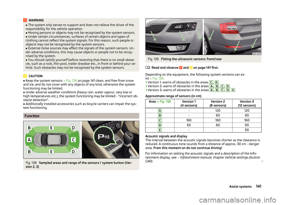
Function
Fig. 138
Sampled areas and range of the sensors / system button (Ver-
sion 2, 3)
Fig. 139
Fitting the ultrasonic sensors: front/rear
Read and observe
and on page 141 first.
Depending on the equipment, the following system versions can ex-
ist » Fig. 138 .
› Version 1: warns of obstacles in the areas
C
,
D
.
› Version 2: warns of obstacles in the areas
A
,
B
,
C
,
D
.
› Version 3: warns of obstacles in the areas
A
,
B
,
C
,
D
,
E
.
Approximate range of sensors (in cm)
Area » Fig. 138Version 1
(4 sensors)Version 2
(8 sensors)Version 3
(12 sensors)A-120120B-6090C160160160D606090E--90
Acoustic signals and display
The interval between the acoustic signals becomes shorter as the clearance is
reduced. A continuous tone sounds from a distance of approx. 30 cm - danger
area. From this moment on do not continue driving!
For information on setting the acoustic signals and a description of the Info-
tainment display, see » Infotainment manual , chapter Vehicle settings (button
CAR) .
141Assist systems
Page 146 of 280
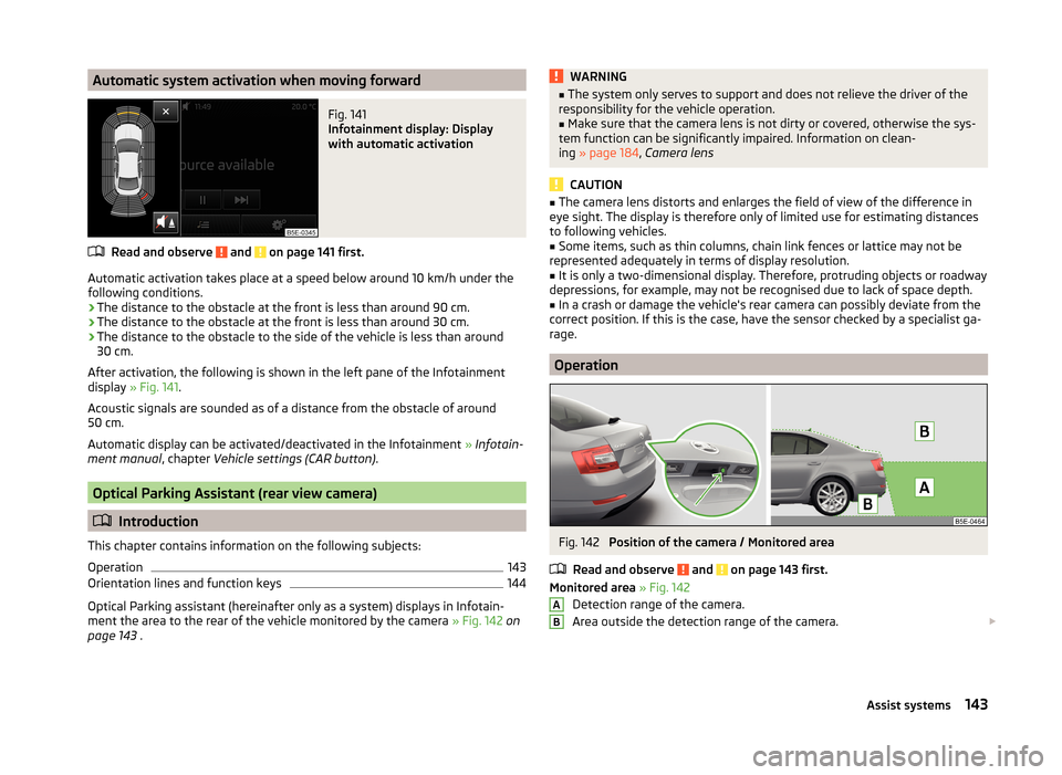
Automatic system activation when moving forwardFig. 141
Infotainment display: Display
with automatic activation
Read and observe and on page 141 first.
Automatic activation takes place at a speed below around 10 km/h under the following conditions.
› The distance to the obstacle at the front is less than around 90 cm.
› The distance to the obstacle at the front is less than around 30 cm.
› The distance to the obstacle to the side of the vehicle is less than around
30 cm.
After activation, the following is shown in the left pane of the Infotainment
display » Fig. 141 .
Acoustic signals are sounded as of a distance from the obstacle of around
50 cm.
Automatic display can be activated/deactivated in the Infotainment » Infotain-
ment manual , chapter Vehicle settings (CAR button) .
Optical Parking Assistant (rear view camera)
Introduction
This chapter contains information on the following subjects:
Operation
143
Orientation lines and function keys
144
Optical Parking assistant (hereinafter only as a system) displays in Infotain-
ment the area to the rear of the vehicle monitored by the camera » Fig. 142 on
page 143 .
WARNING■
The system only serves to support and does not relieve the driver of the
responsibility for the vehicle operation.■
Make sure that the camera lens is not dirty or covered, otherwise the sys-
tem function can be significantly impaired. Information on clean-
ing » page 184 , Camera lens
CAUTION
■
The camera lens distorts and enlarges the field of view of the difference in
eye sight. The display is therefore only of limited use for estimating distances
to following vehicles.■
Some items, such as thin columns, chain link fences or lattice may not be
represented adequately in terms of display resolution.
■
It is only a two-dimensional display. Therefore, protruding objects or roadway
depressions, for example, may not be recognised due to lack of space depth.
■
In a crash or damage the vehicle's rear camera can possibly deviate from the
correct position. If this is the case, have the sensor checked by a specialist ga-
rage.
Operation
Fig. 142
Position of the camera / Monitored area
Read and observe
and on page 143 first.
Monitored area » Fig. 142
Detection range of the camera.
Area outside the detection range of the camera.
AB143Assist systems
Page 148 of 280
The state in which the steering wheel is operated by the system, is referred to
as parking operation.
The parking aid is part of the park assist system, therefore the information
and safety guidelines » page 140 , Parking aid must also be read and ob-
served.WARNING■ The system only serves to support and does not relieve the driver of the
responsibility for the vehicle operation.■
During the parking process, the system automatically performs rapid
steering movements. While it is doing so, do not place your hands between
the steering wheel – risk of injury!
■
During a parking manoeuvre on loose or slippery surfaces (gravel, snow,
ice, etc.) you may stray from the calculated road because of the surface
conditions. Therefore we suggest that you do not use the system in such
situations.
■
External noise sources may affect the signals of the system sensors. Un-
der adverse conditions, this may cause objects or people to not be recog-
nised by the system.
CAUTION
■ If other vehicles are parked behind the kerb or on it, the system can also
guide your vehicle beyond the kerb or onto it. Ensure that the wheels or the
wheel rims of your vehicle are not damaged and if necessary intervene in time.■
Under certain circumstances, surfaces or structures of certain objects such
as wire mesh fences or powder snow cannot be recognised by the system.
■
Under adverse weather conditions (heavy rain, water vapour, very low or
high temperatures etc.), the system functioning may be limited - “incorrect ob-
stacle detection”.
CAUTION
The correct evaluation of the parking space and the parking procedure de-
pends on the circumference of the wheels on the vehicle.■
The system only works correctly if the vehicle is fitted with the wheel size
approved by the manufacturer.
■
Do without the use of the system if snow chains or a spare wheel is moun-
ted.
■
If wheels other than those approved by the manufacturer are mounted, the
resulting position of the vehicle in the parking space can differ slightly. This
can be avoided by readjusting the system at a specialist garage.
NoteWe recommend performing the parking at a safe speed to about 5 km / h.
Functioning
Read and observe
and on page 145 first.
Basic system operations
› The measurement and evaluation of the size of parking spaces when driving.
› The determination of the correct position of the vehicle for parking.
› The calculation of the line on which the vehicle drives backwards into the
parking space or forwards from the parking space.
› Automatic rotation of the front wheels during the parking.
The display of the instrument cluster (hereinafter only in the display) informa- tion and system messages are displayed.
When the system is activated, the warning light lights up
» Fig. 144 on
page 145 -
.
The traction control system (TCS) must always be switched on when parking.
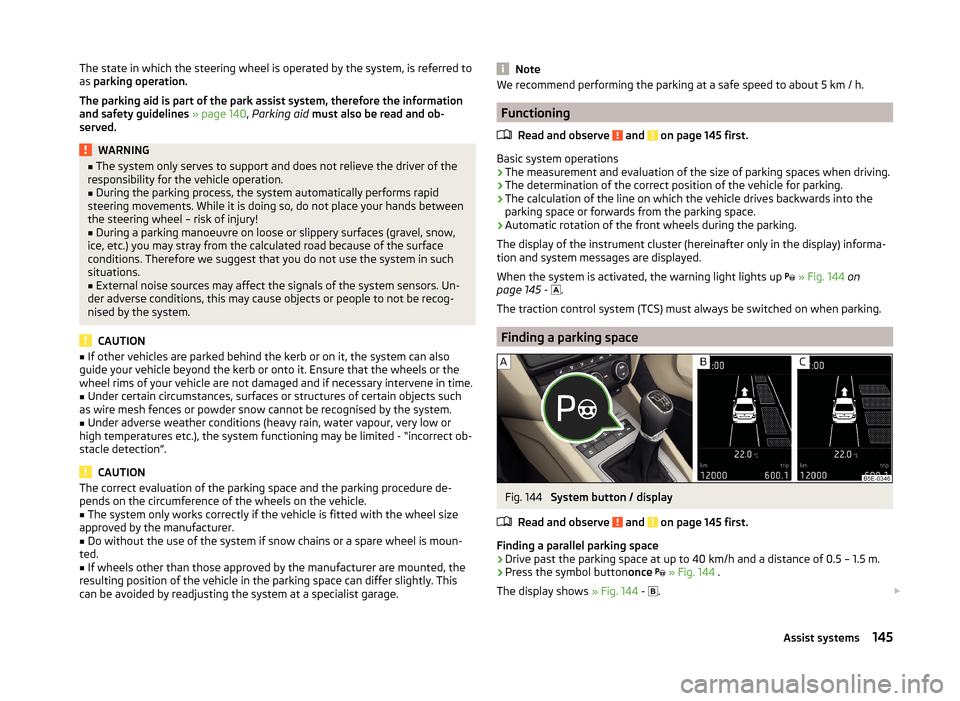
Finding a parking space
Fig. 144
System button / display
Read and observe
and on page 145 first.
Finding a parallel parking space
›
Drive past the parking space at up to 40 km/h and a distance of 0.5 – 1.5 m.
›
Press the symbol button once
» Fig. 144 .
The display shows » Fig. 144 -
.
145Assist systems
Page 152 of 280
This is only possible within the range which is permitted by the power output
and braking power of the engine.WARNINGIf the engine power or engine braking effect is insufficient to maintain the
set speed, the driver must take control of vehicle operation.
Operating Description
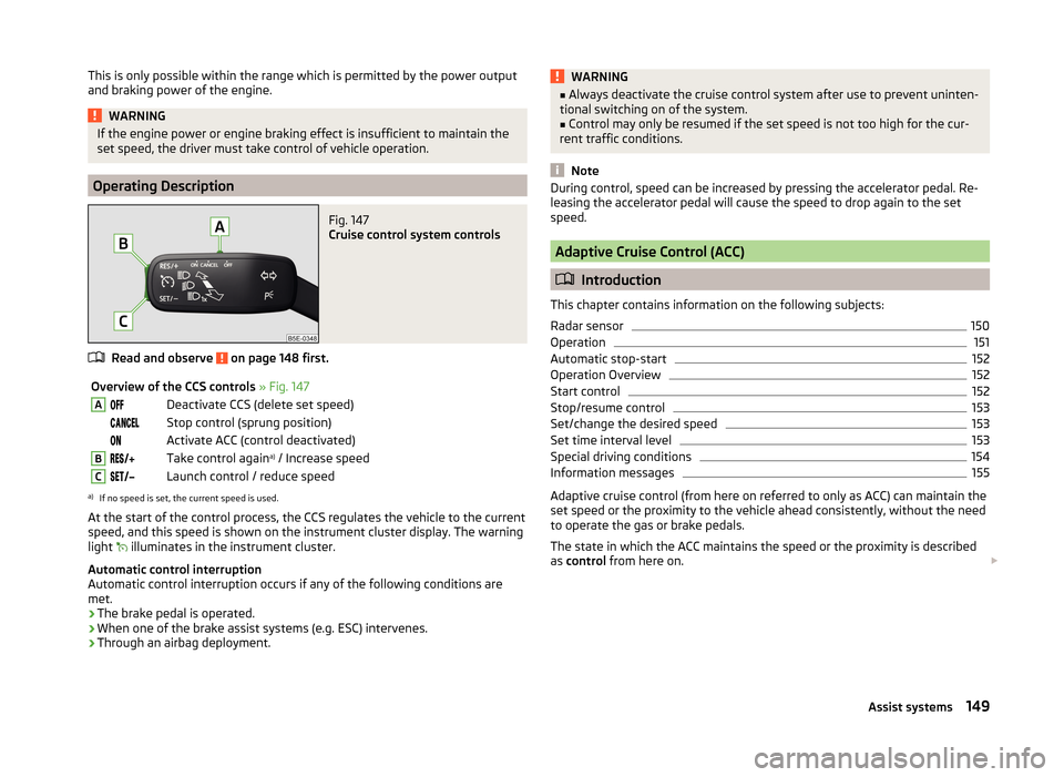
Fig. 147
Cruise control system controls
Read and observe on page 148 first.
Overview of the CCS controls » Fig. 147ADeactivate CCS (delete set speed) Stop control (sprung position) Activate ACC (control deactivated)BTake control again a)
/ Increase speedCLaunch control / reduce speeda)
If no speed is set, the current speed is used.
At the start of the control process, the CCS regulates the vehicle to the current
speed, and this speed is shown on the instrument cluster display. The warning
light illuminates in the instrument cluster.
Automatic control interruption
Automatic control interruption occurs if any of the following conditions are
met.
› The brake pedal is operated.
› When one of the brake assist systems (e.g. ESC) intervenes.
› Through an airbag deployment.
WARNING■
Always deactivate the cruise control system after use to prevent uninten-
tional switching on of the system.■
Control may only be resumed if the set speed is not too high for the cur-
rent traffic conditions.
Note
During control, speed can be increased by pressing the accelerator pedal. Re-
leasing the accelerator pedal will cause the speed to drop again to the set
speed.
Adaptive Cruise Control (ACC)
Introduction
This chapter contains information on the following subjects:
Radar sensor
150
Operation
151
Automatic stop-start
152
Operation Overview
152
Start control
152
Stop/resume control
153
Set/change the desired speed
153
Set time interval level
153
Special driving conditions
154
Information messages
155
Adaptive cruise control (from here on referred to only as ACC) can maintain the
set speed or the proximity to the vehicle ahead consistently, without the need
to operate the gas or brake pedals.
The state in which the ACC maintains the speed or the proximity is described
as control from here on.
149Assist systems