change time SKODA OCTAVIA 2014 3.G / (5E) Owner's Guide
[x] Cancel search | Manufacturer: SKODA, Model Year: 2014, Model line: OCTAVIA, Model: SKODA OCTAVIA 2014 3.G / (5E)Pages: 280, PDF Size: 35.53 MB
Page 202 of 280
CAUTION■Only refill with new coolant.■Do not use an alternative additive if the specified coolant is not available. In
this case, use just water and have the correct mixing ratio of water and cool-
ant additive restored by a specialist garage as soon as possible.
Brake fluid
Introduction
This chapter contains information on the following subjects:
Checking the brake fluid level
199
Specification
199
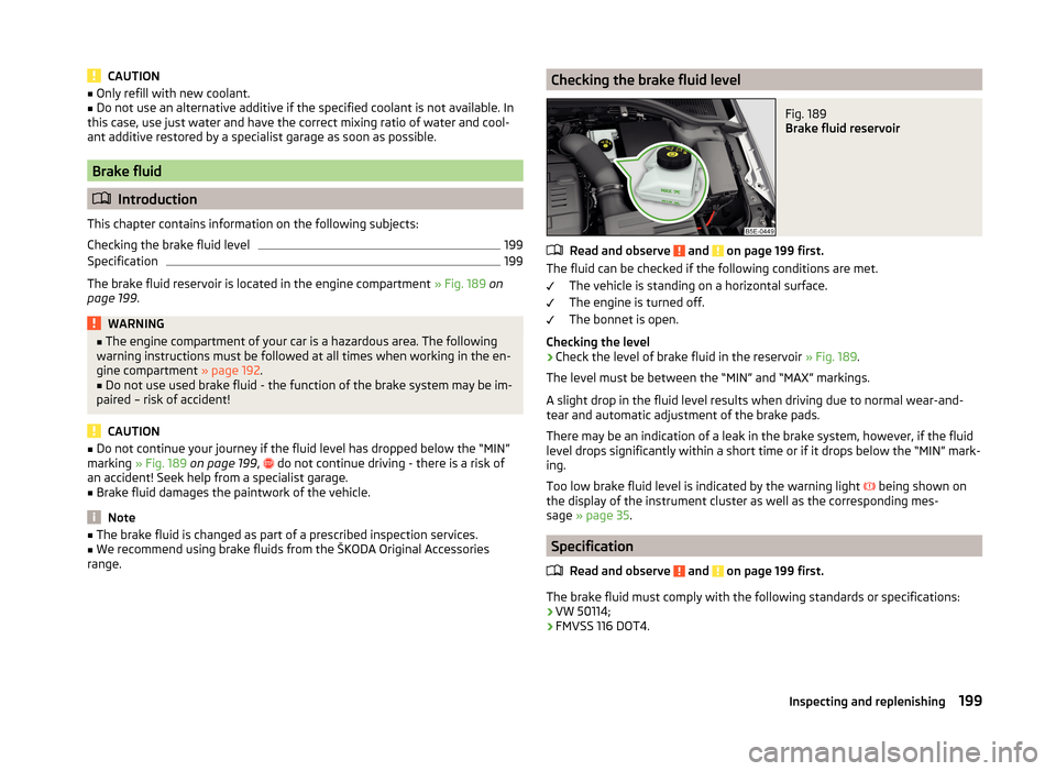
The brake fluid reservoir is located in the engine compartment » Fig. 189 on
page 199 .
WARNING■
The engine compartment of your car is a hazardous area. The following
warning instructions must be followed at all times when working in the en-
gine compartment » page 192.■
Do not use used brake fluid - the function of the brake system may be im-
paired – risk of accident!
CAUTION
■ Do not continue your journey if the fluid level has dropped below the “MIN”
marking » Fig. 189 on page 199 , do not continue driving - there is a risk of
an accident! Seek help from a specialist garage.■
Brake fluid damages the paintwork of the vehicle.
Note
■ The brake fluid is changed as part of a prescribed inspection services.■We recommend using brake fluids from the ŠKODA Original Accessories
range.Checking the brake fluid levelFig. 189
Brake fluid reservoir
Read and observe and on page 199 first.
The fluid can be checked if the following conditions are met.
The vehicle is standing on a horizontal surface.
The engine is turned off.
The bonnet is open.
Checking the level
›
Check the level of brake fluid in the reservoir » Fig. 189.
The level must be between the “MIN” and “MAX” markings.
A slight drop in the fluid level results when driving due to normal wear-and-
tear and automatic adjustment of the brake pads.
There may be an indication of a leak in the brake system, however, if the fluid
level drops significantly within a short time or if it drops below the “MIN” mark-
ing.
Too low brake fluid level is indicated by the warning light being shown on
the display of the instrument cluster as well as the corresponding mes-
sage » page 35 .
Specification
Read and observe
and on page 199 first.
The brake fluid must comply with the following standards or specifications:› VW 50114;
› FMVSS 116 DOT4.
199Inspecting and replenishing
Page 204 of 280

■Do not place the battery in direct daylight in order to protect the vehicle bat-
tery housing from the effects of ultra-violet light.■
If the vehicle is frequently used for making short trips, the vehicle battery
will not have time to charge up sufficiently and may discharge.
For the sake of the environment
A vehicle battery that has been removed is a special type of hazardous waste.
These must be disposed of in accordance with national legal regulations.
Note
■ We recommend having all work on the vehicle battery carried out by a spe-
cialist garage.■
You should replace batteries older than 5 years.
Opening the cover
Fig. 190
Polyester cover of vehicle bat-
tery
Read and observe and on page 200 first.
The battery is located in the engine compartment. For some equipment var-
iants, it is located underneath a polyester cover » Fig. 190.
›
Fold out the cover on the battery in the direction of the arrow.
The battery cover is installed in reverse order.
Checking the battery electrolyte levelFig. 191
Vehicle battery: Electrolyte level
indicator
Read and observe and on page 200 first.
On vehicles with a vehicle battery fitted with a colour indicator » Fig. 191, the
electrolyte level can be determined by looking at the change in colour of this
display.
Air bubbles can influence the colour of the indicator. For this reason carefully
knock on the indicator before carrying out the check.
› Black colour – electrolyte level is correct.
› Colourless or light yellow colour – electrolyte level too low, the battery must
be replaced.
Vehicles with a START-STOP system are fitted with a battery control unit for
checking the energy level for the recurring engine start.
We recommend that you have the acid level checked regularly by a specialist
garage, especially in the following cases.
› High external temperatures.
› Longer day trips.
› After each charge.
Winter time
The vehicle battery only has a proportion of the starting power in lower tem-
peratures. A discharged vehicle battery may already freeze at temperatures
just below 0 °C .
We therefore recommend that you have the battery checked and, if necessary,
recharged by a specialist garage before the start of the winter.
201Inspecting and replenishing
Page 208 of 280
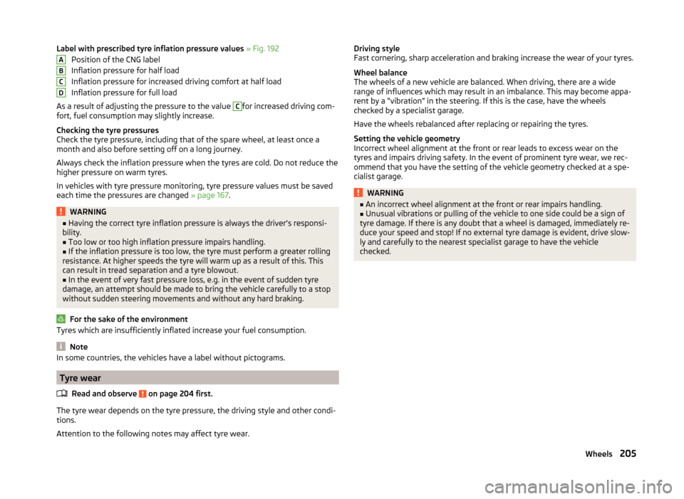
Label with prescribed tyre inflation pressure values » Fig. 192
Position of the CNG label
Inflation pressure for half load
Inflation pressure for increased driving comfort at half load
Inflation pressure for full load
As a result of adjusting the pressure to the value C
for increased driving com-
fort, fuel consumption may slightly increase.
Checking the tyre pressures
Check the tyre pressure, including that of the spare wheel, at least once a
month and also before setting off on a long journey.
Always check the inflation pressure when the tyres are cold. Do not reduce the
higher pressure on warm tyres.
In vehicles with tyre pressure monitoring, tyre pressure values must be saved
each time the pressures are changed » page 167.
WARNING■
Having the correct tyre inflation pressure is always the driver's responsi-
bility.■
Too low or too high inflation pressure impairs handling.
■
If the inflation pressure is too low, the tyre must perform a greater rolling
resistance. At higher speeds the tyre will warm up as a result of this. This
can result in tread separation and a tyre blowout.
■
In the event of very fast pressure loss, e.g. in the event of sudden tyre
damage, an attempt should be made to bring the vehicle carefully to a stop
without sudden steering movements and without any hard braking.
For the sake of the environment
Tyres which are insufficiently inflated increase your fuel consumption.
Note
In some countries, the vehicles have a label without pictograms.
Tyre wear
Read and observe
on page 204 first.
The tyre wear depends on the tyre pressure, the driving style and other condi-
tions.
Attention to the following notes may affect tyre wear.
ABCDDriving style
Fast cornering, sharp acceleration and braking increase the wear of your tyres.
Wheel balance
The wheels of a new vehicle are balanced. When driving, there are a wide
range of influences which may result in an imbalance. This may become appa-
rent by a “vibration” in the steering. If this is the case, have the wheels
checked by a specialist garage.
Have the wheels rebalanced after replacing or repairing the tyres.
Setting the vehicle geometry
Incorrect wheel alignment at the front or rear leads to excess wear on the
tyres and impairs driving safety. In the event of prominent tyre wear, we rec-
ommend that you have the setting of the vehicle geometry checked at a spe-
cialist garage.WARNING■ An incorrect wheel alignment at the front or rear impairs handling.■Unusual vibrations or pulling of the vehicle to one side could be a sign of
tyre damage. If there is any doubt that a wheel is damaged, immediately re-
duce your speed and stop! If no external tyre damage is evident, drive slow-
ly and carefully to the nearest specialist garage to have the vehicle
checked.205Wheels
Page 227 of 280
Towing the vehicle using the towing device is a viable alternative solution to
using the towing eye.
If the towing device is removed completely, it must be replaced with the
standard reinforcement of the rear bumper which is part of the mount for the
towing eye.
If this procedure is not observed, the vehicle may not meet the national legal
provisions.
CAUTION
The detachable ball rod and/or the vehicle can be damaged if an unsuitable
tow bar is used.
Note
The detachable ball rod must always be in the vehicle so that it can be used for
towing, if necessary.
Remote control
Introduction
This chapter contains information on the following subjects:
Replacing the battery in the remote control key
224
Synchronising the remote control
224
replace battery in the remote control the auxiliary heating (auxiliary
heating)
225
CAUTION
■ The replacement battery must have the same specification as the original
battery.■
We recommend having faulty rechargeable batteries replaced by a ŠKODA
service partner.
■
Pay attention to the correct polarity when changing the battery.
For the sake of the environment
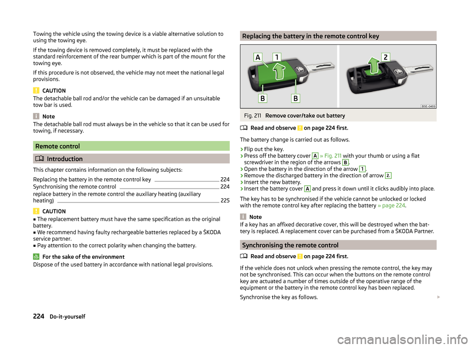
Dispose of the used battery in accordance with national legal provisions.Replacing the battery in the remote control keyFig. 211
Remove cover/take out battery
Read and observe
on page 224 first.
The battery change is carried out as follows.
›
Flip out the key.
›
Press off the battery cover
A
» Fig. 211 with your thumb or using a flat
screwdriver in the region of the arrows
B
.
›
Open the battery in the direction of the arrow
1
.
›
Remove the discharged battery in the direction of arrow
2.›
Insert the new battery.
›
Insert the battery cover
A
and press it down until it clicks audibly into place.
The key has to be synchronised if the vehicle cannot be unlocked or locked
with the remote control key after replacing the battery » page 224.
Note
If a key has an affixed decorative cover, this will be destroyed when the bat-
tery is replaced. A replacement cover can be purchased from a ŠKODA Partner.
Synchronising the remote control
Read and observe
on page 224 first.
If the vehicle does not unlock when pressing the remote control, the key may
not be synchronised. This can occur when the buttons on the remote control
key are actuated a number of times outside of the operative range of the
equipment or the battery in the remote control key has been replaced.
Synchronise the key as follows.
224Do-it-yourself
Page 235 of 280
Change bulb for long-distance, daytime running lights and parking light
switch233
Change bulb for additional parking light
233
Change bulb for fog light switch - Variant 1
234
Change bulb for fog light switch - Variant 2
234
Replacing the bulb for the licence plate light
235
Rear Light
235
Replacing bulbs in the rear light - Variant 1
236
Replacing bulbs in the rear light - Variant 2
237
Some manual skills are required to change a bulb. For this reason, we recom-
mend having bulbs replaced by a specialist garage or seeking other expert help
in the event of any uncertainties.
› Switch off the ignition and all of the lights before replacing a bulb.
› Faulty bulbs must only be replaced with the same type of bulbs. The designa-
tion is located on the light socket or the glass bulb.
› A stowage compartment for replacement bulbs is located in a plastic box in
the spare wheel or underneath the floor covering in the luggage compart-
ment.
WARNING■ Always read and observe the warnings before completing any work in the
engine compartment » page 192.■
Accidents can be caused if the road in front of the vehicle is not suffi-
ciently illuminated and the vehicle cannot or can only be seen with difficul-
ty by other road users.
■
Bulbs H7 H8 and H15 are pressurised and may burst when changing the
bulb - risk of injury! We therefore recommended wearing gloves and safety
glasses when changing a bulb.
■
Gas discharge bulbs (xenon bulbs) operate with a high voltage, professio-
nal knowledge is required – risk of death!
■
Switch off the respective vehicle light when changing the bulb.
CAUTION
Do not take hold of the glass bulb with naked fingers (even the smallest
amount of dirt reduces the working life of the light bulb). Use a clean cloth,
napkin, or similar.Note■ This Owner's Manual only describes the replacement of bulbs where it is pos-
sible to replace the bulbs on your own without any complications arising. Other
bulbs must be replaced by a specialist garage.■
We recommend that a box of replacement bulbs always be carried in the ve-
hicle. Replacement bulbs can be purchased from ŠKODAOriginal Accessories.
■
We recommend having the headlight settings checked by a specialist garage
after replacing a bulb in the main beam, low beam or fog lights.
■
In case of failure of a xenon gas discharge lamp or an LED diode, visit a spe-
cialist garage.
Bulb arrangement in the headlights
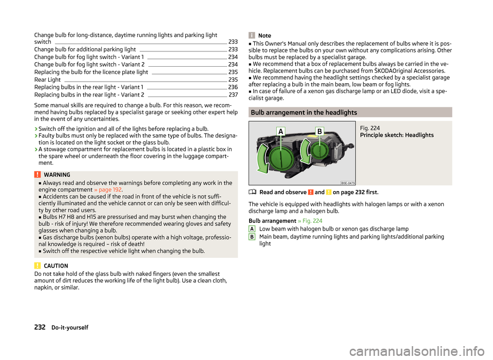
Fig. 224
Principle sketch: Headlights
Read and observe and on page 232 first.
The vehicle is equipped with headlights with halogen lamps or with a xenon
discharge lamp and a halogen bulb.
Bulb arrangement » Fig. 224
Low beam with halogen bulb or xenon gas discharge lamp
Main beam, daytime running lights and parking lights/additional parking
light
AB232Do-it-yourself
Page 236 of 280
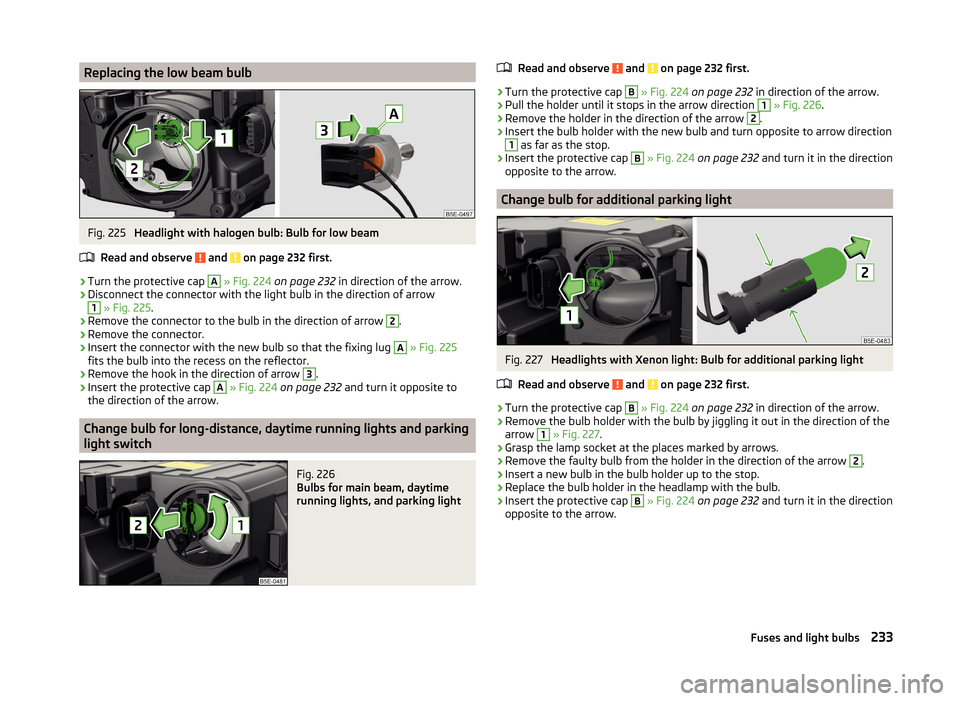
Replacing the low beam bulbFig. 225
Headlight with halogen bulb: Bulb for low beam
Read and observe
and on page 232 first.
›
Turn the protective cap
A
» Fig. 224 on page 232 in direction of the arrow.
›
Disconnect the connector with the light bulb in the direction of arrow
1
» Fig. 225 .
›
Remove the connector to the bulb in the direction of arrow
2
.
›
Remove the connector.
›
Insert the connector with the new bulb so that the fixing lug
A
» Fig. 225
fits the bulb into the recess on the reflector.
›
Remove the hook in the direction of arrow
3
.
›
Insert the protective cap
A
» Fig. 224 on page 232 and turn it opposite to
the direction of the arrow.
Change bulb for long-distance, daytime running lights and parking
light switch
Fig. 226
Bulbs for main beam, daytime
running lights, and parking light
Read and observe and on page 232 first.›
Turn the protective cap
B
» Fig. 224 on page 232 in direction of the arrow.
›
Pull the holder until it stops in the arrow direction
1
» Fig. 226 .
›
Remove the holder in the direction of the arrow
2
.
›
Insert the bulb holder with the new bulb and turn opposite to arrow direction
1
as far as the stop.
›
Insert the protective cap
B
» Fig. 224 on page 232 and turn it in the direction
opposite to the arrow.
Change bulb for additional parking light
Fig. 227
Headlights with Xenon light: Bulb for additional parking light
Read and observe
and on page 232 first.
›
Turn the protective cap
B
» Fig. 224 on page 232 in direction of the arrow.
›
Remove the bulb holder with the bulb by jiggling it out in the direction of the
arrow
1
» Fig. 227 .
›
Grasp the lamp socket at the places marked by arrows.
›
Remove the faulty bulb from the holder in the direction of the arrow
2
.
›
Insert a new bulb in the bulb holder up to the stop.
›
Replace the bulb holder in the headlamp with the bulb.
›
Insert the protective cap
B
» Fig. 224 on page 232 and turn it in the direction
opposite to the arrow.
233Fuses and light bulbs
Page 263 of 280
Index
A
abroad lead-free petrol
189
Abroad Headlights
78
ABS Function
138
Warning light37
ACC149
Control symbols44
Warning light36
Acceptance and recycling of used vehicles180
Accessories177
Adaptive cruise control149
automatic stop-start152
Information messages155
Operation151
Operation Overview152
Radar sensor150
Set/change the desired speed.153
Set time interval level153
special driving conditions154
Start control152
Stop/resume control153
Adaptive headlights (AFS)
74
Adjust Auxiliary heating (auxiliary heating and ventila-tion)
122
Adjusting Belt height
15
Exterior mirrors85
head restraints88
Interior mirror84
seats87
Steering wheel10
the seats electronically87
Adjusting the seats9
Adjusting the seats electronically87
Adjustment Headlight beam
71
Advance warning/emergency brake Warning symbol
45
AFS74
Air-conditioning system Air outlet vents
116
Airbag16
Deactivating21
Deactivating the front passenger airbag21
Deployment16
Front airbag17
Head airbag20
Knee airbag18
Modifications and damage to the airbag system 179
Side airbag
19
Air bag Warning light
38
Airbag system16
Air conditioning116
Air distribution control117
Climatronic119
manual air conditioning119
Air distribution control117
Air outlet vents116
Alarm Switching off
59
Triggering59
Alcantara cleaning
187
Anti-theft alarm system Activating/deactivating
59
Trailer176
Anti-theft wheel bolts217
Antilock Braking System138
Armrest Front
91
Rear91
artificial leather187
Ashtray97
ASR warning light
37
Assistance systems ACC
36
Driving mode160
ESC138
Front Assistant155
High beam assistant75
Lane Assist162
MCB140
TSA140
Assist system ABS
138
Assist systems138
ABS37
Adaptive cruise control149
ASR37
Cruise Control System148
DSR139
EDL139
ESC37
HBA140
HHC140
Park assist144
Parking aid140
ProActive passenger protection161
START-STOP158
TCS139
XDS139
Audio see radio/navigation system
4
Auto-check control47
Automatic driving lamp control73
Automatic gearbox133
Selector lever-emergency unlocking226
Selector lever lock134
Starting-off and driving135
Tiptronic134
Using the selector lever133
260Index
Page 264 of 280
Automatic gearbox modes133
Automatic load deactivation203
automatic transmission selector lever lock defect
134
Automatic transmission Kickdown
135
Launch control135
Selector lever lock134
Automatic Transmission Malfunction
35
Warning light35
warning messages35
Auxiliary heating (auxiliary heating and ventila- tion)
121
Adjust122
Radio remote control123
Switching on/off122
B
Ball head Check fitting
172
Ready position170
Ball rod assembling, step 1
171
assembling, step 2171
Ready position170
removing, step 1172
removing, step 2173
Battery In the remote control key
224
Belts12
Belt tensioners15
Bonnet Closing
194
Opening194
Boot Class N1 vehicles
110
See Boot lid61
Boot lid automatic locking61
Closing61
Opening61
Brake information messages
35
warning light35
Brake booster131
brake fluid specification
199
Brake fluid199
Checking199
information messages35
Brake linings warning light
39
Brake pedal (automatic transmission) Indicator light
40
brakes Driving in
136
Brakes Brake booster
131
Brake fluid199
Braking and stabilisation systems138
Handbrake131
Brakes and parking130
Braking Information on braking
130
Break recommendation See Fatigue detection
166
Bulbs Replacing
231
Buttons in the door Power windows
64
C
Camera Lens care
184
Camera lens care
184
Car computersee multifunction display47
Care and maintenance177
cargo cover roll-up cargo cover
108
Cargo element108
Caring for the vehicle exterior Towing hitch
185
Car park132
Car park ticket holder95
Carrier Roof rack
113
Cavity protection184
Central locking54
Problems58
Central locking button58
Central warning light Indicator light
36
Change bulb for additional parking light
233
bulb for fog lights - Version 1234
bulb for fog lights - Version 2234
bulb for high beam233
bulb for the parking light233
bulb in the rear light - Version 1236
bulb in the rear light - Version 2237
daytime running light bulb233
light bulb in tail light235
Changing Engine oil
195
Wheels214
Changing a wheel Follow-up tasks
215
Preparation214
Removing and refitting a wheel215
Charging a vehicle battery202
Check Fit ball head properly
172
261Index
Page 266 of 280
Cruise Control System148
Cup holders96
D
DAY LIGHT see Daylight running lights
72
Daylight running lights72
De-icing windows
183
De-icing the windscreen and rear window80
Deactivating an airbag21
Decorative films183
Delayed locking of the boot lid see boot lid
61
Departure angle244, 245
Diesel refer to Fuel
190
Diesel fuel Operation in winter
190
Diesel particulate filter43
information messages43
Digital Clock Time
33
Dipstick196
Disconnecting and reconnecting vehicle battery
202
Display31
Compass points52
Coolant temperature32
Gear changes46
Natural gas reserve32
Petrol / Diesel reserve33
Service interval53
Disposal Acceptance and recycling of used vehicles
180
Distance driven33
Distance warning Warning symbol
44
DoorChild safety lock58
Closing56
Emergency locking226
Emergency locking the driver's door225
Opening56
Door warning47
double hooks105
Driver Steering Recommendation (DSR)139
Driving Driving through water
137
Emissions239
Fuel consumption239
off of made-up roads137
Driving in Brake linings
136
engine136
Tyres136
Driving mode160
driving mode select Normal mode
160
Driving Mode Selection160
Driving off of made-up roads137
Driving through water137
DSR139
E
ECO-TIP
52
Eco-tips52
Economical driving Tips
136
EDL139
Electrical power windows66
Operational faults66
Electric boot lid Force limit
61
Manual operation61
Electric luggage compartment lid Acoustic signals63
Adjusting the top lid position63
Deleting the top lid position63
Malfunctions63
Operating62
Electronic Differential Lock (EDL)139
Electronic immobilizer126
Electronic Stability Control (ESC)138
emergency replace battery in the remote control
225
Emergency Changing a wheel
214
Hazard warning light system77
Jump-starting220
Locking the door without a locking cylinder226
Locking the driver's door225
Selector lever-unlocking226
Switching off the engine by pressing a button 129
Towing the using the tow hitch
223
Towing the vehicle221
Tyre repair218
Unlocking the driver's door225
Unlocking the tailgate226
Emergency equipment Fire extinguisher
211
First-aid kit 211
Jack212
Reflective vest211
Vehicle tool kit212
Warning triangle211
Emergency spare wheel Changing
213
Emissions239
Engine Information messages
41
Engine compartment192
Brake fluid199
Overview194
Vehicle battery200
263Index
Page 273 of 280
Tyres204
Explanation of the labelling207
new136
see wheels207
Tyre pressure204
Wear205
Wear indicator206
Tyre size207
see wheels207
U
Under-body Vehicle care
185
Under-body protection185
Unlocking Individual settings
57
KESSY56
Key55
Remote control55
Unlocking and locking54
Used vehicles Acceptance and recycling
180
Useful equipment 230-volt socket
101
Ashtray97
Car park ticket holder95
Cigarette lighter97
Clothes hook101
Cup holders96
Glasses compartment100
Multimedia holder99
Removable through-loading bag102
Seat backrest with long-cargo channel94
Storage compartment94
Using the information system46
Using the selector lever133
V
Variable loading floor
110
Dividing the luggage compartment112
Folding up111
Position change111
Vehicle battery Automatic load deactivation
203
Charge level indicator34
charging202
Checking the battery electrolyte level201
Cover201
Operation in winter201
Replacing202
Safety instructions200
Warning icon41
vehicle care chrome parts
183
Vehicle care Alcantara
187
Artificial leather187
Cavity protection184
Cleaning vehicle exterior181
Cleaning wheels185
Decorative films183
Door locking cylinder184
Headlight glasses184
Interior care185
Jack184
Maintenance182
Materials187
Natural leather186
Plastic parts182
Polishing vehicle paint work182
Rubber seals183
Safety belt187
Seat covers187
Under-body protections185
washing180
Vehicle condition see Auto-check control
47
Vehicle data sticker238
Vehicle data sticker and nameplate Vehicle data sticker and nameplate
238
Vehicle dimensions240, 242
Vehicle height240, 242
Vehicle Identification Number (VIN)238
Vehicle length240, 242
Vehicle tool kit212
Vehicle width240, 242
Vest Location of the reflective vest
211
VIN Vehicle Identification Number
238
Visibility80
Visors see front sun visors
81
see Sun screen81
W
Warning at excessive speeds
50
Warning icons40
Warning indicator of a low temperature Warning symbol
44
Warning lights34
Warning symbols see Warning lights
34
see Warning symbols40
Warning triangle211
Washing Automatic car wash system
181
by hand181
High-pressure cleaner181
Washing vehicles180
Waste container98
Water Driving through
137
Water in the fuel filter Information messages
44
Warning symbol44
270Index