fuel SKODA OCTAVIA 2014 3.G / (5E) Owner's Guide
[x] Cancel search | Manufacturer: SKODA, Model Year: 2014, Model line: OCTAVIA, Model: SKODA OCTAVIA 2014 3.G / (5E)Pages: 280, PDF Size: 35.53 MB
Page 86 of 280
Automatic windscreen wiping in rain can be activated or deactivated in the In-
fotainment » Operating instructions for Infotainment , chapter Vehicle settings
(CAR button) .
Automatic wiping/washing for the windscreen
The wash system operates immediately, the windscreen wipers wipe some- what later. The wash system and the windscreen wiper operate simultaneous-
ly at a speed of more than 120 km/h.
Letting go of the operating lever will cause the windscreen wash system to
stop and the wipers to continue for another 2-3 wiper strokes (depending on
the spraying duration).
At a speed of more than 2 km/h, the wiper wipes once again 5 seconds after
the last wiper stroke in order to wipe the last drops from the windscreen. This
function can be activated/deactivated by a specialist garage.
Automatic wiping/washing for the rear window
The wash system operates immediately, the windscreen wiper wipes some-
what later.
Letting go of the operating lever will cause the windscreen wash system to
stop and the wiper to continue for another 2-3 wiper strokes (depending on
the spraying duration). The operating lever remains in position 6
.
Automatic rear window wiping
If the lever is in position
2
or
3
» Fig. 63 , the rear window is wiped every
30 or 10 seconds if the vehicle's speed exceeds 5 km/h.
If automatic windscreen wiping in rain is activated (the operating lever is in the position
1
) the function is only active if the windscreen wipers operate in
continuous mode (no break between each wiping process).
Automatic rear window wiping can be activated or deactivated in the Infotain-
ment » Operating instructions for Infotainment , chapter Vehicle settings (CAR
button) .
Winter setting of the windscreen wiper
If the windscreen wipers are in rest position, they cannot be folded out from
the windscreen. For this reason we recommend adjusting the windscreen wip-
ers in winter so that they can be folded out from the windscreen easily.
› Switch on the windscreen wipers.
› Switch off the ignition.
The windscreen wipers remain in the position in which they were when
switching off the ignition.
The service position can also be used as a winter position » page 227.
Note
■
If the operating lever is in the position 2 or 3 and the speed of the vehicle
drops below 4 km / h, the wiping speed is switched to a lower wiping level.
The original setting is restored step by step when the speed of the vehicle ex-
ceeds 8 km/h.■
The rear window is wiped once automatically if the windscreen wipers are on
when reverse gear is selected.
Headlight cleaning system
Read and observe
and on page 81 first.
After the ignition is switched on, the headlights are always cleaned at the first
and after every tenth spray of the windscreen (setting
5
» Fig. 63 on
page 82 ), when the low beam or main beam is switched on.
You should manually remove stubborn dirt (such as insect residues) from the headlight lenses at regular intervals, for example after refuelling. The follow-
ing guidelines must be observed » page 184, Headlight glasses .
To ensure the proper operation of the cleaning system during the winter, any snow should be removed from the washer nozzle fixtures and ice should be
cleared with a de-icing spray.
CAUTION
Never remove the nozzles from the headlight cleaning system by hand – risk of
damage!
Note
The headlamp cleaning system works with an ambient temperature of about
-12 ° C to + 39 ° C.
Rear mirror
Introduction
This chapter contains information on the following subjects:
Interior mirror
84
Exterior mirrors
85
83Lights and visibility
Page 99 of 280
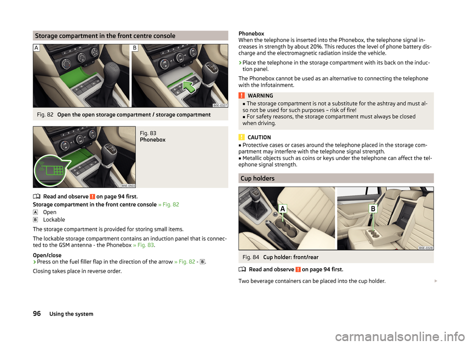
Storage compartment in the front centre consoleFig. 82
Open the open storage compartment / storage compartment
Fig. 83
Phonebox
Read and observe on page 94 first.
Storage compartment in the front centre console » Fig. 82
Open
Lockable
The storage compartment is provided for storing small items.
The lockable storage compartment contains an induction panel that is connec- ted to the GSM antenna - the Phonebox » Fig. 83.
Open/close
›
Press on the fuel filler flap in the direction of the arrow » Fig. 82 -
.
Closing takes place in reverse order.
Phonebox
When the telephone is inserted into the Phonebox, the telephone signal in-
creases in strength by about 20%. This reduces the level of phone battery dis-
charge and the electromagnetic radiation inside the vehicle.›
Place the telephone in the storage compartment with its back on the induc-
tion panel.
The Phonebox cannot be used as an alternative to connecting the telephone with the Infotainment.
WARNING■ The storage compartment is not a substitute for the ashtray and must al-
so not be used for such purposes – risk of fire!■
For safety reasons, the storage compartment must always be closed
when driving.
CAUTION
■ Protective cases or cases around the telephone placed in the storage com-
partment may interfere with the telephone signal strength.■
Metallic objects such as coins or keys under the telephone can affect the tel-
ephone signal strength.
Cup holders
Fig. 84
Cup holder: front/rear
Read and observe
on page 94 first.
Two beverage containers can be placed into the cup holder.
96Using the system
Page 117 of 280
WARNING■The items which you transport on the roof rack must be reliably attached
– risk of accident!■
Always secure the load with appropriate and undamaged lashing straps
or tensioning straps.
■
Distribute the load evenly over the roof rack system.
■
When transporting heavy objects or objects which take up a large area on
the roof rack system, the handling of the car may change as a result of the
displacement of the centre of gravity. The style of driving and speed must
therefore be adapted to the current circumstances.
■
Avoid abrupt and sudden driving/braking manoeuvres.
■
The permissible roof load, permissible axle loads and gross permissible
weight of the vehicle must not be exceeded under any circumstances – risk
of accident!
CAUTION
■ Only roof racks from the ŠKODA Original Accessories range should be used.■When dealing with roof rack systems, the installation instructions supplied
with the roof luggage rack system must be observed.■
On models fitted with a sliding/tilting roof, ensure that the sliding/tilting roof
does not strike any items of luggage transported on the roof.
■
Ensure that the luggage compartment lid does not hit the roof load when
opened.
■
The height of the vehicle changes after mounting a roof luggage rack system
and the load that is secured to it. Compare the vehicle height with available
clearances, such as underpasses and garage doors.
■
Always remove the roof luggage rack system before entering an automated
car wash.
■
Ensure the roof aerial is not impaired by the secured load.
For the sake of the environment
The increased aerodynamic drag results in a higher fuel consumption.fixing points for base supportFig. 120
Attachment points
Read and observe
and on page 114 first.
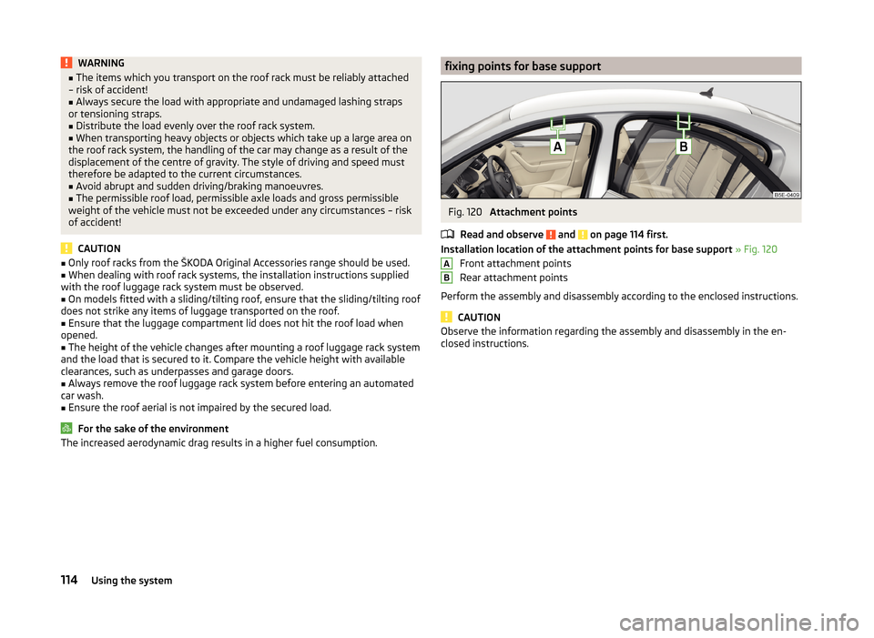
Installation location of the attachment points for base support » Fig. 120
Front attachment points
Rear attachment points
Perform the assembly and disassembly according to the enclosed instructions.
CAUTION
Observe the information regarding the assembly and disassembly in the en-
closed instructions.AB114Using the system
Page 124 of 280
■As soon as the windscreen mists up, press the symbol button . Press the
button once the windscreen has demisted.■
During operation of the Climatronic, an increase in engine idle speed can oc-
cur under certain circumstances in order to ensure adequate heating comfort.
Efficient handling of the cooling system
Read and observe
and on page 116 first.
The air conditioning system compressor uses power from the engine when in
cooling mode, which will affect the fuel consumption.
It recommended to open the windows or the doors of a vehicle for which the
interior has been strongly heated through the effect of direct sunlight in order
to allow the heated air to escape.
The cooling system should not be on if the windows are open.
For the sake of the environment
Pollutant emissions are also lower when fuel is being saved » page 136.
malfunctions
Read and observe
and on page 116 first.
If the cooling system does not operate at outside temperatures higher than
+5 °C, there is a problem in the system. The reasons for this may be.
› One of the fuses has blown. Check the fuse and replace if necessa-
ry » page 229 .
› The cooling system has switched off automatically for a short time because
the coolant temperature of the engine is too hot » page 32.
If you are not able to resolve the operational problem yourself, or if the cooler
output has reduced, switch off the cooling system and seek assistance from a
specialist garage.
Auxiliary heating (auxiliary heating and ventilation)
Introduction
This chapter contains information on the following subjects:
Switching on/off
122
Radio remote control
123Conditions for the functioning of auxiliary heating (auxiliary heating and venti-
lation), hereinafter referred to only as auxiliary heating.
The charge state of the vehicle battery is sufficient.
The fuel supply is adequate (the warning icon
is not lit in the display of
the instrument cluster).
Auxiliary ventilation
The auxiliary ventilation enables fresh air to flow into the vehicle interior by
switching off the engine, whereby the interior temperature is effectively de-
creased (e.g. with the vehicle parked in the sun).
Auxiliary heating (parking heating)
The auxiliary heating can be used when both when stationary, when the en-
gine is switched off, to preheat the vehicle and also while driving (e.g. during
the heating phase of the engine).
The auxiliary heater functions in connection with the air-conditioning system
or Climatronic.
The auxiliary heating also warms up the engine.
The auxiliary heating warms up the coolant by combusting fuel from the vehi-
cle tank. This heats the air flowing into the passenger compartment (if the
blower is turned on).
The heater is switched on or off automatically depending on the ambient con-
ditions to give the best possible conditions for the engine running and the in-
terior heating.
The automatic switching on and off of the heater can be turned off by a spe-
cialist garage.WARNING■ The auxiliary heating must never be operated in closed rooms (e.g. garag-
es) – risk of poisoning!■
The auxiliary heating must not be allowed to run during refuelling – risk
of fire.
■
The exhaust pipe of the auxiliary heating is located on the underside of
the vehicle. If you want to use the heater, do not park the car in places
where the exhaust fumes can come into contact with flammable materials
such as dry grass, undergrowth, leaves, spilled fuel etc. - risk of fire.
121Heating and air conditioning
Page 125 of 280
CAUTION■The running auxiliary heater consumes fuel from the vehicle tank and auto-
matically controls the filling level. If only a low quantity of fuel is present in the
fuel tank, the auxiliary heating switches off.■
The exhaust pipe of the auxiliary heating, which is located on the underside
of the vehicle, must not be clogged and the exhaust flow must not be blocked.
■
If the auxiliary heating is running, the vehicle battery discharges. If the auxili-
ary heating and ventilation has been operated several times over a longer peri-
od, the vehicle must be driven a few kilometres in order to recharge the vehi-
cle battery.
■
The air inlet in front of the windscreen must be free (e.g. of ice, snow or
leaves) to ensure that the auxiliary heating operates properly.
Note
■ The auxiliary heating switches on the blower B » Fig. 125 on page 119 orC » Fig. 126 on page 119 only if it has achieved a coolant temperature of ap-
prox. 50 °C.■
At low outside temperatures, this can result in a formation of water vapour in
the area of the engine compartment. This is quite normal and is not an operat-
ing problem.
■
So that warm air can flow into the vehicle interior after switching on the aux-
iliary heating, you must maintain the comfort temperature normally selected
by you, leave the fan switched on and leave the air outlet vents in an open po-
sition. It is recommended to put the air flow in the position
or
.
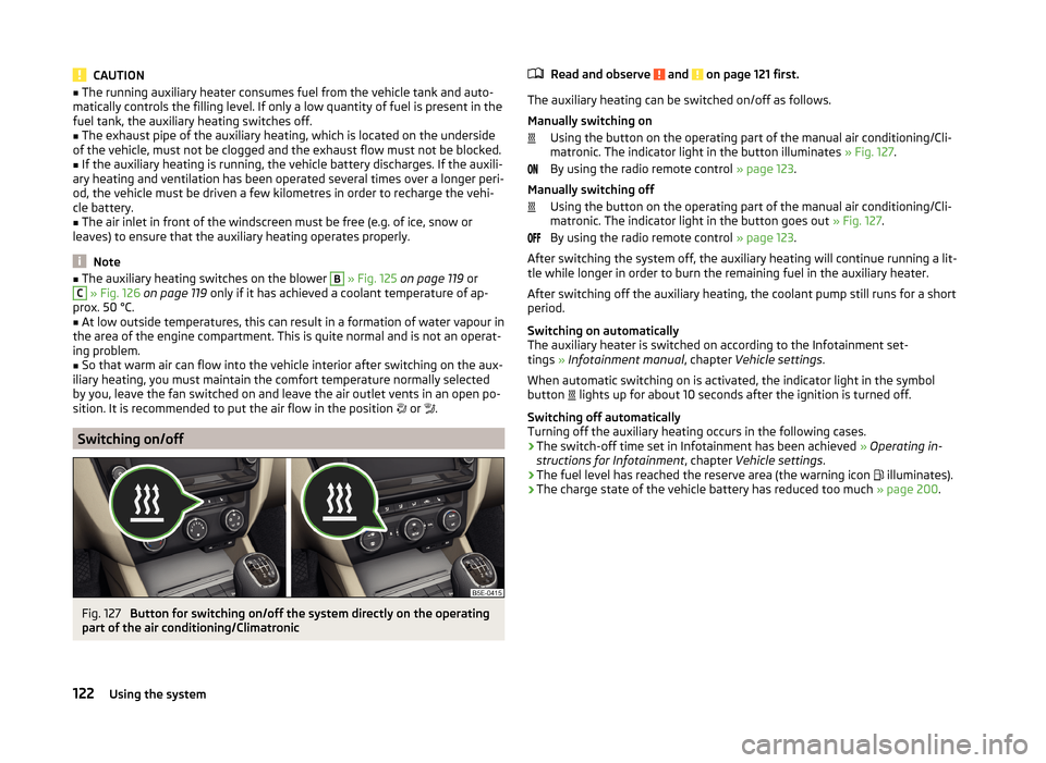
Switching on/off
Fig. 127
Button for switching on/off the system directly on the operating
part of the air conditioning/Climatronic
Read and observe and on page 121 first.
The auxiliary heating can be switched on/off as follows.
Manually switching on Using the button on the operating part of the manual air conditioning/Cli-
matronic. The indicator light in the button illuminates » Fig. 127.
By using the radio remote control » page 123.
Manually switching off Using the button on the operating part of the manual air conditioning/Cli-
matronic. The indicator light in the button goes out » Fig. 127.
By using the radio remote control » page 123.
After switching the system off, the auxiliary heating will continue running a lit- tle while longer in order to burn the remaining fuel in the auxiliary heater.
After switching off the auxiliary heating, the coolant pump still runs for a short
period.
Switching on automatically
The auxiliary heater is switched on according to the Infotainment set-
tings » Infotainment manual , chapter Vehicle settings .
When automatic switching on is activated, the indicator light in the symbol
button lights up for about 10 seconds after the ignition is turned off.
Switching off automatically
Turning off the auxiliary heating occurs in the following cases.
› The switch-off time set in Infotainment has been achieved
» Operating in-
structions for Infotainment , chapter Vehicle settings .
› The fuel level has reached the reserve area (the warning icon
illuminates).
› The charge state of the vehicle battery has reduced too much
» page 200.
122Using the system
Page 135 of 280
The handbrake warning is activated if the vehicle is driven at a speed of more
than around 5 km/h for more than 3 seconds.WARNINGPlease note that the handbrake must be fully released. A handbrake which
is only partially released can result in the rear brakes overheating. This can
have a negative effect on the operation of the brake system – risk of acci-
dent!
Parking
Read and observe
and on page 130 first.
When stopping and parking, look for a place with a suitable surface » .
Only carry out the activities while parking in the specified order.
›
Bring the vehicle to a stop and depress the brake pedal.
›
Firmly apply the handbrake.
›
On vehicles with automatic transmission place the selector lever in the P po-
sition.
›
Switch off the engine.
›
For vehicles with manual transmission , select 1st gear or reverse gear
›
Release the brake pedal.
WARNINGThe parts of the exhaust system can become very hot. Therefore, never
stop the vehicle at places where the underside of your vehicle can come in-
to contact with flammable materials such as dry grass, undergrowth,
leaves, spilled fuel or such like. - Risk of fire and serious injury can occur!
Manual shifting of gears and pedals
Introduction
This chapter contains information on the following subjects:
Manual gear changing
132
Pedals
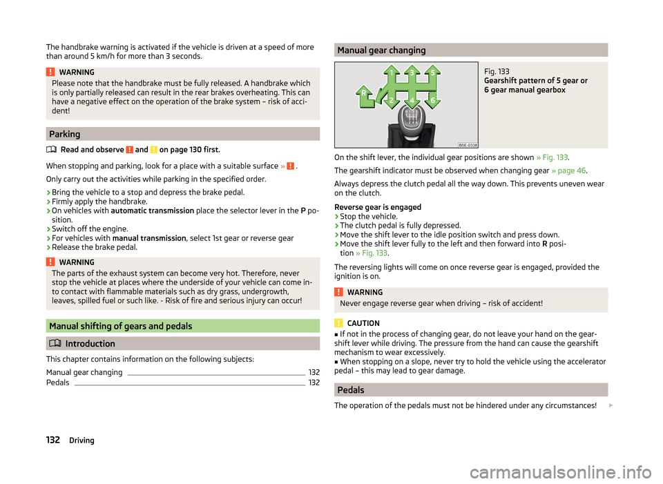
132Manual gear changingFig. 133
Gearshift pattern of 5 gear or
6 gear manual gearbox
On the shift lever, the individual gear positions are shown » Fig. 133.
The gearshift indicator must be observed when changing gear » page 46.
Always depress the clutch pedal all the way down. This prevents uneven wear
on the clutch.
Reverse gear is engaged
›
Stop the vehicle.
›
The clutch pedal is fully depressed.
›
Move the shift lever to the idle position switch and press down.
›
Move the shift lever fully to the left and then forward into R posi-
tion » Fig. 133 .
The reversing lights will come on once reverse gear is engaged, provided the ignition is on.
WARNINGNever engage reverse gear when driving – risk of accident!
CAUTION
■ If not in the process of changing gear, do not leave your hand on the gear-
shift lever while driving. The pressure from the hand can cause the gearshift
mechanism to wear excessively.■
When stopping on a slope, never try to hold the vehicle using the accelerator
pedal – this may lead to gear damage.
Pedals
The operation of the pedals must not be hindered under any circumstances!
132Driving
Page 139 of 280
Reactivate the TCS and START-STOP when the desired speed has been
reached.WARNINGRapid acceleration, particularly on slippery roads, can lead to loss of control
of the vehicle – risk of accident!
Retraction and economical driving
Introduction
This chapter contains information on the following subjects:
Driving in
136
Tips for economical driving
136
The fuel consumption, degree of pollution and vehicle wear depend on driving
style, road condition, weather conditions and the like.
Driving in
Driving in the engine
The engine has to be run in during the first 1500 kilometres. During this period,
the driving style decides on the quality of the driving-in process.
During the first 1 000 km we recommend not driving faster than 3/4 of the
maximum permissible engine speed, not to drive at full throttle and to dis-
pense with the trailer.
In the area of 1,000 to 1,500 kilometres the engine load can be increased up
to the maximum permitted engine speed.
New tyres
New tyres have to be “run in” since they do not offer optimal grip at first.
Drive especially carefully for the first 500 km or so.
New brake pads
New brake pads have to first “grind in” because these do not initially have the
best possible braking effect.
Drive especially carefully for the first 200 km or so.
Tips for economical driving
To achieve the lowest possible fuel consumption, the following instructions
must be observed.
Looking ahead when driving
Avoid unnecessary acceleration and braking.
Switch in an energy saving and timely manner Observe the recommended gear » page 46.
Avoid full throttle and high speeds
Fuel consumption will be halved if only three-quarters of the possible top
speed of your vehicle is used.
Reducing idling
When the engine is switched off, such as when waiting in a traffic jam, the fuel
economy is already greater after 30 - 40 s than the fuel quantity which is re-
quired for engine re-start.
Avoid short distances
When driving a short distance of less than about 4 km, the engine cannot
reach its operating temperature. As long as the engine has not reached oper-
ating temperature, the fuel consumption is significantly higher than with the
engine hot.
Pay attention to the correct tyre inflation pressure being maintained
Further information » page 204.
Avoid unnecessary ballast
Per 100 kg of weight, consumption increases by about 1 l/100 km. At a speed of
100-120 km/h, a vehicle fitted with a roof rack cross member without a load
will use about 10 % more fuel than normal due to the increased aerodynamic
drag.
Saving electricity
Electrical consumers (e.g. seat heating, air conditioning and the like) only turn
on for as long as necessary.
In Infotainment, the display is shown of up to three consumers which are cur-
rently showing the highest degree of fuel consumption » Infotainment operat-
ing instructions , chapter Vehicle settings (CAR button) .136Driving
Page 140 of 280
Driving through water and driving off of made-up roads
Introduction
This chapter contains information on the following subjects:
Driving through water
137
Driving off paved roads
137WARNINGImmediately after driving through water, mud, slush and the like, braking
effectiveness will be temporarily impaired » page 130, Information on brak-
ing . For this reason, sudden and violent braking manoeuvres are to be
avoided - there is a risk of accident!
Driving through water
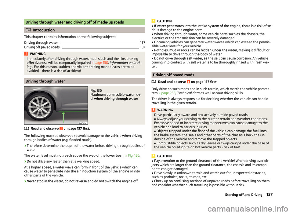
Fig. 136
Maximum permissible water lev-
el when driving through water
Read and observe on page 137 first.
The following must be observed to avoid damage to the vehicle when driving through bodies of water (e.g. flooded roads).
›
Therefore determine the depth of the water before driving through bodies of
water.
The water level must not reach above the web of the lower beam » Fig. 136.
›
Do not drive any faster than at a walking speed.
At a higher speed, a water wave can form in front of the vehicle which can
cause water to penetrate into the air induction system of the engine or into
other parts of the vehicle.
›
Never stop in the water, do not reverse and do not switch the engine off.
CAUTION■ If water penetrates into the intake system of the engine, there is a risk of se-
rious damage to the engine parts!■
When driving through water, some vehicle parts such as the chassis, the
electrics or the transmission can be severely damaged.
■
Oncoming vehicles can generate water waves which can exceed the permis-
sible water level for your vehicle.
■
Potholes, mud or rocks can be hidden under the water, making it difficult or
impossible to drive through the body of water.
■
Do not drive through salt water, as the salt can cause corrosion. An vehicle
coming into contact with salt water is to be thoroughly rinsed with fresh wa-
ter.
Driving off paved roads
Read and observe
on page 137 first.
Only drive on such roads and in such terrain, which match the vehicle parame-ters » page 238 , Technical data as well as your driving skills.
The driver is always responsible for deciding whether the vehicle can handle
travelling in the given terrain.
WARNINGDrive particularly aware and pro-actively outside paved roads.■Always adjust your driving to the current terrain and weather conditions.
Excessive speed or incorrect driving manoeuvres can cause damage to the
vehicle and lead to serious injuries.■
Objects trapped under the floor of the vehicle can damage the fuel lines,
the brake system, the seals and other parts of the chassis. Check the un-
derside of the vehicle and remove the trapped objects.
■
Combustible objects such as dry leaves or twigs caught under the base of
the vehicle could ignite on hot vehicle parts - risk of fire!
CAUTION
■ Pay attention to the ground clearance of the vehicle! When driving over ob-
jects which are larger than the ground clearance, the chassis and its compo-
nents can get damaged.■
Drive slowly in unknown terrain and watch out for unexpected obstacles,
such as potholes, rocks, stumps, etc.
■
Check up on confusing sections of unpaved roads before travelling on them
and consider whether such travelling is possible without risk.
137Starting-off and Driving
Page 141 of 280
Assist systems
Braking and stabilisation systems
Introduction
This chapter contains information on the following subjects:
Electronic Stability Control (ESC)
138
Antilock Braking System (ABS)
138
Traction Control System (TCS)
139
Electronic Differential Lock (EDL and XDS)
139
Driver Steering Recommendation (DSR)
139
Hydraulic Brake Assist (HBA)
140
Hill Hold Control (HHC)
140
Multi-collision brake (MCB)
140
Trailer stabilisation (TSA)
140
This chapter deals with the functions of the braking and stabilisation systems,
with the error indicator referred to in chapter » page 34, Warning lights .
The braking and stabilisation systems are automatically activated each time
the ignition is switched on.
WARNING■ A lack of fuel can cause irregular engine running or cause the engine to
shut down. The brake assist systems would then fail to function – risk of
accident!■
The increased safety provided by the brake assist systems must not
tempt you to take safety risks – risk of accident!
■
Always adjust your speed and driving style to the current visibility, weath-
er, road and traffic conditions.
Electronic Stability Control (ESC)
Read and observe
on page 138 first.
The ESC improves vehicle stability in dynamic driving situations, such as when
the vehicle starts to skid.
The ESC monitors whether the desired direction of the current vehicle motion
is occurring. In case of any deviation (e.g. oversteer), the ESC automatically
brakes individual wheels to maintain the desired direction.
During an intervention of the system, the warning light flashes in the instru-
ment cluster.
Enable/disable ESC Sport
ESC Sport allows for sportier driving style. The activation of the ESC sport
leads to the ASR being deactivated and no ESC interventions will occur in the
event of slight over- or under-steering occurring.
The activation or deactivation of the ESC sports can be done in one of two
ways.
› By pressing the Symbol key
for the activation and briefly pressing the but-
ton for the deactivation » Fig. 137 on page 139 .
› In Infotainment
» Operating instructions for Infotainment , chapter Vehicle
settings (CAR button) .
Upon activation, in the instrument cluster the indicator light comes on and
the display shows the following message.
ESC sport: Limited driving stability.
ESC SPORT
Upon deactivation, in the instrument cluster the control indicator turns off
and the display shows the following message.
Stabilisation control (ESC) activated.
ESC ON
Antilock Braking System (ABS)
Read and observe
on page 138 first.
ABS prevents the wheels locking when braking. Thus helping the driver to
maintain control of the vehicle.
The intervention of the ABS is noticeable from the pulsating movements of
the brake pedal which is accompanied by noises.
When the ABS system is active, do not brake periodically or reduce the pres- sure on the brake pedal.
138Driving
Page 161 of 280
START-STOP
Introduction
This chapter contains information on the following subjects:
Operating conditions of the system
158
Operation in vehicles with manual gearbox
158
Operation in vehicles with automatic gearbox
159
System related automatic start-up
159
Manually deactivating/activating the system
159
Information messages
160
The START-STOP system (hereinafter referred to as the system) saves fuel and
reduces polluting emissions and CO 2 emissions by turning the engine off, e.g.
when stopping at traffic lights, and starting the engine again when moving off.
WARNING■ Never let the vehicle roll with the engine switched off.■The brake servo unit and power steering only operate if the engine is run-
ning.
Operating conditions of the system
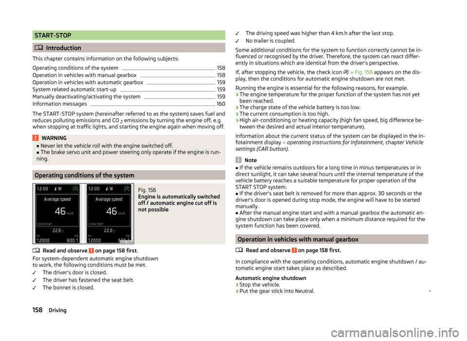
Fig. 156
Engine is automatically switched
off / automatic engine cut off is
not possible
Read and observe on page 158 first.
For system-dependent automatic engine shutdown
to work, the following conditions must be met.
The driver's door is closed.
The driver has fastened the seat belt.
The bonnet is closed.
The driving speed was higher than 4 km.h after the last stop.
No trailer is coupled.
Some additional conditions for the system to function correctly cannot be in-
fluenced or recognised by the driver. Therefore, the system can react differ-
ently in situations which are identical from the driver's perspective.
If, after stopping the vehicle, the check icon
» Fig. 156 appears on the dis-
play, then the conditions for automatic engine shutdown are not met.
Running the engine is essential for the following reasons, for example.
› The engine temperature for the proper function of the system has not yet
been reached.
› The charge state of the vehicle battery is too low.
› The current consumption is too high.
› High air-conditioning or heating capacity (high fan speed, big difference be-
tween the desired and actual interior temperature).
Information about the current status of the system can be displayed in the In-
fotainment display » operating instructions for Infotainment , chapter Vehicle
settings (CAR button) .
Note
■
If the vehicle remains outdoors for a long time in minus temperatures or in
direct sunlight, it can take several hours until the internal temperature of the
vehicle battery reaches a suitable temperature for proper operation of the
START STOP system.■
If the driver's seat belt is removed for more than approx. 30 seconds or the
driver's door is opened during stop mode, the engine will have to be started
manually.
■
After the manual engine start and with a manual gearbox the automatic en-
gine shutdown can take place only when a minimum distance required for the
system function has been covered.
Operation in vehicles with manual gearbox
Read and observe
on page 158 first.
In compliance with the operating conditions, automatic engine shutdown / au-
tomatic engine start takes place as described.
Automatic engine shutdown
›
Stop the vehicle.
›
Put the gear stick into Neutral.
158Driving