auxiliary battery SKODA OCTAVIA 2014 3.G / (5E) Owner's Manual
[x] Cancel search | Manufacturer: SKODA, Model Year: 2014, Model line: OCTAVIA, Model: SKODA OCTAVIA 2014 3.G / (5E)Pages: 280, PDF Size: 35.53 MB
Page 124 of 280
■As soon as the windscreen mists up, press the symbol button . Press the
button once the windscreen has demisted.■
During operation of the Climatronic, an increase in engine idle speed can oc-
cur under certain circumstances in order to ensure adequate heating comfort.
Efficient handling of the cooling system
Read and observe
and on page 116 first.
The air conditioning system compressor uses power from the engine when in
cooling mode, which will affect the fuel consumption.
It recommended to open the windows or the doors of a vehicle for which the
interior has been strongly heated through the effect of direct sunlight in order
to allow the heated air to escape.
The cooling system should not be on if the windows are open.
For the sake of the environment
Pollutant emissions are also lower when fuel is being saved » page 136.
malfunctions
Read and observe
and on page 116 first.
If the cooling system does not operate at outside temperatures higher than
+5 °C, there is a problem in the system. The reasons for this may be.
› One of the fuses has blown. Check the fuse and replace if necessa-
ry » page 229 .
› The cooling system has switched off automatically for a short time because
the coolant temperature of the engine is too hot » page 32.
If you are not able to resolve the operational problem yourself, or if the cooler
output has reduced, switch off the cooling system and seek assistance from a
specialist garage.
Auxiliary heating (auxiliary heating and ventilation)
Introduction
This chapter contains information on the following subjects:
Switching on/off
122
Radio remote control
123Conditions for the functioning of auxiliary heating (auxiliary heating and venti-
lation), hereinafter referred to only as auxiliary heating.
The charge state of the vehicle battery is sufficient.
The fuel supply is adequate (the warning icon
is not lit in the display of
the instrument cluster).
Auxiliary ventilation
The auxiliary ventilation enables fresh air to flow into the vehicle interior by
switching off the engine, whereby the interior temperature is effectively de-
creased (e.g. with the vehicle parked in the sun).
Auxiliary heating (parking heating)
The auxiliary heating can be used when both when stationary, when the en-
gine is switched off, to preheat the vehicle and also while driving (e.g. during
the heating phase of the engine).
The auxiliary heater functions in connection with the air-conditioning system
or Climatronic.
The auxiliary heating also warms up the engine.
The auxiliary heating warms up the coolant by combusting fuel from the vehi-
cle tank. This heats the air flowing into the passenger compartment (if the
blower is turned on).
The heater is switched on or off automatically depending on the ambient con-
ditions to give the best possible conditions for the engine running and the in-
terior heating.
The automatic switching on and off of the heater can be turned off by a spe-
cialist garage.WARNING■ The auxiliary heating must never be operated in closed rooms (e.g. garag-
es) – risk of poisoning!■
The auxiliary heating must not be allowed to run during refuelling – risk
of fire.
■
The exhaust pipe of the auxiliary heating is located on the underside of
the vehicle. If you want to use the heater, do not park the car in places
where the exhaust fumes can come into contact with flammable materials
such as dry grass, undergrowth, leaves, spilled fuel etc. - risk of fire.
121Heating and air conditioning
Page 125 of 280
CAUTION■The running auxiliary heater consumes fuel from the vehicle tank and auto-
matically controls the filling level. If only a low quantity of fuel is present in the
fuel tank, the auxiliary heating switches off.■
The exhaust pipe of the auxiliary heating, which is located on the underside
of the vehicle, must not be clogged and the exhaust flow must not be blocked.
■
If the auxiliary heating is running, the vehicle battery discharges. If the auxili-
ary heating and ventilation has been operated several times over a longer peri-
od, the vehicle must be driven a few kilometres in order to recharge the vehi-
cle battery.
■
The air inlet in front of the windscreen must be free (e.g. of ice, snow or
leaves) to ensure that the auxiliary heating operates properly.
Note
■ The auxiliary heating switches on the blower B » Fig. 125 on page 119 orC » Fig. 126 on page 119 only if it has achieved a coolant temperature of ap-
prox. 50 °C.■
At low outside temperatures, this can result in a formation of water vapour in
the area of the engine compartment. This is quite normal and is not an operat-
ing problem.
■
So that warm air can flow into the vehicle interior after switching on the aux-
iliary heating, you must maintain the comfort temperature normally selected
by you, leave the fan switched on and leave the air outlet vents in an open po-
sition. It is recommended to put the air flow in the position
or
.
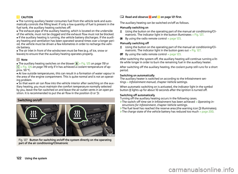
Switching on/off
Fig. 127
Button for switching on/off the system directly on the operating
part of the air conditioning/Climatronic
Read and observe and on page 121 first.
The auxiliary heating can be switched on/off as follows.
Manually switching on Using the button on the operating part of the manual air conditioning/Cli-
matronic. The indicator light in the button illuminates » Fig. 127.
By using the radio remote control » page 123.
Manually switching off Using the button on the operating part of the manual air conditioning/Cli-
matronic. The indicator light in the button goes out » Fig. 127.
By using the radio remote control » page 123.
After switching the system off, the auxiliary heating will continue running a lit- tle while longer in order to burn the remaining fuel in the auxiliary heater.
After switching off the auxiliary heating, the coolant pump still runs for a short
period.
Switching on automatically
The auxiliary heater is switched on according to the Infotainment set-
tings » Infotainment manual , chapter Vehicle settings .
When automatic switching on is activated, the indicator light in the symbol
button lights up for about 10 seconds after the ignition is turned off.
Switching off automatically
Turning off the auxiliary heating occurs in the following cases.
› The switch-off time set in Infotainment has been achieved
» Operating in-
structions for Infotainment , chapter Vehicle settings .
› The fuel level has reached the reserve area (the warning icon
illuminates).
› The charge state of the vehicle battery has reduced too much
» page 200.
122Using the system
Page 126 of 280
Radio remote controlFig. 128
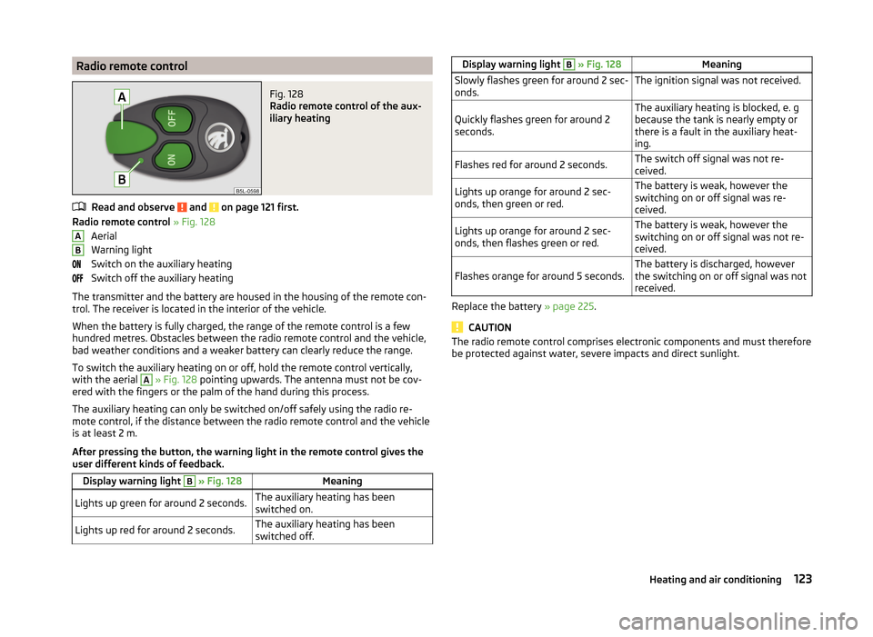
Radio remote control of the aux-
iliary heating
Read and observe and on page 121 first.
Radio remote control » Fig. 128
Aerial
Warning light
Switch on the auxiliary heating
Switch off the auxiliary heating
The transmitter and the battery are housed in the housing of the remote con-
trol. The receiver is located in the interior of the vehicle.
When the battery is fully charged, the range of the remote control is a few
hundred metres. Obstacles between the radio remote control and the vehicle,
bad weather conditions and a weaker battery can clearly reduce the range.
To switch the auxiliary heating on or off, hold the remote control vertically,
with the aerial
A
» Fig. 128 pointing upwards. The antenna must not be cov-
ered with the fingers or the palm of the hand during this process.
The auxiliary heating can only be switched on/off safely using the radio re-
mote control, if the distance between the radio remote control and the vehicle
is at least 2 m.
After pressing the button, the warning light in the remote control gives the
user different kinds of feedback.
Display warning light B » Fig. 128MeaningLights up green for around 2 seconds.The auxiliary heating has been
switched on.Lights up red for around 2 seconds.The auxiliary heating has been
switched off.ABDisplay warning light B » Fig. 128MeaningSlowly flashes green for around 2 sec-
onds.The ignition signal was not received.Quickly flashes green for around 2
seconds.The auxiliary heating is blocked, e. g
because the tank is nearly empty or
there is a fault in the auxiliary heat-
ing.Flashes red for around 2 seconds.The switch off signal was not re-
ceived.Lights up orange for around 2 sec-
onds, then green or red.The battery is weak, however the
switching on or off signal was re-
ceived.Lights up orange for around 2 sec-
onds, then flashes green or red.The battery is weak, however the
switching on or off signal was not re-
ceived.Flashes orange for around 5 seconds.The battery is discharged, however
the switching on or off signal was not
received.
Replace the battery » page 225.
CAUTION
The radio remote control comprises electronic components and must therefore
be protected against water, severe impacts and direct sunlight.123Heating and air conditioning
Page 205 of 280
Note■The battery acid level is also checked regularly by a specialist garage as part
of the inspection service.■
For technical reasons, on vehicles with the description “AGM”, the electrolyte
level cannot be checked.
Charging
Read and observe
and on page 200 first.
A properly charged vehicle battery is essential for reliably starting the engine.
A charging operation can be performed if the following conditions are satis-
fied.
The engine is turned off.
The ignition is switched off.
All consumers are turned off.
The bonnet is open.
“Fast charging” with high currents
›
Disconnect both battery cables (first of all “negative”, then “positive”).
›
Attach the terminal clamps of the charger to the battery terminals (red =
“positive”, black = “negative”).
›
Plug the mains cable of the charger into the power socket and switch on the
device.
›
After charging has been successful: Switch off the charger and remove the
mains cable from the power socket.
›
Only then disconnect the charger's terminal clamps.
›
Reconnect the cables to the battery (first of all “positive”, then “negative”).
Charging with low voltages
It is not necessary to disconnect the cables from the battery if you recharge
the vehicle battery, for example from a mini-charger.
Refer to the instructions of the charger manufacturer .
A charging current of 0.1 multiple of the total vehicle battery capacity (or low-
er) must be used until full charging is achieved.
The vent plugs of the vehicle battery should not be opened for charging.
WARNING■ When you charge a battery, hydrogen is released, and a highly explosive
gas mixture is also produced. An explosion can be caused through sparkling
over during unclamping or loosening of the cable plug while the ignition is
on.■
Creating a bridge between the poles on the battery (e.g. with metal ob-
jects - cables) creates a short circuit - risk of damage to the battery, explo-
sion and burning of the battery, jets of acid spurting out.
■
Avoid creating sparks when working with cables and electrical devices.
Strong sparking represents a risk of injury.
■
Before carrying out any work on the electrical system, switch off the en-
gine, the ignition and all electrical components and disconnect the negative
terminal
.
■
“Quick-charging” the vehicle battery is dangerous and requires a special
charger and specialist knowledge.
■
We therefore recommend that vehicle batteries be “rapidly charged” by a
specialist garage.
CAUTION
On vehicles with the START/STOP system or additional heating (auxiliary heat-
ing), do not connect the pole terminal of the charger directly to the negative
terminal of the vehicle battery, but rather only to the engine earth » page 220,
Jump-starting using the battery from another vehicle .
Replacing
Read and observe
and on page 200 first.
The new vehicle battery must have the same capacity, voltage, current and
size as the original battery. Suitable vehicle battery types can be purchased
from a specialist garage.
We recommend having the battery replaced by a specialist garage, where the
new vehicle battery will be installed properly and the original battery will be
disposed of in accordance with national regulations.
Disconnecting and reconnecting
Read and observe
and on page 200 first.
Disconnecting
›
Switch off the ignition.
202General Maintenance
Page 227 of 280
Towing the vehicle using the towing device is a viable alternative solution to
using the towing eye.
If the towing device is removed completely, it must be replaced with the
standard reinforcement of the rear bumper which is part of the mount for the
towing eye.
If this procedure is not observed, the vehicle may not meet the national legal
provisions.
CAUTION
The detachable ball rod and/or the vehicle can be damaged if an unsuitable
tow bar is used.
Note
The detachable ball rod must always be in the vehicle so that it can be used for
towing, if necessary.
Remote control
Introduction
This chapter contains information on the following subjects:
Replacing the battery in the remote control key
224
Synchronising the remote control
224
replace battery in the remote control the auxiliary heating (auxiliary
heating)
225
CAUTION
■ The replacement battery must have the same specification as the original
battery.■
We recommend having faulty rechargeable batteries replaced by a ŠKODA
service partner.
■
Pay attention to the correct polarity when changing the battery.
For the sake of the environment
Dispose of the used battery in accordance with national legal provisions.Replacing the battery in the remote control keyFig. 211
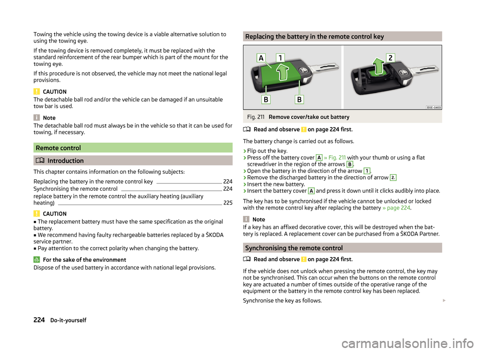
Remove cover/take out battery
Read and observe
on page 224 first.
The battery change is carried out as follows.
›
Flip out the key.
›
Press off the battery cover
A
» Fig. 211 with your thumb or using a flat
screwdriver in the region of the arrows
B
.
›
Open the battery in the direction of the arrow
1
.
›
Remove the discharged battery in the direction of arrow
2.›
Insert the new battery.
›
Insert the battery cover
A
and press it down until it clicks audibly into place.
The key has to be synchronised if the vehicle cannot be unlocked or locked
with the remote control key after replacing the battery » page 224.
Note
If a key has an affixed decorative cover, this will be destroyed when the bat-
tery is replaced. A replacement cover can be purchased from a ŠKODA Partner.
Synchronising the remote control
Read and observe
on page 224 first.
If the vehicle does not unlock when pressing the remote control, the key may
not be synchronised. This can occur when the buttons on the remote control
key are actuated a number of times outside of the operative range of the
equipment or the battery in the remote control key has been replaced.
Synchronise the key as follows.
224Do-it-yourself
Page 228 of 280
›Press any button on the remote control key.›Unlock the door with the key via the lock cylinder within 1 minute of pressing
the button.
replace battery in the remote control the auxiliary heating
(auxiliary heating)
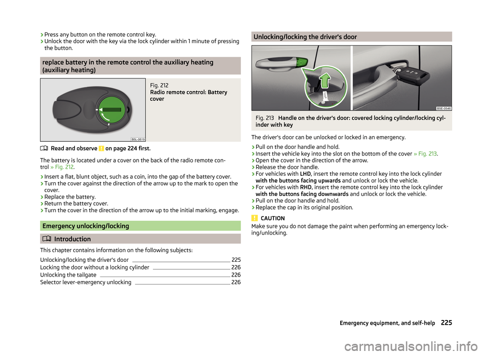
Fig. 212
Radio remote control: Battery
cover
Read and observe on page 224 first.
The battery is located under a cover on the back of the radio remote con-
trol » Fig. 212 .
›
Insert a flat, blunt object, such as a coin, into the gap of the battery cover.
›
Turn the cover against the direction of the arrow up to the mark to open the
cover.
›
Replace the battery.
›
Return the battery cover.
›
Turn the cover in the direction of the arrow up to the initial marking, engage.
Emergency unlocking/locking
Introduction
This chapter contains information on the following subjects:
Unlocking/locking the driver's door
225
Locking the door without a locking cylinder
226
Unlocking the tailgate
226
Selector lever-emergency unlocking
226Unlocking/locking the driver's doorFig. 213
Handle on the driver's door: covered locking cylinder/locking cyl-
inder with key
The driver's door can be unlocked or locked in an emergency.
›
Pull on the door handle and hold.
›
Insert the vehicle key into the slot on the bottom of the cover » Fig. 213.
›
Open the cover in the direction of the arrow.
›
Release the door handle.
›
For vehicles with LHD, insert the remote control key into the lock cylinder
with the buttons facing upwards and unlock or lock the vehicle.
›
For vehicles with RHD, insert the remote control key into the lock cylinder
with the buttons facing downwards and unlock or lock the vehicle.
›
Pull on the door handle and hold.
›
Replace the cap in its original position.
CAUTION
Make sure you do not damage the paint when performing an emergency lock-
ing/unlocking.225Emergency equipment, and self-help
Page 264 of 280
Automatic gearbox modes133
Automatic load deactivation203
automatic transmission selector lever lock defect
134
Automatic transmission Kickdown
135
Launch control135
Selector lever lock134
Automatic Transmission Malfunction
35
Warning light35
warning messages35
Auxiliary heating (auxiliary heating and ventila- tion)
121
Adjust122
Radio remote control123
Switching on/off122
B
Ball head Check fitting
172
Ready position170
Ball rod assembling, step 1
171
assembling, step 2171
Ready position170
removing, step 1172
removing, step 2173
Battery In the remote control key
224
Belts12
Belt tensioners15
Bonnet Closing
194
Opening194
Boot Class N1 vehicles
110
See Boot lid61
Boot lid automatic locking61
Closing61
Opening61
Brake information messages
35
warning light35
Brake booster131
brake fluid specification
199
Brake fluid199
Checking199
information messages35
Brake linings warning light
39
Brake pedal (automatic transmission) Indicator light
40
brakes Driving in
136
Brakes Brake booster
131
Brake fluid199
Braking and stabilisation systems138
Handbrake131
Brakes and parking130
Braking Information on braking
130
Break recommendation See Fatigue detection
166
Bulbs Replacing
231
Buttons in the door Power windows
64
C
Camera Lens care
184
Camera lens care
184
Car computersee multifunction display47
Care and maintenance177
cargo cover roll-up cargo cover
108
Cargo element108
Caring for the vehicle exterior Towing hitch
185
Car park132
Car park ticket holder95
Carrier Roof rack
113
Cavity protection184
Central locking54
Problems58
Central locking button58
Central warning light Indicator light
36
Change bulb for additional parking light
233
bulb for fog lights - Version 1234
bulb for fog lights - Version 2234
bulb for high beam233
bulb for the parking light233
bulb in the rear light - Version 1236
bulb in the rear light - Version 2237
daytime running light bulb233
light bulb in tail light235
Changing Engine oil
195
Wheels214
Changing a wheel Follow-up tasks
215
Preparation214
Removing and refitting a wheel215
Charging a vehicle battery202
Check Fit ball head properly
172
261Index
Page 270 of 280
Original accessories178
Outside temperature46
Overview Engine compartment
194
Warning icons40
Warning lights34
P
Park assist
144
Departing from a parallel parking space147
Finding a parking space145
Information messages147
Parking146
Park Assist automatic emergency braking
147
Operation145
Parking132
Park assist144
Parking aid140
Parking aid140
Automatic system activation when moving for- ward
143
Function141
Road display142
Parking lights71
Park the vehicle see Parking
132
Part replacement177
Passive safety Before setting off
8
Driving safety8
Safety equipment8
Passive Safety8
Payload239
Pedals132
Footmats132
Petrol see fuel
189
Phonebox96
Plastic parts182
Polishing vehicle paint work see vehicle care
182
Positioning the jack
216
Power limit Sun roof - Version 1
67
Sun roof - Version 269
Power outlet 12 V
98
Power steering Warning light
36
Power windows64
Button in the front passenger door65
Button in the rear doors65
Buttons in the driver's door64
Practical equipment Reflective vest
211
Practical features 12-Volt power outlet
98
Storage pockets on the front seats101
Waste container98
Proactive passenger protection Indicator light
38
ProActive passenger protection161
Function162
Puncture repair kit218
R
Radiator fan
195
Radio4
Radio remote control Auxiliary heating
123
Raising the vehicle216
Rear-view mirror Exterior mirrors
85
Fold in passenger mirror85
Synchronous adjustment of the rear-view mir- ror
85
Rear fog light76
Warning light38
Rear mirror83
Interior mirror84
Rear view camera143
Rear window - heater80
Refuelling188
Fuel188
Fuel - natural gas191
Remote control Locking
55
Replacing the battery224
Synchronisation process224
Unlocking55
Remote control key Replacing the battery
224
Removable through-loading bag102
Repairs and technical alterations177
Replace the battery in the auxiliary heating (auxiliary heating) in the remote control
225
Replacing Bulb for the licence plate light
235
Bulbs231
Fuses228
Fuses – engine compartment230
Fuses – LHD228
Fuses – RHD229
Low beam bulb233
Rear window wiper blade227
Vehicle battery202
windscreen wiper blades227
Replenishing Coolant
198
Engine oil197
Windscreen washer fluid195
Retraction and economical driving136
Reversing camera143
Lens care184
Revolutions counter31
267Index