coolant level SKODA OCTAVIA 2014 3.G / (5E) Owner's Manual
[x] Cancel search | Manufacturer: SKODA, Model Year: 2014, Model line: OCTAVIA, Model: SKODA OCTAVIA 2014 3.G / (5E)Pages: 280, PDF Size: 35.53 MB
Page 11 of 280
Safety
Passive Safety
General information
Introduction
This chapter contains information on the following subjects:
Before setting off
8
Driving safety
8
Safety equipment
8
In this section you will find important information, tips and notes on the sub-
ject of passive safety in your vehicle.
We have combined everything here which you should be familiar with, for ex-
ample, regarding seat belts, airbags, child seats and safety of children.
WARNING■ This chapter contains important information on how to use the vehicle for
the driver and his occupants.■
You will find further information on safety, which concerns you and those
travelling with you, in the following chapters of this Owner's Manual.
■
The complete on-board literature should always be in the vehicle. This
applies in particular, if you rent out or sell the vehicle.
Before setting off
Read and observe
on page 8 first.
For your own safety and the safety of the people travelling with you, please
pay attention to the following points before setting off.
Ensure that the lighting and the turn signal system are functioning proper-
ly.
Ensure that the function of the wipers and the condition of the wiper
blades are free of any defects.
Ensure that all of the windows offer good visibility to the outside.
Adjust the rear-view mirror so that vision to the rear is guaranteed.
Ensure that the mirrors are not covered.
Check the tyre inflation pressure.
Check the engine oil, brake fluid and coolant level.
Secure all items of luggage.
Do not exceed the permissible axle loads and permissible gross weight of
the vehicle.
Close all doors as well as the bonnet and boot lid.
Ensure that no objects can obstruct the pedals.
Protect children in suitable child seats with correctly fastened seat
belts » page 22 , Transporting children safely .
Adopt the correct seated position » page 9, Correct and safe seated
position . Tell your passengers to assume the correct seated position.
Driving safety
Read and observe
on page 8 first.
The driver is fully responsible for himself and his occupants. If your driving
safety is effected, you place yourself and the oncoming traffic at risk.
The following guidelines must therefore be observed. Do not get distracted from concentrating on the traffic situation, e.g. by
your passengers or mobile phone calls.
Never drive when your driving ability is impaired, e.g. through medication,
alcohol or drugs.
Keep to the traffic regulations and the permissible speed limit.
Always adjust the driving speed to the road, traffic and weather condi-
tions.
Take regular breaks on long journeys – at least every two hours.
Safety equipment
Read and observe
on page 8 first.
The following list contains only part of the safety equipment in your vehicle.
› Three-point seat belts for all the seats.
› Belt force limiters for the front seats.
› Belt tensioners for the front seats.
› Seat belt height adjusters for front seats.
› Front airbag for the driver and the front passenger.
› Driver’s knee airbag.
› Front side airbags.
› Rear side airbags.
8Safety
Page 33 of 280
Depending on equipment fitted:› USB/AUX input
» Infotainment Manual , chapter USB/AUX In-
puts
› MEDIA IN input
» Infotainment Manual , chapter MEDIA IN in-
put
Depending on equipment fitted: › Operating controls for the heating118
›Operating controls for the air conditioning system
119
›Operating controls for Climatronic
119
Note
The position of some of the controls on right-hand drive models may differ
from that shown in » Fig. 21. The symbols on the controls and switches are the
same as for left-hand drive models.3435Instruments and warning lights
Instrument cluster
Introduction
This chapter contains information on the following subjects:
Overview
31
Revolutions counter
31
Display
31
Speedometer
32
Coolant temperature gauge
32
Fuel reserve display - Natural gas
32
Fuel reserve display - Petrol / Diesel
33
Counter for distance driven
33
33
Viewing the charge level vehicle battery
34
The instrument cluster gives the driver basic information such as the current
speed, engine speed, the state of some vehicle systems and the like.
Fault display
If there is a fault in the instrument cluster, the following message will appear
in the display.
Error: instrument cluster. Workshop!
COMBINED INSTRUM_WORKSHOP
Seek help from a specialist garage.
WARNINGConcentrate fully at all times on your driving! As the driver you are fully re-
sponsible for road safety.
Note
If the message SAFE CP appears in the instrument cluster display, the compo-
nent protection for the instrument cluster is active. Further informa-
tion » page 179 , Component protection .30Using the system
Page 34 of 280
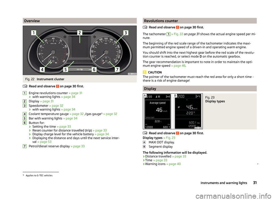
OverviewFig. 22
Instrument cluster
Read and observe
on page 30 first.
Engine revolutions counter » page 31
› with warning lights
» page 34
Display » page 31
Speedometer » page 32
› with warning lights
» page 34
Coolant temperature gauge » page 32 ,/gas gauge 1)
» page 32
Bar with warning lights » page 34
Button for:
› Setting the time
» page 33
› Reset counter for distance travelled (trip)
» page 33
› Display charge level for the vehicle battery
» page 34
› Displaying the distance and days until the next service inter-
val » page 53
Petrol/diesel reserve display » page 33
1234567Revolutions counter
Read and observe
on page 30 first.
The tachometer
1
» Fig. 22 on page 31 shows the actual engine speed per mi-
nute.
The beginning of the red scale range of the tachometer indicates the maxi-
mum permitted engine speed of a driven-in and operating warm engine.
You should shift into the next highest gear before the red scale of the revolu- tion counter is reached, or select mode D on the automatic gearbox.
The gear recommendation is important to note in order to maintain the opti-
mum engine speed » page 46.
CAUTION
The pointer of the tachometer must reach the red area for only a short time -
there is a risk of engine damage!
Display
Fig. 23
Display types
Read and observe on page 30 first.
Display types » Fig. 23
MAXI DOT display.
Segment display
The following information will be displayed.
› Distance travelled
» page 33
› Time
» page 33
› Warning icons
» page 40
1)
Applies to G-TEC vehicles
31Instruments and warning lights
Page 43 of 280
Trailer turn signal lightsRead and observe
on page 34 first.
If the warning light
flashes , the trailer turn signal lights are turned on.
If a trailer is hitched and the warning light
is not flashing , one of the trailer
turn signal lights has failed.
The following message is shown in the information cluster display, for exam-
ple.
Trailer: check left turn signal!
TRAILER TURN SIG_ CHECK LEFT
The trailer must be unhitched properly » page 169, Hitch and trailer .
Fog lights
Read and observe
on page 34 first.
The warning light
illuminates when the fog lights are operating.
Cruise control system
Read and observe
on page 34 first.
The indicator light
is illuminated when the cruise control system and auto-
matic distance control are switched on.
Brake pedal (automatic transmission)
Read and observe
on page 34 first.
If the warning light
illuminates , operate the brake pedal.
Natural gas operation
Read and observe
on page 34 first.
If the warning light
is lit, the vehicle is powered by natural gas.
Main beam
Read and observe
on page 34 first.
The warning light
illuminates when the main beam or the headlight flasher
is operated.
Warning icons in the display
Introduction
This chapter contains information on the following subjects:
Rear seat belt warning
41
Alternator
41
Coolant
41
Engine oil pressure
42
Engine oil level
42
Lamp failure
43
Diesel particulate filter (diesel engine)
43
Windscreen washer fluid level
43
Fuel reserve
43
Headlight assist
44
START-STOP-system
44
Display of a low temperature
44
Water in the fuel filter (diesel engine)
44
Adaptive Cruise Control (ACC)
44
Distance warning (Front Assistant)
44
Advance warning/emergency brake (Front Assistant)
45
The warning icons indicate the status of certain functions or faults.
The warning icons are indicated in the display of the instrument clus-
ter » page 31 .
Depending on the meaning, the symbol or
in the bar lists up simultane-
ously with the corresponding control symbol, with indicator lights
5
» Fig. 22
on page 31 .
SymbolMeaningDangerWarning 40Using the system
Page 44 of 280
While the operational faults remain unrectified, the messages are always indi-
cated again. After they are displayed for the first time, the symbols or
continue to be displayed without any extra messages for the driver.
Some warning icons can be accompanied by acoustic signals and messages in
the instrument cluster display.
After switching on the ignition, some warning icons illuminate briefly as a
function test.
If the tested systems are OK, the corresponding warning lights go out a few
seconds after switching on the ignition or after starting the engine.
The status of some features and systems is shown by the warning
lights » page 34 .
On vehicles with a colour MAXI DOT display some warning icons in the display
are in colour.WARNING■ Ignoring illuminated warning icons and related messages or instructions
in the display of the instrument cluster may lead to serious personal injury
or damage to the vehicle.■
If you have to stop for technical reasons, then park the vehicle at a safe
distance from the traffic, switch off the engine and activate the hazard
warning light system » page 77. The warning triangle must be set up at
the prescribed distance - observe the national legal provisions when doing
so.
■
The engine compartment of your car is a hazardous area. While working in
the engine compartment, be sure to observe the following warn-
ings » page 192 , Engine compartment .
Rear seat belt warning
Read and observe
on page 41 first.
A rear seat belt is not fastened
A rear seat belt is fastened
The warning icons or
light up after the ignition has been switched on.
When the seat belt is fastened/unfastened, the particular icon lights up briefly
and indicates the current belt status.
Alternator
Read and observe
on page 41 first.
The warning icon
lights up if the vehicle battery is not charged when the
engine is running.
Seek assistance from a specialist garage immediately.
CAUTION
If symbol lights up in addition to symbol while driving, stop driving -
there is a risk of engine damage! Switch off the engine and seek assistance
from a specialist garage.
Coolant
Read and observe
on page 41 first.
Coolant level too low
If the coolant level is too low, the warning icon
lights up and the following
message appears in the instrument cluster display.
Check coolant! Owner's manual!
ENGINE COOLANT PLEASE CHECK
› Stop the vehicle, switch off the engine, and check the coolant lev-
el » page 198 .
› If the coolant level is too low, add coolant to the reservoir
» page 198.
If the indicator light
does not illuminate after adding coolant and switching
on the engine, you may continue your journey.
If the coolant is within the specified range and the warning symbol is still
lit
after switching on the ignition, then there may be a malfunction of the cooling
fan.
› Switch off the ignition.
› Check the fuse for the radiator fan, replace if necessary
» page 230, Fuses in
the engine compartment .
If the coolant level and fan fuse are OK and the warning symbol
lights up
again after switching on the ignition,
do not continue driving!
Seek help from a specialist garage.
41Instruments and warning lights
Page 45 of 280
Coolant temperature too high
If the coolant temperature is too high, the warning icon lights up and the
following message appears in the instrument cluster display.
Engine overheat. Stop! Owner's manual!
ENGINE OVERHEAT STOP
› Stop the vehicle and turn off the engine.
› Switch on the ignition and wait until the coolant temperature pointer returns
to the operating range » page 32.
› Continue your journey only after the warning icon
has disappeared.WARNING■
Carefully open the coolant expansion bottle. If the engine is hot, the cool-
ing system is pressurized – risk of scalding! It is therefore best to allow the
engine to cool down before removing the cap.■
Do not touch the radiator fan. The radiator fan may switch itself on auto-
matically even if the ignition is off - risk of injury!
CAUTION
■ Additional headlights and other attached components in front of the air inlet
impair the cooling efficiency of the coolant.■
Never cover the radiator - there is a risk of the engine overheating.
Engine oil pressure
Read and observe
on page 41 first.
When the warning light
is flashing , the engine oil pressure is too low.
The following message is shown in the information cluster display. Oil pressure: Stop! Owner's manual!
STOP VEHICLE OIL PRESSURE
›
Stop the vehicle, switch off the engine, and check the level of the engine
oil » page 196 , Checking the oil level .
›
If the oil pressure is too low, top up the engine oil » page 197.
If the oil level is within the specified range and the warning symbol
starts
to flash again after the engine is started,
do not continue driving! Switch off
the engine and seek assistance from a specialist garage.
CAUTIONIf for some reason it is not possible to top up the engine oil under the current
circumstances, do not continue driving! Switch off the engine and seek as-
sistance from a specialist garage.
Engine oil level
Read and observe
on page 41 first.
Engine oil level too low
If the warning icons and
are lit , the engine oil level is too low.
The following message is shown in the information cluster display. Oil level: add oil!
ADD OIL
› Stop the vehicle, switch off the engine, and check the engine oil lev-
el » page 196 .
The warning icon will go out if the bonnet is left open for more than 30 sec-
onds. If no engine oil has been replenished, the warning icon will come on
again after driving about 100 km.
Engine oil level too high
If the warning icons and
are
lit in conjunction with the following message
on the display, the engine oil level is too high.
Reduce oil level!
OIL LEVEL TOO HIGH
› Stop the vehicle, switch off the engine, and check the engine oil lev-
el » page 196 .
Engine oil level sensor
If the warning icons and
are
lit in conjunction with the following message
on the display, the engine oil level sensor is defective.
Oil sensor: Workshop!
OIL SENSOR WORKSHOP
Seek assistance from a specialist garage immediately.
CAUTION
If for some reason it is not possible to top up the engine oil under the current
circumstances, do not continue driving! Switch off the engine and seek as-
sistance from a specialist garage.42Using the system
Page 125 of 280
CAUTION■The running auxiliary heater consumes fuel from the vehicle tank and auto-
matically controls the filling level. If only a low quantity of fuel is present in the
fuel tank, the auxiliary heating switches off.■
The exhaust pipe of the auxiliary heating, which is located on the underside
of the vehicle, must not be clogged and the exhaust flow must not be blocked.
■
If the auxiliary heating is running, the vehicle battery discharges. If the auxili-
ary heating and ventilation has been operated several times over a longer peri-
od, the vehicle must be driven a few kilometres in order to recharge the vehi-
cle battery.
■
The air inlet in front of the windscreen must be free (e.g. of ice, snow or
leaves) to ensure that the auxiliary heating operates properly.
Note
■ The auxiliary heating switches on the blower B » Fig. 125 on page 119 orC » Fig. 126 on page 119 only if it has achieved a coolant temperature of ap-
prox. 50 °C.■
At low outside temperatures, this can result in a formation of water vapour in
the area of the engine compartment. This is quite normal and is not an operat-
ing problem.
■
So that warm air can flow into the vehicle interior after switching on the aux-
iliary heating, you must maintain the comfort temperature normally selected
by you, leave the fan switched on and leave the air outlet vents in an open po-
sition. It is recommended to put the air flow in the position
or
.
Switching on/off
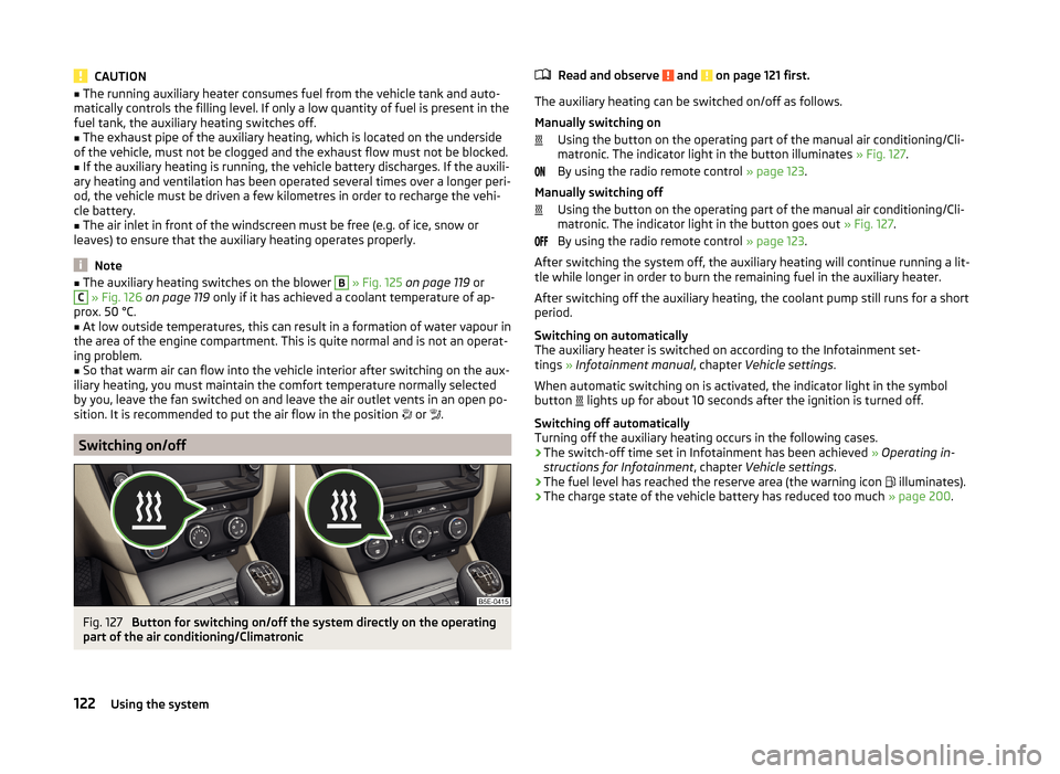
Fig. 127
Button for switching on/off the system directly on the operating
part of the air conditioning/Climatronic
Read and observe and on page 121 first.
The auxiliary heating can be switched on/off as follows.
Manually switching on Using the button on the operating part of the manual air conditioning/Cli-
matronic. The indicator light in the button illuminates » Fig. 127.
By using the radio remote control » page 123.
Manually switching off Using the button on the operating part of the manual air conditioning/Cli-
matronic. The indicator light in the button goes out » Fig. 127.
By using the radio remote control » page 123.
After switching the system off, the auxiliary heating will continue running a lit- tle while longer in order to burn the remaining fuel in the auxiliary heater.
After switching off the auxiliary heating, the coolant pump still runs for a short
period.
Switching on automatically
The auxiliary heater is switched on according to the Infotainment set-
tings » Infotainment manual , chapter Vehicle settings .
When automatic switching on is activated, the indicator light in the symbol
button lights up for about 10 seconds after the ignition is turned off.
Switching off automatically
Turning off the auxiliary heating occurs in the following cases.
› The switch-off time set in Infotainment has been achieved
» Operating in-
structions for Infotainment , chapter Vehicle settings .
› The fuel level has reached the reserve area (the warning icon
illuminates).
› The charge state of the vehicle battery has reduced too much
» page 200.
122Using the system
Page 198 of 280
NoteThe location of the inspection points in the engine compartment of petrol and
diesel engines is practically identical.
Radiator fan
Read and observe
and on page 193 first.
The radiator fan is powered by an electric motor. Operation is controlled ac-
cording to the temperature of the coolant.
WARNINGAfter switching off the ignition, the fan can intermittently continue to oper-
ate for approx. 10 minutes.
Windscreen washer system
Fig. 186
Windscreen washer fluid reser-
voir
Read and observe and on page 193 first.
The windscreen washer fluid reservoir
A
is located in the engine compart-
ment » Fig. 186 .
The cleaning fluid is provided for the cleaning of the front and rear window as
well as the headlight.
The capacity of the reservoir is about 3 litres or about 4.7 litres on vehicles that
have a headlight cleaning system 1)
.
Clear water is not sufficient to intensively clean the windscreen and head-
lights. We recommend using clean washing water together with the screen
cleaner from the range of ŠKODA Original Accessories (in winter additionally
with antifreeze) which is capable of removing stubborn dirt.
In Winter, the washing water should always be mixed with antifreeze even if
the vehicle has heated windscreen washer nozzles.
Under exceptional circumstances, methylated spirits can also be used if no
screen cleaner with antifreeze is available. The concentration of methylated
spirits must not be more than 15 %. The freeze protection at this concentration
is sufficient only to -5 °C.
CAUTION
■ Under no circumstances must radiator antifreeze or other additives be added
to the windscreen washer fluid.■
If the vehicle is fitted with a headlight cleaning system, only cleaning prod-
ucts which do not attack the polycarbonate coating of the headlights must be
added to the windscreen washer fluid.
■
Do not remove the filter from the windscreen washer fluid reservoir when re-
plenishing it with liquid otherwise the liquid transportation system can be con-
taminated, which can cause the windscreen washer system to malfunction.
Engine oil
Introduction
This chapter contains information on the following subjects:
Specification
196
Checking the oil level
196
Replenishing
197
The engine has been factory-filled with a high-grade oil that can be use
throughout the year - except in extreme climate zones.
The engine oils are undergoing continuous further development. Thus the in- formation stated in this Owner's Manual is only correct at the time of publica-
tion.
1)
In some countries, 4.7 ltr. applies for both variants.
195Inspecting and replenishing
Page 200 of 280
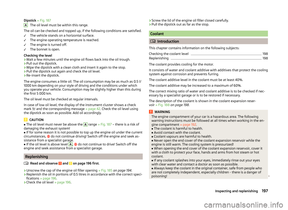
Dipstick » Fig. 187
The oil level must be within this range.
The oil can be checked and topped up, if the following conditions are satisfied. The vehicle stands on a horizontal surface.
The engine operating temperature is reached.
The engine is turned off.
The bonnet is open.
Checking the level›
Wait a few minutes until the engine oil flows back into the oil trough.
›
Pull out the dipstick.
›
Wipe the dipstick with a clean cloth and insert it again to the stop.
›
Pull the dipstick out again and check the oil level.
›
Re-insert the dipstick.
The engine consumes a little oil. The oil consumption may be as much as 0.5 l/
1000 km depending on your style of driving and the conditions under which
you operate your vehicle. Consumption may be slightly higher than this during
the first 5 000 km.
The oil level must be checked at regular intervals.
In case of low oil level, the display of the instrument cluster shows a check
mark and the corresponding message
» page 42. Check the oil level using
the dipstick as soon as possible. Add oil accordingly.
CAUTION
■ The oil level must never be above the A range » Fig. 187 – there is a risk of
damaging the exhaust system!■
If for some reason it is not possible to top up the engine oil under the current
circumstances,
do not continue driving! Switch off the engine and seek as-
sistance from a specialist garage.
■
If the oil level is above level
A
,
do not continue to drive! Switch off the
engine and seek assistance from a specialist garage.
Replenishing
Read and observe
and on page 196 first.
›
Unscrew the cap of the engine oil filler opening » Fig. 185 on page 194 .
›
Replenish the oil in portions of 0.5 litres in accordance with the correct speci-
fications » page 196 .
›
Check the oil level » page 196.
A›Screw the lid of the engine oil filler closed carefully.›Pull the dipstick out as far as the stop.
Coolant
Introduction
This chapter contains information on the following subjects:
Checking the coolant level
198
Replenishing
198
The coolant provides cooling for the motor.
It consists of water and coolant additive with additives that protect the cooling
system against corrosion and prevents furring.
The coolant additive level in the coolant must be at least 40%.
The coolant additive may be increased to a maximum of 60%.
The correct mixing ratio of water and coolant additive is to be checked if nec- essary by a specialist garage or is to be restored if necessary.
The description of the coolant is shown in the coolant expansion reser-
voir » Fig. 188 on page 198 .
WARNINGThe engine compartment of your car is a hazardous area. The following
warning instructions must be followed at all times when working in the en- gine compartment » page 192.■
The coolant is harmful to health.
■
Avoid contact with the coolant.
■
Coolant vapours are harmful to health.
■
Never open the end cover of the coolant expansion reservoir while the
engine is still warm. The cooling system is pressurized!
■
When opening the end cover of the coolant expansion reservoir, cover it
with a cloth to protect your face, hands and arms from hot steam or hot
coolant.
■
If any coolant splashes into your eyes, immediately rinse out your eyes
with clear water and contact a doctor as soon as possible.
■
Always keep the coolant in the original container, safe from people who
are not completely independent, especially children - there is a danger of
poisoning!
197Inspecting and replenishing
Page 201 of 280
WARNING (Continued)■If coolant is swallowed, consult a doctor immediately.■Never spill operating fluids over the hot engine - risk of fire.
CAUTION
■If for some reason it is not possible to top up the coolant under the current
circumstances, do not continue driving! Switch off the engine and seek as-
sistance from a specialist garage.■
If the expansion tank is empty, do not top up with coolant. The system could
aerate - risk of engine damage,
do not continue driving! Switch off the en-
gine and seek assistance from a specialist garage.
■
The amount of coolant additive in the coolant must never be allowed to be
less than 40 %.
■
Over 60 % of coolant additive in the coolant reduces the antifreeze protec-
tion and coolant effectiveness.
■
A coolant additive that does not comply with the correct specification can
significantly reduce the corrosion protection of the cooling system.
■
Any faults resulting from corrosion may cause a loss of coolant and can con-
sequently result in major engine damage!
■
Do not fill the coolant above the mark
A
» Fig. 188 on page 198 .
■
If an error occurs, leading to the engine overheating, the help of a professio-
nal garage is to be sought - there is a risk of serious engine damage occurring.
■
Additional headlights and other attached components in front of the air inlet
impair the cooling efficiency of the coolant.
■
Never cover the radiator - there is a risk of the engine overheating.
Note
On vehicles that are fitted with an auxiliary heater (auxiliary heating and venti-
lation), the coolant capacity is approx. 1 l larger.
Checking the coolant level
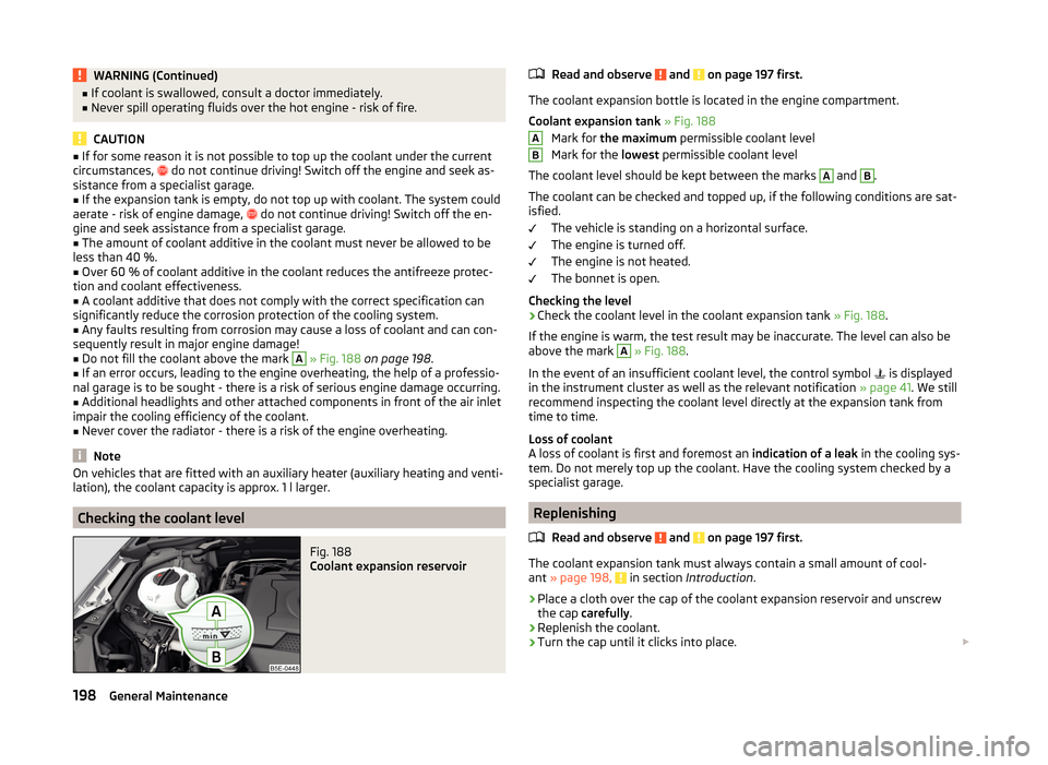
Fig. 188
Coolant expansion reservoir
Read and observe and on page 197 first.
The coolant expansion bottle is located in the engine compartment.
Coolant expansion tank » Fig. 188
Mark for the maximum permissible coolant level
Mark for the lowest permissible coolant level
The coolant level should be kept between the marks
A
and
B
.
The coolant can be checked and topped up, if the following conditions are sat-
isfied.
The vehicle is standing on a horizontal surface.
The engine is turned off.
The engine is not heated.
The bonnet is open.
Checking the level
›
Check the coolant level in the coolant expansion tank » Fig. 188.
If the engine is warm, the test result may be inaccurate. The level can also be
above the mark
A
» Fig. 188 .
In the event of an insufficient coolant level, the control symbol is displayed
in the instrument cluster as well as the relevant notification » page 41. We still
recommend inspecting the coolant level directly at the expansion tank from
time to time.
Loss of coolant
A loss of coolant is first and foremost an indication of a leak in the cooling sys-
tem. Do not merely top up the coolant. Have the cooling system checked by a
specialist garage.
Replenishing
Read and observe
and on page 197 first.
The coolant expansion tank must always contain a small amount of cool-
ant » page 198, in section Introduction .
›
Place a cloth over the cap of the coolant expansion reservoir and unscrew
the cap carefully .
›
Replenish the coolant.
›
Turn the cap until it clicks into place.
AB198General Maintenance