display SKODA OCTAVIA 2014 3.G / (5E) Owner's Manual
[x] Cancel search | Manufacturer: SKODA, Model Year: 2014, Model line: OCTAVIA, Model: SKODA OCTAVIA 2014 3.G / (5E)Pages: 280, PDF Size: 35.53 MB
Page 5 of 280
Table of Contents
On-board literature4
Notes
5
Structure and more information about the
Owner's manual
6
Abbreviations
Safety
Passive Safety
8
General information
8
Correct and safe seated position
9
Seat belts
12
Using seat belts
12
Inertia reel and belt pretensioners
15
Airbag system
16
Description of the airbag system
16
Airbag overview
17
Deactivating airbags
21
Transporting children safely
22
Child seat
22
Fastening elements
25
Using the system
Cockpit
29
Overview
28
Instruments and warning lights
30
Instrument cluster
30
Warning lights
34
Warning icons in the display
40
Information system
45
Driver information system
45
Driving data (Multifunction display)
47MAXI DOT display50Service interval display53
Unlocking and opening
54
Unlocking and locking
54
Anti-theft alarm system
59
Luggage compartment lid
60
Electric boot lid
61
Power windows
64
Mechanical windows
66
Panorama sliding-/tilting roof - Version 1
67
Panorama sliding-/tilting roof - Version 2
68
Lights and visibility
71
Lights
71
Interior lights
78
Visibility
80
Windscreen wipers and washers
81
Rear mirror
83
Seats and head restraints
86
Seats and head restraints
86
Seat features
90
Transporting and practical equipment
94
Useful equipment
94
Luggage compartment
103
Variable loading floor in the luggage
compartment (Estate)
110
Net partition
112
Roof rack
113
Heating and air conditioning
116
Heating, ventilation, cooling
116
Auxiliary heating (auxiliary heating and
ventilation)
121
Communication
124
SmartGate
124Driving
Starting-off and Driving126
Starting and stopping the engine using the key
126
Starting or stopping the engine by pressing
button
128
Brakes and parking
130
Manual shifting of gears and pedals
132
Automatic gearbox
133
Retraction and economical driving
136
Driving through water and driving off of
made-up roads
137
Assist systems
138
Braking and stabilisation systems
138
Parking aid
140
Optical Parking Assistant (rear view camera)
143
Park assist
144
Cruise Control System
148
Adaptive Cruise Control (ACC)
149
Front Assistant
155
START-STOP
158
Selection of travel mode (Driving Mode
Selection)
160
ProActive passenger protection
161
Lane Assist
162
Traffic sign recognition
164
Fatigue detection (break recommendation)
166
Tyre pressure monitoring
167
Hitch and trailer
169
Hitch
169
Trailer
1742Table of Contents
Page 8 of 280
Notes
Terms used
The on-board literature contains the following terms relating to the service
work for your vehicle. - Workshop - a workshop that carries out specialist service tasks
for ŠKODA vehicles. A specialist can be a ŠKODA Partner, a ŠKODA Serv-
ice Partner, or an independent workshop.
- A Workshop that has been contractually authorized
by the manufacturer ŠKODA AUTO a.s. or its sales partner to perform
service tasks on ŠKODA vehicles and to sell ŠKODA Genuine Parts.
- A company that has been authorized by the manufacturer
ŠKODA AUTO a.s. or its sales partner to sell new ŠKODA vehicles and, when applicable, to service them using ŠKODA Genuine Parts and sell
ŠKODA Genuine Parts.
Explanation of symbols
An overview of the symbols used in the Owner's manual and a brief explana-
tion of their meanings.Reference to the introductory module of a chapter with important infor-
mation and safety warnings.Continuation of the module on the next page.Situations where the vehicle must be stopped as soon as possible.®Registered trademark.Text display in the MAXI DOT display.Text display in the segment display.WARNINGTexts with this symbol draw attention to threats of a serious accident, in-
jury or loss of life .
CAUTION
Texts with this symbol draw attention to the risk of vehicle damage or possible
inoperability of some systems.
For the sake of the environment
Texts with this symbol contain information on environmental protection as
well as tips for economical operation.“Specialist”“ŠKODA Service Partner”“ŠKODA Partner”NoteTexts with this symbol contain additional information.5Notes
Page 9 of 280
Structure and more information about the Owner's
manual
Structure of the manual
The Owner's manual is hierarchically divided into the following areas.
■ Section (e.g. Safety) - the title of the Section is always indicated at the lower
left-hand side
■ Main chapter (e.g. Airbag system) - the title of the main chapter is always
indicated at the lower right-hand side
■ Chapter (e.g. Airbag overview)
■ Introduction to the topic
- Module overview within the chapter, in-
troductory information about the chapter content, any necessary infor-
mation applicable to the entire chapter
■ Module (e.g. Front airbags)
Information search
When searching for information in the manual, we recommend using the Index
at the end of the manual.
Direction indications
All direction indications such as “left”, “right”, “front” and “rear” relate to the forward direction of travel of the vehicle.
Units of measurement
The volume, weight, speed and length data is given in metric units, unless oth-
erwise indicated.
Display
In this Owner's manual, the screen on the MAXI DOT display is used as the dis-
play illustration, unless specified otherwise.6Structure and more information about the Owner's manual
Page 23 of 280
WARNING■The airbag control unit operates using pressure sensors located in the
front doors. For this reason, no adjustments may be carried out to the
doors or door panels (e.g. the installation of additional loudspeakers). Fur-
ther information » page 179, Airbags .■
Ensure that there are no excessive forces, such as violent knocks, kicks
etc., impact on the backrests of the seats otherwise the system may be
damaged. The side airbags would not be deployed in such a case!
■
Any seat or protective covers which you fit to the driver or front passen-
ger seats must only be of the type expressly authorized by ŠKODA. In view
of the fact that the airbag inflates out of the backrest of the seat, use of
non-approved seat or protective covers would considerably impair the pro-
tective function of the side airbag.
■
Any damage to the original seat covers in the area of the side airbag mod-
ule must be repaired immediately by a specialist garage.
■
The airbag modules in the front seats must not display any damage,
cracks or deep scratches. It is not permissible to use force in order to open
the modules.
Note
■ In vehicles with side front airbags, a label with the text is located on
the front seat backrests.■
In vehicles with rear side airbags, the text
can be seen between the en-
trance area and the rear seat rest.
Head airbags
Fig. 13
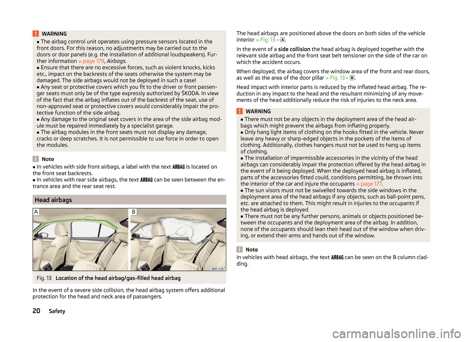
Location of the head airbag/gas-filled head airbag
In the event of a severe side collision, the head airbag system offers additional
protection for the head and neck area of passengers.
The head airbags are positioned above the doors on both sides of the vehicle
interior » Fig. 13 - .
In the event of a side collision the head airbag is deployed together with the
relevant side airbag and the front seat belt tensioner on the side of the car on
which the accident occurs.
When deployed, the airbag covers the window area of the front and rear doors,
as well as the area of the door pillar » Fig. 13 -
.
Head impact with interior parts is reduced by the inflated head airbag. The re-
duction in any impact to the head and the resultant minimizing of any move-
ments of the head additionally reduce the risk of injuries to the neck area.WARNING■ There must not be any objects in the deployment area of the head air-
bags which might prevent the airbags from inflating properly.■
Only hang light items of clothing on the hooks fitted in the vehicle. Never
leave any heavy or sharp-edged objects in the pockets of the items of
clothing. Additionally, clothes hangers must not be used to hang up items
of clothing.
■
The installation of impermissible accessories in the vicinity of the head
airbags can considerably impair the protection offered by the head airbag in
the event of it being deployed. When the deployed head airbag is inflated,
parts of the accessories fitted could, conditions permitting, be thrown into
the interior of the car and injure the occupants » page 177.
■
The sun visors must not be swivelled towards the side windows in the
deployment area of the head airbags if any objects, such as ball-point pens,
etc. are attached to them. This might result in injuries to the occupants if
the head airbag is deployed.
■
There must not be any further persons, animals or objects positioned be-
tween the occupants and the deployment area of the airbag. In addition,
none of the occupants should lean their head out of the window when driv-
ing, or extend their arms and hands out of the window.
Note
In vehicles with head airbags, the text can be seen on the B column clad-
ding.20Safety
Page 32 of 280
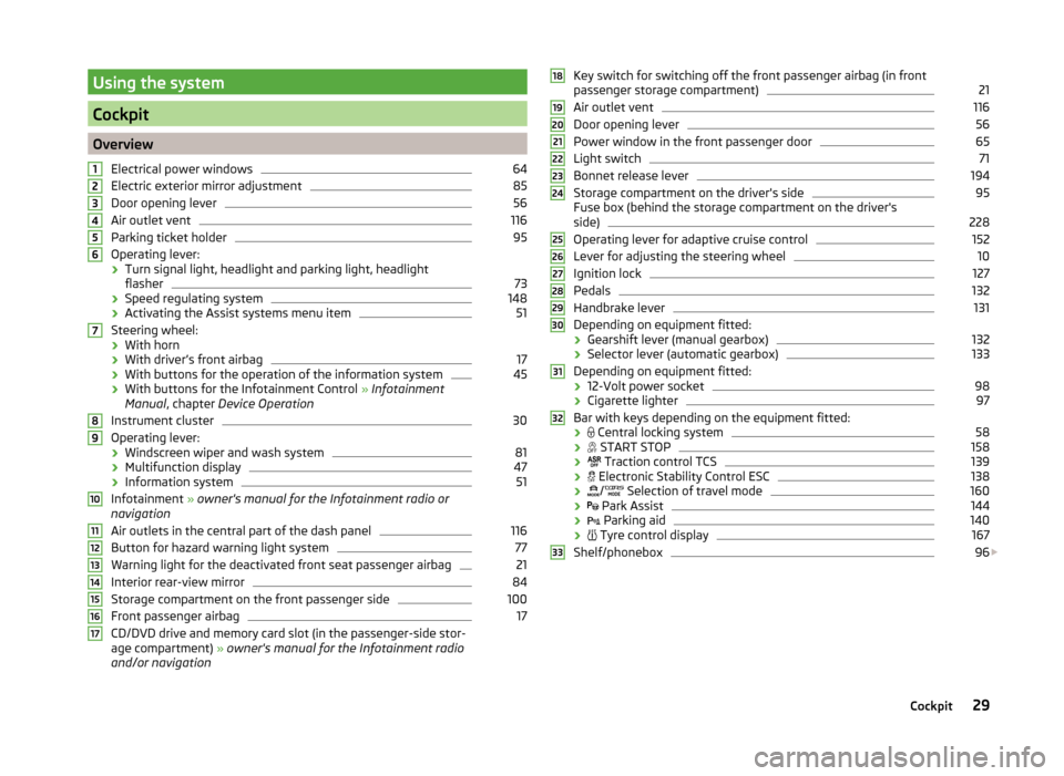
Using the system
Cockpit
OverviewElectrical power windows
64
Electric exterior mirror adjustment
85
Door opening lever
56
Air outlet vent
116
Parking ticket holder
95
Operating lever:
› Turn signal light, headlight and parking light, headlight
flasher
73
› Speed regulating system
148
›Activating the Assist systems menu item
51
Steering wheel:
› With horn
› With driver’s front airbag
17
›With buttons for the operation of the information system
45
›With buttons for the Infotainment Control
» Infotainment
Manual , chapter Device Operation
Instrument cluster
30
Operating lever: › Windscreen wiper and wash system
81
›Multifunction display
47
›Information system
51
Infotainment
» owner's manual for the Infotainment radio or
navigation
Air outlets in the central part of the dash panel
116
Button for hazard warning light system
77
Warning light for the deactivated front seat passenger airbag
21
Interior rear-view mirror
84
Storage compartment on the front passenger side
100
Front passenger airbag
17
CD/DVD drive and memory card slot (in the passenger-side stor-
age compartment) » owner's manual for the Infotainment radio
and/or navigation
1234567891011121314151617Key switch for switching off the front passenger airbag (in front
passenger storage compartment)21
Air outlet vent
116
Door opening lever
56
Power window in the front passenger door
65
Light switch
71
Bonnet release lever
194
Storage compartment on the driver's side
95
Fuse box (behind the storage compartment on the driver's
side)
228
Operating lever for adaptive cruise control
152
Lever for adjusting the steering wheel
10
Ignition lock
127
Pedals
132
Handbrake lever
131
Depending on equipment fitted:
› Gearshift lever (manual gearbox)
132
›Selector lever (automatic gearbox)
133
Depending on equipment fitted:
› 12-Volt power socket
98
›Cigarette lighter
97
Bar with keys depending on the equipment fitted:
›
Central locking system
58
›
START STOP
158
›
Traction control TCS
139
›
Electronic Stability Control ESC
138
›
/
Selection of travel mode
160
›
Park Assist
144
›
Parking aid
140
›
Tyre control display
167
Shelf/phonebox
96
1819202122232425262728293031323329Cockpit
Page 33 of 280
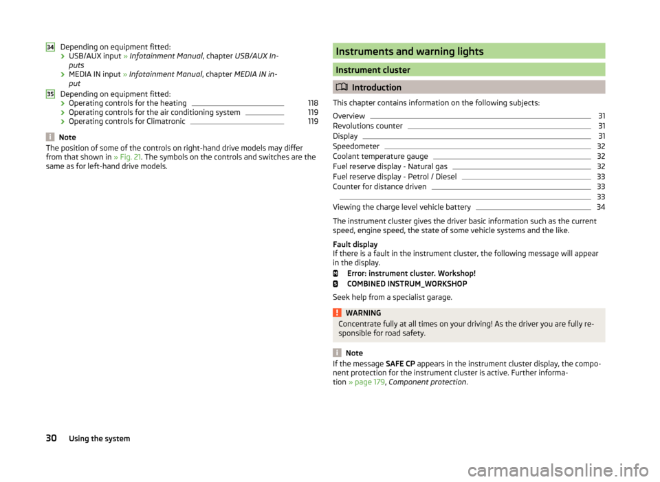
Depending on equipment fitted:› USB/AUX input
» Infotainment Manual , chapter USB/AUX In-
puts
› MEDIA IN input
» Infotainment Manual , chapter MEDIA IN in-
put
Depending on equipment fitted: › Operating controls for the heating118
›Operating controls for the air conditioning system
119
›Operating controls for Climatronic
119
Note
The position of some of the controls on right-hand drive models may differ
from that shown in » Fig. 21. The symbols on the controls and switches are the
same as for left-hand drive models.3435Instruments and warning lights
Instrument cluster
Introduction
This chapter contains information on the following subjects:
Overview
31
Revolutions counter
31
Display
31
Speedometer
32
Coolant temperature gauge
32
Fuel reserve display - Natural gas
32
Fuel reserve display - Petrol / Diesel
33
Counter for distance driven
33
33
Viewing the charge level vehicle battery
34
The instrument cluster gives the driver basic information such as the current
speed, engine speed, the state of some vehicle systems and the like.
Fault display
If there is a fault in the instrument cluster, the following message will appear
in the display.
Error: instrument cluster. Workshop!
COMBINED INSTRUM_WORKSHOP
Seek help from a specialist garage.
WARNINGConcentrate fully at all times on your driving! As the driver you are fully re-
sponsible for road safety.
Note
If the message SAFE CP appears in the instrument cluster display, the compo-
nent protection for the instrument cluster is active. Further informa-
tion » page 179 , Component protection .30Using the system
Page 34 of 280
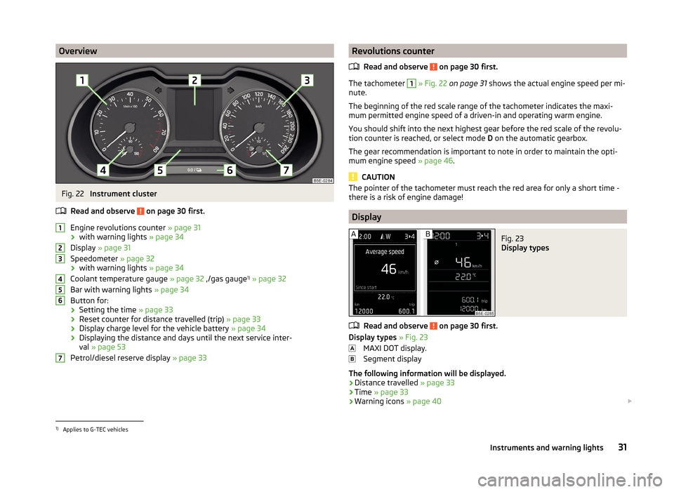
OverviewFig. 22
Instrument cluster
Read and observe
on page 30 first.
Engine revolutions counter » page 31
› with warning lights
» page 34
Display » page 31
Speedometer » page 32
› with warning lights
» page 34
Coolant temperature gauge » page 32 ,/gas gauge 1)
» page 32
Bar with warning lights » page 34
Button for:
› Setting the time
» page 33
› Reset counter for distance travelled (trip)
» page 33
› Display charge level for the vehicle battery
» page 34
› Displaying the distance and days until the next service inter-
val » page 53
Petrol/diesel reserve display » page 33
1234567Revolutions counter
Read and observe
on page 30 first.
The tachometer
1
» Fig. 22 on page 31 shows the actual engine speed per mi-
nute.
The beginning of the red scale range of the tachometer indicates the maxi-
mum permitted engine speed of a driven-in and operating warm engine.
You should shift into the next highest gear before the red scale of the revolu- tion counter is reached, or select mode D on the automatic gearbox.
The gear recommendation is important to note in order to maintain the opti-
mum engine speed » page 46.
CAUTION
The pointer of the tachometer must reach the red area for only a short time -
there is a risk of engine damage!
Display
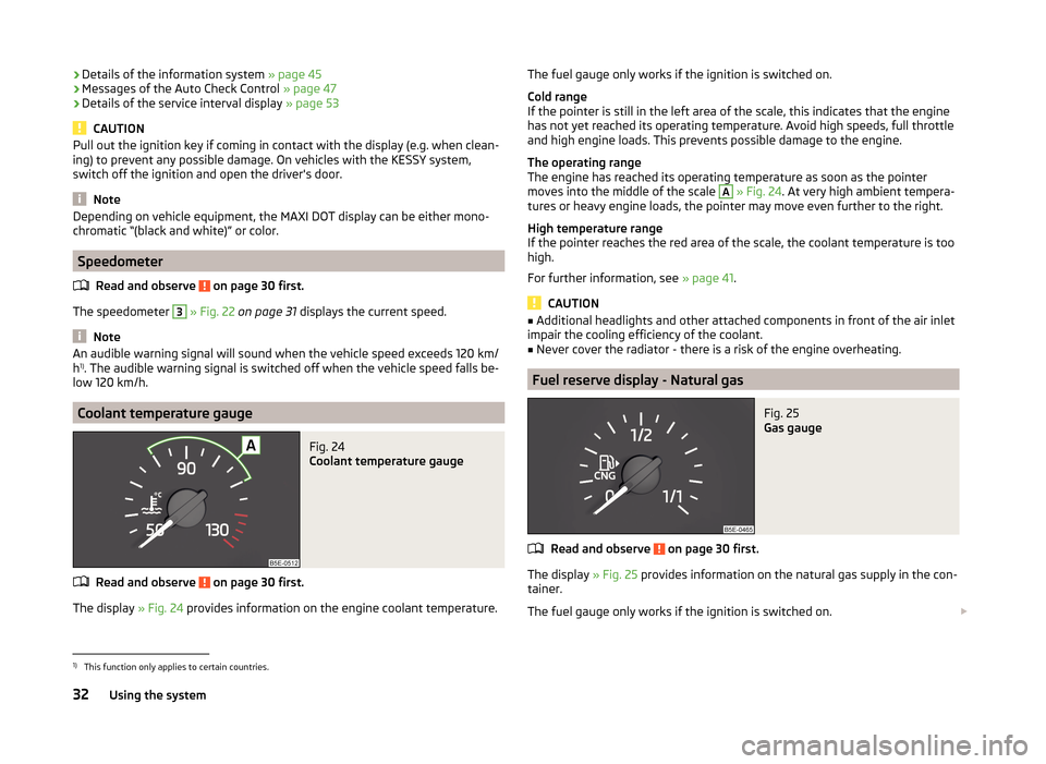
Fig. 23
Display types
Read and observe on page 30 first.
Display types » Fig. 23
MAXI DOT display.
Segment display
The following information will be displayed.
› Distance travelled
» page 33
› Time
» page 33
› Warning icons
» page 40
1)
Applies to G-TEC vehicles
31Instruments and warning lights
Page 35 of 280
›Details of the information system
» page 45
› Messages of the Auto Check Control
» page 47
› Details of the service interval display
» page 53
CAUTION
Pull out the ignition key if coming in contact with the display (e.g. when clean-
ing) to prevent any possible damage. On vehicles with the KESSY system,
switch off the ignition and open the driver's door.
Note
Depending on vehicle equipment, the MAXI DOT display can be either mono-
chromatic “(black and white)” or color.
Speedometer
Read and observe
on page 30 first.
The speedometer
3
» Fig. 22 on page 31 displays the current speed.
Note
An audible warning signal will sound when the vehicle speed exceeds 120 km/
h 1)
. The audible warning signal is switched off when the vehicle speed falls be-
low 120 km/h.
Coolant temperature gauge
Fig. 24
Coolant temperature gauge
Read and observe on page 30 first.
The display » Fig. 24 provides information on the engine coolant temperature.
The fuel gauge only works if the ignition is switched on.
Cold range
If the pointer is still in the left area of the scale, this indicates that the engine
has not yet reached its operating temperature. Avoid high speeds, full throttle
and high engine loads. This prevents possible damage to the engine.
The operating range
The engine has reached its operating temperature as soon as the pointer
moves into the middle of the scale A
» Fig. 24 . At very high ambient tempera-
tures or heavy engine loads, the pointer may move even further to the right.
High temperature range
If the pointer reaches the red area of the scale, the coolant temperature is too
high.
For further information, see » page 41.
CAUTION
■
Additional headlights and other attached components in front of the air inlet
impair the cooling efficiency of the coolant.■
Never cover the radiator - there is a risk of the engine overheating.
Fuel reserve display - Natural gas
Fig. 25
Gas gauge
Read and observe on page 30 first.
The display » Fig. 25 provides information on the natural gas supply in the con-
tainer.
The fuel gauge only works if the ignition is switched on.
1)
This function only applies to certain countries.
32Using the system
Page 36 of 280

If the natural gas supply in the container reaches the reserve area, the icon ap-
pears in the display together with the following message.
Please refuel with CNG. Range: ... km
An audible signal sounds as a warning signal.
Fuel reserve display - Petrol / Diesel
Fig. 26
Gasoline / diesel reserve display
Read and observe on page 30 first.
The display » Fig. 26 provides information of the petrol / diesel supply in the
container.
The display only works if the ignition is switched on.
The contents of the fuel tank for petrol / diesel is approximately 50 litres.
If the amount of fuel reaches the reserve area (the pointer reaches the red
scale range), the indicator symbol
» page 43 illuminates too.
CAUTION
Never drive until the fuel tank is completely empty! The irregular supply of fuel
can cause misfiring. This can result in considerable damage to parts of the en-
gine and the exhaust system.
Note
■ After filling up, it can occur that during dynamic driving (e.g. numerous
curves, braking, driving downhill and climbing a steep hill) the fuel gauge indi-
cates approx. a fraction less. When stopping or during less dynamic driving, the
fuel gauge displays the correct fuel level again. This is not a fault.■
The arrow
next to the icon
within the fuel gauge displays the installation
location of the fuel filler on the right side of the vehicle.
Counter for distance drivenFig. 27
Display: MAXI DOT display / Seg-
ment Display
Read and observe on page 30 first.
Display » Fig. 27
Counter for distance travelled (trip)
Odometer
Counter for distance travelled (trip)
The daily trip counter shows the distance driven since the time the counter
was last reset - in steps of 100 m.
Reset counter for distance travelled (trip)
›
Briefly press the button
6
» Fig. 22 on page 31 .
Odometer
The odometer indicates the total distance which the vehicle has been driven.
Read and observe on page 30 first.
›
Switch on the ignition.
›
Press and hold the button
6
» Fig. 22 on page 31 until the Time is shown in
the display.
›
Release the button
6
, and the system switches to the time setting function.
›
Press the button
6
again and set the hours.
›
Wait around 4 seconds - the system switches to the minutes setting.
›
Press the button
6
again and set the minutes.
›
Wait around 4 seconds - the system switches to the minutes setting.
The time can also be set in the Infotainment » operating instructions for Info-
tainment , chapter Device settings .
AB33Instruments and warning lights
Page 37 of 280
Viewing the charge level vehicle batteryRead and observe
on page 30 first.
›
Switch off the ignition.
›
Press and hold the button
6
» Fig. 22 on page 31 until the Battery status or
BATTERY SOC is shown in the display.
›
Release button
6
- the current charge level 1)
of the vehicle battery is dis-
played in %.
›
Wait about 4 seconds or press the
6
key, the system returns to the home
setting.
Warning lights
Introduction
This chapter contains information on the following subjects:
Automatic Transmission
35
Handbrake
35
Brake system
35
Seat belt warning light
36
Adaptive Cruise Control (ACC)
36
Central warning light
36
Power steering/steering lock (KESSY system)
36
Traction Control System (ASR)
37
Traction control system (TCS) deactivated
37
Electronic Stability Control (ESC)
37
Antilock brake system (ABS)
37
Rear fog light
38
Exhaust inspection system
38
Glow plug system (diesel engine)
38
Engine performance check (petrol engine)
38
Security systems
38
Tyre pressure
39
Brake linings
39
Lane following system (Lane Assist)
39
Turn signal system
39
Trailer turn signal lights40 Fog lights40
Cruise control system
40
Brake pedal (automatic transmission)
40
Natural gas operation
40
Main beam
40
The warning lights indicate certain functions or faults.
Some warning lights can be accompanied by acoustic signals and messages in
the display of the instrument cluster.
After switching on the ignition, some warning lights light up briefly as a func-
tion test.
If the tested systems are OK, the corresponding warning lights go out a few
seconds after switching on the ignition or after starting the engine.
The condition of some features and systems is shown by the warning icons on
the display » page 40.
The warning lights are at the following locations in the instrument clus-
ter » Fig. 22 on page 31 .
› Revolutions counter
1
›Speedometer
3
›Bar with warning lights
5WARNING■
Ignoring illuminated warning lights and related messages or instructions
in the display of the instrument cluster may lead to serious personal injury
or damage to the vehicle.■
If you have to stop for technical reasons, then park the vehicle at a safe
distance from the traffic, switch off the engine and activate the hazard
warning light system » page 77. The warning triangle must be set up at
the prescribed distance - observe the national legal provisions when doing
so.
■
The engine compartment of your car is a hazardous area. While working in
the engine compartment, be sure to observe the following warn-
ings » page 192 , Engine compartment .
1)
Applies to vehicles with START-STOP system.
34Using the system