headlamp SKODA OCTAVIA 2014 3.G / (5E) Owner's Manual
[x] Cancel search | Manufacturer: SKODA, Model Year: 2014, Model line: OCTAVIA, Model: SKODA OCTAVIA 2014 3.G / (5E)Pages: 280, PDF Size: 35.53 MB
Page 76 of 280

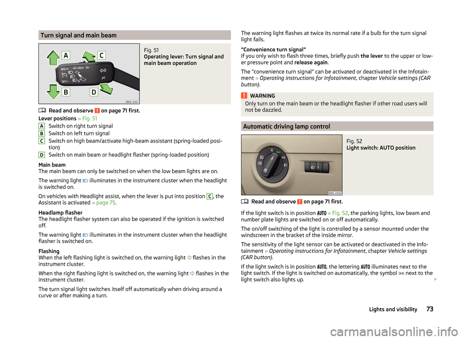
Turn signal and main beamFig. 51
Operating lever: Turn signal and
main beam operation
Read and observe on page 71 first.
Lever positions » Fig. 51
Switch on right turn signal
Switch on left turn signal
Switch on high beam/activate high-beam assistant (spring-loaded posi-
tion)
Switch on main beam or headlight flasher (spring-loaded position)
Main beam
The main beam can only be switched on when the low beam lights are on.
The warning light illuminates in the instrument cluster when the headlight
is switched on.
On vehicles with Headlight assist, when the lever is put into position
C
, the
Assistant is activated » page 75.
Headlamp flasher
The headlight flasher system can also be operated if the ignition is switched
off.
The warning light illuminates in the instrument cluster when the headlight
flasher is switched on.
Flashing
When the left flashing light is switched on, the warning light flashes in the
instrument cluster.
When the right flashing light is switched on, the warning light flashes in the
instrument cluster.
The turn signal light switches itself off automatically when driving around a
curve or after making a turn.
ABCDThe warning light flashes at twice its normal rate if a bulb for the turn signal
light fails.
“Convenience turn signal”
If you only wish to flash three times, briefly push the lever to the upper or low-
er pressure point and release again.
The “convenience turn signal” can be activated or deactivated in the Infotain- ment » Operating instructions for Infotainment , chapter Vehicle settings (CAR
button) .WARNINGOnly turn on the main beam or the headlight flasher if other road users will
not be dazzled.
Automatic driving lamp control
Fig. 52
Light switch: AUTO position
Read and observe on page 71 first.
If the light switch is in position
» Fig. 52 , the parking lights, low beam and
number plate lights are switched on or off automatically.
The on/off switching of the light is controlled by a sensor mounted under the
windscreen in the bracket of the inside mirror.
The sensitivity of the light sensor can be activated or deactivated in the Info-
tainment » Operating instructions for Infotainment , chapter Vehicle settings
(CAR button) .
If the light switch is in position
, the lettering
illuminates next to the
light switch. If the light is switched on automatically, the symbol
next to the
light switch also lights up.
73Lights and visibility
Page 86 of 280

Automatic windscreen wiping in rain can be activated or deactivated in the In-
fotainment » Operating instructions for Infotainment , chapter Vehicle settings
(CAR button) .
Automatic wiping/washing for the windscreen
The wash system operates immediately, the windscreen wipers wipe some- what later. The wash system and the windscreen wiper operate simultaneous-
ly at a speed of more than 120 km/h.
Letting go of the operating lever will cause the windscreen wash system to
stop and the wipers to continue for another 2-3 wiper strokes (depending on
the spraying duration).
At a speed of more than 2 km/h, the wiper wipes once again 5 seconds after
the last wiper stroke in order to wipe the last drops from the windscreen. This
function can be activated/deactivated by a specialist garage.
Automatic wiping/washing for the rear window
The wash system operates immediately, the windscreen wiper wipes some-
what later.
Letting go of the operating lever will cause the windscreen wash system to
stop and the wiper to continue for another 2-3 wiper strokes (depending on
the spraying duration). The operating lever remains in position 6
.
Automatic rear window wiping
If the lever is in position
2
or
3
» Fig. 63 , the rear window is wiped every
30 or 10 seconds if the vehicle's speed exceeds 5 km/h.
If automatic windscreen wiping in rain is activated (the operating lever is in the position
1
) the function is only active if the windscreen wipers operate in
continuous mode (no break between each wiping process).
Automatic rear window wiping can be activated or deactivated in the Infotain-
ment » Operating instructions for Infotainment , chapter Vehicle settings (CAR
button) .
Winter setting of the windscreen wiper
If the windscreen wipers are in rest position, they cannot be folded out from
the windscreen. For this reason we recommend adjusting the windscreen wip-
ers in winter so that they can be folded out from the windscreen easily.
› Switch on the windscreen wipers.
› Switch off the ignition.
The windscreen wipers remain in the position in which they were when
switching off the ignition.
The service position can also be used as a winter position » page 227.
Note
■
If the operating lever is in the position 2 or 3 and the speed of the vehicle
drops below 4 km / h, the wiping speed is switched to a lower wiping level.
The original setting is restored step by step when the speed of the vehicle ex-
ceeds 8 km/h.■
The rear window is wiped once automatically if the windscreen wipers are on
when reverse gear is selected.
Headlight cleaning system
Read and observe
and on page 81 first.
After the ignition is switched on, the headlights are always cleaned at the first
and after every tenth spray of the windscreen (setting
5
» Fig. 63 on
page 82 ), when the low beam or main beam is switched on.
You should manually remove stubborn dirt (such as insect residues) from the headlight lenses at regular intervals, for example after refuelling. The follow-
ing guidelines must be observed » page 184, Headlight glasses .
To ensure the proper operation of the cleaning system during the winter, any snow should be removed from the washer nozzle fixtures and ice should be
cleared with a de-icing spray.
CAUTION
Never remove the nozzles from the headlight cleaning system by hand – risk of
damage!
Note
The headlamp cleaning system works with an ambient temperature of about
-12 ° C to + 39 ° C.
Rear mirror
Introduction
This chapter contains information on the following subjects:
Interior mirror
84
Exterior mirrors
85
83Lights and visibility
Page 233 of 280

No.Consumer12Radio13Belt tensioner - driver's side14Air blower for air conditioning,heating15Electric steering lock16Signal amplifier for telephone, telephone preinstallation17Instrument cluster18Not assigned19KESSY control unit20Operating lever underneath the steering wheel21Not assigned22Towing hitch - contact in the socket23Light - right24Panorama roof25Control unit for central locking front door right, power windows -
left26Heated front seats27Music amplifier28Towing hitch - left light29CNG relay30Not assigned31Headlight - left32Parking aid (Park Assist)33Airbag switch for hazard warning lights
34
TCS, ESC button, tyre control display, pressure sensor for air-condi-
tioning, reverse light switch, interior mirror with automatic dim-
ming, START-STOP button, telephone preinstallation, control for
heating of rear seats, sensor for air-conditioning, 230 V power
socket, sport-sound generator35Headlight, headlamp beam adjustment, diagnostic connector, cam-
era, radar36Headlight right37Headlight left38Towing hitch - right lightNo.Consumer39Control unit for central locking front door - right, power windows -
front and rear right4012-Volt power socket41Not assigned42Control unit for central locking rear door - left, right, headlight
cleaning system, windscreen wipers43Visor for gas discharge bulbs, interior lighting44Towing hitch - contact in the socket45Control unit for control of seat adjustment46230-Volt power socket47Rear window wiper48Not assigned49Coil on starter relay, clutch pedal switch50Opening the boot lid51Belt tensioner - front passenger side52Not assigned53Relay for rear window heater
Fuses in the engine compartment
Fig. 222
Removing the fuse box cover/fuses
230Do-it-yourself
Page 236 of 280

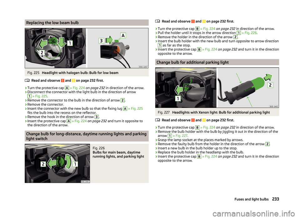
Replacing the low beam bulbFig. 225
Headlight with halogen bulb: Bulb for low beam
Read and observe
and on page 232 first.
›
Turn the protective cap
A
» Fig. 224 on page 232 in direction of the arrow.
›
Disconnect the connector with the light bulb in the direction of arrow
1
» Fig. 225 .
›
Remove the connector to the bulb in the direction of arrow
2
.
›
Remove the connector.
›
Insert the connector with the new bulb so that the fixing lug
A
» Fig. 225
fits the bulb into the recess on the reflector.
›
Remove the hook in the direction of arrow
3
.
›
Insert the protective cap
A
» Fig. 224 on page 232 and turn it opposite to
the direction of the arrow.
Change bulb for long-distance, daytime running lights and parking
light switch
Fig. 226
Bulbs for main beam, daytime
running lights, and parking light
Read and observe and on page 232 first.›
Turn the protective cap
B
» Fig. 224 on page 232 in direction of the arrow.
›
Pull the holder until it stops in the arrow direction
1
» Fig. 226 .
›
Remove the holder in the direction of the arrow
2
.
›
Insert the bulb holder with the new bulb and turn opposite to arrow direction
1
as far as the stop.
›
Insert the protective cap
B
» Fig. 224 on page 232 and turn it in the direction
opposite to the arrow.
Change bulb for additional parking light
Fig. 227
Headlights with Xenon light: Bulb for additional parking light
Read and observe
and on page 232 first.
›
Turn the protective cap
B
» Fig. 224 on page 232 in direction of the arrow.
›
Remove the bulb holder with the bulb by jiggling it out in the direction of the
arrow
1
» Fig. 227 .
›
Grasp the lamp socket at the places marked by arrows.
›
Remove the faulty bulb from the holder in the direction of the arrow
2
.
›
Insert a new bulb in the bulb holder up to the stop.
›
Replace the bulb holder in the headlamp with the bulb.
›
Insert the protective cap
B
» Fig. 224 on page 232 and turn it in the direction
opposite to the arrow.
233Fuses and light bulbs